This article includes everything you need to know about controlling a stepper motor with the A4988 stepper motor driver and Arduino. I have included a wiring diagram, a tutorial on how to set the current limit and many example codes.
Although you can use this driver without an Arduino library, I highly recommend you also take a look at the example code for the AccelStepper library at the end of this tutorial. This library is fairly easy to use and can greatly improve the performance of your hardware.
After each example, I break down and explain how the code works, so you should have no problems modifying it to suit your needs.
If you would like to learn more about other stepper motor drivers, then the articles below might be useful:
- How to control a stepper motor with DRV8825 driver and Arduino
- 28BYJ-48 Stepper Motor with ULN2003 Driver and Arduino Tutorial
- How to control a Stepper Motor with Arduino Motor Shield Rev3
- TB6600 Stepper Motor Driver with Arduino Tutorial
I also have an article on How To Drive a Stepper Motor using the A4988 driver and ESP32 if you want to work with an ESP32 microcontroller instead.
Required Parts
Hardware components
| A4988 stepper motor driver | × 1 | Amazon | |
| NEMA 17 stepper motor | × 1 | Amazon | |
| Arduino Uno Rev3 | × 1 | Amazon | |
| Power supply (8-35 V) | × 1 | Amazon | |
| Breadboard | × 1 | Amazon | |
| Capacitor (100 µF) | × 1 | Amazon | |
| Jumper wires | ~ 10 | Amazon | |
| USB cable type A/B | × 1 | Amazon |
I like to use this driver in combination with a CNC-shield or expansion board. Such a shield already includes capacitors and offers an easy way to select the microstepping resolution. It makes wiring much easier and is a great option if you need a more permanent solution than a breadboard.
Tools
Software
Makerguides.com is a participant in the Amazon Services LLC Associates Program, an affiliate advertising program designed to provide a means for sites to earn advertising fees by advertising and linking to products on Amazon.com. As an Amazon Associate we earn from qualifying purchases.
About the driver
At the heart of the A4988 driver you will find a chip made by Allegro MicroSystems: the A4988 DMOS Microstepping Driver with Translator and Overcurrent Protection. This integrated motor driver makes interfacing with a microcontroller super easy as you only need two pins to control both the speed and the direction of the stepper motor.
The driver has a maximum output capacity of 35 V and ± 2 A which is great for driving small to medium-sized stepper motors like a NEMA 17 bipolar stepper motor.
If you need to control larger stepper motors like NEMA 23, take a look at the TB6600 stepper motor driver. This driver can be used with the same code as the A4988 and has a current rating of 3.5 A.
The A4988 driver chip has several safety functions built-in like overcurrent, short circuit, under-voltage lockout, and over-temperature protection. You can find more specifications in the table below.
A4988 Specifications
| Minimum operating voltage | 8 V |
| Maximum operating voltage | 35 V |
| Continuous current per phase | 1 A |
| Maximum current per phase | 2 A |
| Minimum logic voltage | 3 V |
| Maximum logic voltage | 5.5 V |
| Microstep resolution | full, 1/2, 1/4, 1/8 and 1/16 |
| Reverse voltage protection? | No |
| Dimensions | 15.5 × 20.5 mm (0.6″ × 0.8″) |
| Cost | Check price |
For more information you can check out the datasheet here.
Differences between the A4988 and DRV8825
The DRV8825 is quite similar to the A4988 but there are some key differences:
- The DRV8825 offers 1/32 microstepping, whereas the A4988 only goes down to 1/16-step. Higher microstepping results in smoother, quieter operation but is not always needed.
- The current limit potentiometer is at a different location
- The relation between the reference voltage and the current limit is different.
- The DRV8825 requires a minimum STEP pulse duration of 1.9µs; the A4988 requires 1µs minimum.
- The DRV8825 can be used with a higher voltage motor power supply (45 V vs 35 V). This means it is less susceptible to damage from LC voltage spikes.
- The DRV8825 can deliver slightly more current than the A4988 without any additional cooling.
Note that the pinout of the DRV8825 is exactly the same as for the A4988, so it can be used as a drop-in replacement!
Microstep settings
Stepper motors typically have a step size of 1.8° or 200 steps per revolution, this refers to full steps. A microstepping driver such as the A4988 allows higher resolutions by allowing intermediate step locations. This is achieved by energizing the coils with intermediate current levels.
For instance, driving a motor in quarter-step mode will give the 200-step-per-revolution motor 800 microsteps per revolution by using four different current levels.
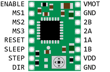
The resolution (step size) selector pins (MS1, MS2, and MS3) allow you to select one of the five step resolutions according to the table below.
| MS1 | MS2 | MS3 | Microstep resolution |
|---|---|---|---|
| Low | Low | Low | Full step |
| High | Low | Low | 1/2 step |
| Low | High | Low | 1/4 step |
| High | High | Low | 1/8 step |
| High | High | High | 1/16 step |
All three inputs have internal 100 kΩ pull-down resistors, so leaving the three microstep selection pins disconnected results in full-step mode.
I often use a CNC-shield or expansion board in combination with these drivers. The expansion board has 3 dip switches to set MS1 – MS3 high or low and on the CNC-shield you can install jumpers. If you are using the driver with a breadboard, you can just use jumper wires to connect the selector pins to 5 V (i.e. make them HIGH).
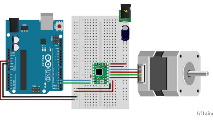
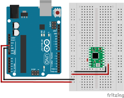
Wiring – Connecting A4988 to Arduino and stepper motor
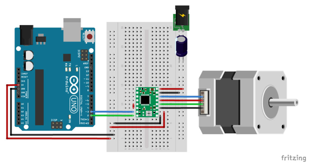
The wiring diagram/schematic above shows you how to connect the A4899 driver to a stepper motor and the Arduino. The connections are also given in the following table:
A4988 Connections
| A4988 | Connection |
|---|---|
| VMOT | 8-35V |
| GND | Motor ground |
| SLP | RESET |
| RST | SLP |
| VDD | 5V |
| GND | Logic ground |
| STP | Pin 3 |
| DIR | Pin 2 |
| 1A, 1B, 2A, 2B | Stepper motor |
- The motor power supply is connected to GND and VMOT (top right).
- The two coils of the stepper motor are connected to 1A, 1B and 2A, 2B (see below).
- The GND pin (lower right) is connected to the ground pin of the microcontroller and VDD is connected to 5V.
- The STP (step) and DIR (direction) pin are connected to digital pin 3 and 2 respectively. You can choose a different digital pin if you want, but these are the ones I used for this tutorial and the example code.
- The SLP pin is an active low input. Meaning, pulling this pin low puts the driver in sleep mode, minimizing the power consumption. RST is also an active low input. When pulled low, all STEP inputs are ignored until you pull it high. If you are not using the pin, you can connect it to the adjacent SLP/SLEEP pin to bring it high and enable the driver.
- The EN (enable) pin can be left disconnected, it is pulled low by default. When this pin is set high the driver is disabled.
In the rest of this tutorial I have left MS1, MS2 and MS3 disconnected, so the driver operates in full-step mode. This makes explaining the code a bit easier. Normally I would use 1/8 or 1/16 microstepping and connect the appropriate pins to 5V (see the table in the introduction).
Warning
The A4988 carrier board uses low-ESR ceramic capacitors, which makes it susceptible to destructive LC voltage spikes, especially when using power leads longer than a few inches.
To protect the driver you can connect an electrolytic capacitor between VMOT and GND. Pololu suggests a capacitor of 47 µF or more (I used a 100 µF capacitor). I like these assortment boxes from Amazon, this way I always have some capacitors of the right size on hand.
How to determine the correct stepper motor wiring?
If you can’t find the datasheet of your stepper motor, it can be difficult to figure out how to wire your motor correctly. I use the following trick to determine how to connect 4 wire bipolar stepper motors:
The only thing you need to identify is the two pairs of wires which are connected to the two coils of the motor. The wires from one coil get connected to 1A and 1B and the other to 2A and 2B, the polarity doesn’t matter.
To find the two wires from one coil, do the following with the motor disconnected:
- Try to spin the shaft of the stepper motor by hand and notice how hard it is to turn.
- Now pick a random pair of wires from the motor and touch the bare ends together.
- Next, try to spin the shaft of the stepper motor again.
If you feel a lot of resistance, you have found a pair of wires from the same coil. If you can spin the shaft freely, try another pair of wires. Now connect the two coils to the pins shown in the wiring diagram above.
How to set the current limit?
Before you start programming your Arduino and start using the driver there is one very important thing you need to do that a lot of people forget: set the current limit!
This step is not very complicated but absolutely necessary to protect your stepper motor and the driver. If you do not set an appropriate current limit, your motor can draw more current than it or your driver can handle, this is likely to damage one or both of them.
To set the current limit you need to measure a reference voltage and adjust the on-board potentiometer accordingly. You will need a small screwdriver, a multimeter to measure the reference voltage, and alligator test leads (optional but very handy).
To measure the reference voltage, the driver needs to be powered. The A4988 only needs power via VDD (5V) and you need to connect RST and SLP together, otherwise the driver won’t turn on. It’s best to disconnect the stepper motor while you do this.
If you have already wired up the driver, you can leave everything but the stepper motor connected. You can apply power through the USB port of the Arduino.
| A4988 | Connection |
|---|---|
| VDD | 5V |
| RST | SLP |
| SLP | RESET |
| GND | Ground |
Current limit formula
The next step is to calculate the current limit with the following formula:
Current Limit = Vref ÷ (8 × Rcs)
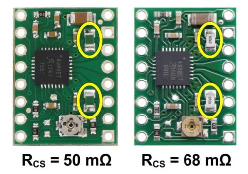
The Rcs is the current sense resistance. If you bought a A4988 driver from Pololu before January 2017, the Rcs will be 0.050 Ω. Drivers sold after that have 0.068 Ω current sense resistors.
So this means that for a current limit of 1A for a board with 0.068 Ω current sense resistors, the Vref should be 540 mV.
To select the right current limit, take a look at the datasheet of your stepper motor. If you can’t find the current rating of your motor, I recommend starting with a current limit of 1A. You can always increase it later if your motor/driver is missing steps.
When using the driver in full-step mode, the current through each coil is limited to approximately 70% of the set current limit. This means that you would need to set the current limit 40% higher or 1.4 A in full-step mode. When using microstepping, the formula above applies.
Note that you need to re-calibrate the current limit if you change the motor power supply voltage. If your motor is making a lot of noise, try to lower the current limit. It’s best to set the current limit just high enough so the motor doesn’t miss steps.
Measuring Vref
Now you will need to measure the reference voltage (Vref) between the two points marked on the picture below (GND and the potentiometer) and adjust it to the value you calculated.
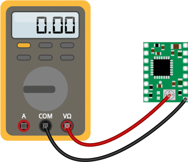
I recommend using alligator test leads clamped to the screwdriver to set the current limit. This allows you to adjust the potentiometer and measure the reference voltage at the same time.
Note: There is another way to measure the current limit and that is to directly measure the current draw of the stepper motor. Personally I find the above method a lot easier.
Pololu mentions the following on their website:
Note: The coil current can be very different from the power supply current, so you should not use the current measured at the power supply to set the current limit. The appropriate place to put your current meter is in series with one of your stepper motor coils.
Current limit FAQ
Do I need to have the stepper motor connected or not?
No, you don’t need to connect the stepper motor to the driver when setting the current limit. To be on the safe side, disconnect your motor, it sometimes interferes with measuring the Vref voltage.
Do I need to turn the motor by running the Arduino motor sketch?
No, see question above.
Do I need to turn the potentiometer clock- or counter- clockwise to raise Vref?
This depends on the manufacturer of the driver. If you have a genuine Polulu breakout board of the DRV8825 or A4988 you turn the potentiometer clockwise to raise Vref and counter- clockwise to lower it.
Cooling the driver
The A4988 driver IC has a maximum current rating of 2 A per coil, but without a heat sink it can only supply about 1 A per coil before it starts to overheat.
The driver usually comes with a small adhesive-backed heat sink, which I recommend you to install right away. You can also buy a bunch of small heat sinks from Amazon for really cheap.
Basic Arduino example code to control a stepper motor
Now that you have wired up the driver and set the current limit, it is time to connect the Arduino to the computer and upload some code. You can upload the following example code to your Arduino using the Arduino IDE. For this specific example, you do not need to install any libraries.
This sketch controls both the speed, the number of revolutions, and the spinning direction of the stepper motor.
// Example sketch to control a stepper motor with A4988 stepper motor driver
// and Arduino without a library.
// More info: https://www.makerguides.com

// Define stepper motor connections and steps per revolution:
#define dirPin 2
#define stepPin 3
#define stepsPerRevolution 200

void setup() {
  // Declare pins as output:
  pinMode(stepPin, OUTPUT);
  pinMode(dirPin, OUTPUT);
}

void loop() {
  // Set the spinning direction clockwise:
  digitalWrite(dirPin, HIGH);

  // Spin the stepper motor 1 revolution slowly:
  for (int i = 0; i < stepsPerRevolution; i++) {
    // These four lines result in 1 step:
    digitalWrite(stepPin, HIGH);
    delayMicroseconds(2000);
    digitalWrite(stepPin, LOW);
    delayMicroseconds(2000);
  }

  delay(1000);

  // Set the spinning direction counterclockwise:
  digitalWrite(dirPin, LOW);

  // Spin the stepper motor 1 revolution quickly:
  for (int i = 0; i < stepsPerRevolution; i++) {
    // These four lines result in 1 step:
    digitalWrite(stepPin, HIGH);
    delayMicroseconds(1000);
    digitalWrite(stepPin, LOW);
    delayMicroseconds(1000);
  }

  delay(1000);

  // Set the spinning direction clockwise:
  digitalWrite(dirPin, HIGH);

  // Spin the stepper motor 5 revolutions fast:
  for (int i = 0; i < 5 * stepsPerRevolution; i++) {
    // These four lines result in 1 step:
    digitalWrite(stepPin, HIGH);
    delayMicroseconds(500);
    digitalWrite(stepPin, LOW);
    delayMicroseconds(500);
  }

  delay(1000);

  // Set the spinning direction counterclockwise:
  digitalWrite(dirPin, LOW);

  //Spin the stepper motor 5 revolutions fast:
  for (int i = 0; i < 5 * stepsPerRevolution; i++) {
    // These four lines result in 1 step:
    digitalWrite(stepPin, HIGH);
    delayMicroseconds(500);
    digitalWrite(stepPin, LOW);
    delayMicroseconds(500);
  }

  delay(1000);
}
How the code works:
The sketch starts with defining the step and direction pins. I connected them to Arduino pin 3 and 2.
The statement #define is used to give a name to a constant value. The compiler will replace any references to this constant with the defined value when the program is compiled. So everywhere you mention dirPin, the compiler will replace it with the value 2 when the program is compiled.
I also defined a stepsPerRevolution constant. Because I set the driver to full step mode I set it to 200 steps per revolution. Change this value if your setup is different.
// Define stepper motor connections and steps per revolution
#define dirPin 2
#define stepPin 3
#define stepsPerRevolution 200
In the setup() section of the code, all the motor control pins are declared as digital OUTPUT with the function pinMode().
void setup() {
  // Declare pins as output:
  pinMode(stepPin, OUTPUT);
  pinMode(dirPin, OUTPUT);
}
In the loop() section of the code, we let the motor spin one revolution slowly in the CW direction and one revolution quickly in the CCW direction. Next, we let the motor spin 5 revolutions in each direction with a high speed. So how do you control the speed, spinning direction, and number of revolutions?
  // Set the spinning direction clockwise:
  digitalWrite(dirPin, HIGH);

  // Spin the stepper motor 1 revolution slowly:
  for(int i = 0; i < stepsPerRevolution; i++)
  {
    // These four lines result in 1 step:
    digitalWrite(stepPin, HIGH);
    delayMicroseconds(2000);
    digitalWrite(stepPin, LOW);
    delayMicroseconds(2000);
  }
Control spinning direction:
To control the spinning direction of the stepper motor we set the DIR (direction) pin either HIGH or LOW. For this we use the function digitalWrite(). Depending on how you connected the stepper motor, setting the DIR pin high will let the motor turn CW or CCW.
Control number of steps or revolutions:
In this example sketch, the for loops control the number of steps the stepper motor will take. The code within the for loop results in 1 step of the stepper motor. Because the code in the loop is executed 200 times (stepsPerRevolution), this results in 1 revolution. In the last two loops, the code within the for loop is executed 1000 times, which results in 1000 steps or 5 revolutions.
Note that you can change the second term in the for loop to whatever number of steps you want. for(int i = 0; i < 100; i++) would result in 100 steps, or half a revolution.
Control speed:
The speed of the stepper motor is determined by the frequency of the pulses we send to the STEP pin. The higher the frequency, the faster the motor runs. You can control the frequency of the pulses by changing delayMicroseconds() in the code. The shorter the delay, the higher the frequency, the faster the motor runs.
AccelStepper library tutorial
The AccelStepper library written by Mike McCauley is an awesome library to use for your project. One of the advantages is that it supports acceleration and deceleration, but it has a lot of other nice functions too.
You can download the latest version of this library here or click the button below.
You can install the library by going to Sketch > Include Library > Add .ZIP Library… in the Arduino IDE.
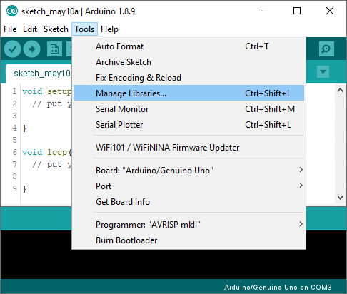
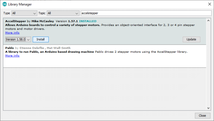
Another option is to navigate to Tools > Manage Libraries… or type Ctrl + Shift + I on Windows. The Library Manager will open and update the list of installed libraries.
You can search for ‘accelstepper’ and look for the library by Mike McCauley. Select the latest version and then click Install.
1. Continuous rotation example code
The following sketch can be used to run one or more stepper motors continuously at a constant speed. (No acceleration or deceleration is used).
/*
  Example sketch to control a stepper motor with A4988 stepper motor driver,
  AccelStepper library and Arduino: continuous rotation.
  More info: https://www.makerguides.com
*/

// Include the AccelStepper library:
#include "AccelStepper.h"

// Define stepper motor connections and motor interface type.
// Motor interface type must be set to 1 when using a driver
#define dirPin 2
#define stepPin 3
#define motorInterfaceType 1

// Create a new instance of the AccelStepper class:
AccelStepper stepper = AccelStepper(motorInterfaceType, stepPin, dirPin);

void setup() {
  // Set the maximum speed in steps per second:
  stepper.setMaxSpeed(1000);
}

void loop() {
  // Set the speed in steps per second:
  stepper.setSpeed(400);
  // Step the motor with a constant speed as set by setSpeed():
  stepper.runSpeed();
}
How the code works:
The first step is to include the library with #include "AccelStepper.h".
// Include the AccelStepper library:
#include "AccelStepper.h"
The next step is to define the A4988 to Arduino connections and the motor interface type. The motor interface type must be set to 1 when using a step and direction driver. You can find the other interface types here.
The statement #define is used to give a name to a constant value. The compiler will replace any references to this constant with the defined value when the program is compiled. So everywhere you mention dirPin, the compiler will replace it with the value 2 when the program is compiled.
// Define stepper motor connections and motor interface type.
// Motor interface type must be set to 1 when using a driver
#define dirPin 2
#define stepPin 3
#define motorInterfaceType 1
Next, you need to create a new instance of the AccelStepper class with the appropriate motor interface type and connections.
In this case, I called the stepper motor ‘stepper’ but you can use other names as well, like ‘z_motor’ or ‘liftmotor’ etc. AccelStepper liftmotor = AccelStepper(motorInterfaceType, stepPin, dirPin);. The name that you give to the stepper motor will be used later to set the speed, position, and acceleration for that particular motor. You can create multiple instances of the AccelStepper class with different names and pins. This allows you to easily control 2 or more stepper motors at the same time.
// Create a new instance of the AccelStepper class:
AccelStepper stepper = AccelStepper(motorInterfaceType, stepPin, dirPin);
In the setup() section of the code we define the maximum speed in steps/second. Speeds of more than 1000 steps per second can be unreliable, so I set this as the maximum. Note that I specify the name of the stepper motor (‘stepper’), for which I want to define the maximum speed. If you have multiple stepper motors connected, you can specify a different speed for each motor:
void setup() {
  // Set the maximum speed in steps per second:
  stepper.setMaxSpeed(1000);
  stepper2.setMaxSpeed(500);
}
In the loop() we first set the speed that we want the motor to run at. For this, we use the function setSpeed(). (you can also place this in the setup section of the code).
stepper.runSpeed() polls the motor and when a step is due, executes 1 step. This depends on the set speed and the time since the last step. If you want to change the direction of the motor, you can set a negative speed: stepper.setSpeed(-400); turns the motor the other way.
void loop() {
  // Set the speed in steps per second:
  stepper.setSpeed(400);
  // Step the motor with a constant speed as set by setSpeed():
  stepper.runSpeed();
}
2. Example code to control number of steps or revolutions
To let the motor rotate a specific number of steps I prefer to use a while loop in combination with stepper.currentPosition(). You can use the following example code, to let the motor run back and forth.
/*
  Example sketch to control a stepper motor with A4988 stepper motor driver,
  AccelStepper library and Arduino: number of steps or revolutions.
  More info: https://www.makerguides.com
*/

// Include the AccelStepper library:
#include "AccelStepper.h"

// Define stepper motor connections and motor interface type.
// Motor interface type must be set to 1 when using a driver
#define dirPin 2
#define stepPin 3
#define motorInterfaceType 1

// Create a new instance of the AccelStepper class:
AccelStepper stepper = AccelStepper(motorInterfaceType, stepPin, dirPin);

void setup() {
  // Set the maximum speed in steps per second:
  stepper.setMaxSpeed(1000);
}

void loop() {
  // Set the current position to 0:
  stepper.setCurrentPosition(0);

  // Run the motor forward at 200 steps/second until the motor reaches 400 steps (2 revolutions):
  while(stepper.currentPosition() != 400)
  {
    stepper.setSpeed(200);
    stepper.runSpeed();
  }

  delay(1000);

  // Reset the position to 0:
  stepper.setCurrentPosition(0);

  // Run the motor backwards at 600 steps/second until the motor reaches -200 steps (1 revolution):
  while(stepper.currentPosition() != -200)
  {
    stepper.setSpeed(-600);
    stepper.runSpeed();
  }

  delay(1000);

  // Reset the position to 0:
  stepper.setCurrentPosition(0);

  // Run the motor forward at 400 steps/second until the motor reaches 600 steps (3 revolutions):
  while(stepper.currentPosition() != 600)
  {
    stepper.setSpeed(400);
    stepper.runSpeed();
  }

  delay(3000);
}
Code explanation:
The first part of the code up to the loop() section is exactly the same as in the previous example.
In the loop I make use of a while loop in combination with the currentPosition() function. First, I set the current position of the stepper motor to zero with stepper.setCurrentPosition(0).
  // Set the current position to 0:
  stepper.setCurrentPosition(0);
Next we make use of the while loop. A while loop will loop continuously, and infinitely, until the expression inside the parenthesis, () becomes false. So, in this case, I check if the current position of the stepper motor is not equal to 400 steps (!= means: is not equal to). While this is not the case, we run the stepper motor at a constant speed as set by setSpeed().
  // Run the motor forward at 200 steps/second until the motor reaches 400 steps (2 revolutions):
  while(stepper.currentPosition() != 400)
  {
    stepper.setSpeed(200);
    stepper.runSpeed();
  }
In the rest of the loop, we do exactly the same, just with a different speed and target position.
3. Acceleration and deceleration example code
With the following sketch, you can add acceleration and deceleration to the movements of the stepper motor, without any complicated coding. In the following example, the motor will run back and forth with a speed of 200 steps per second and an acceleration of 30 steps per second per second.
/*
  Example sketch to control a stepper motor with A4988 stepper motor driver,
   AccelStepper library and Arduino: acceleration and deceleration.
   More info: https://www.makerguides.com
*/

// Include the AccelStepper library:
#include "AccelStepper.h"

// Define stepper motor connections and motor interface type.
// Motor interface type must be set to 1 when using a driver
#define dirPin 2
#define stepPin 3
#define motorInterfaceType 1

// Create a new instance of the AccelStepper class:
AccelStepper stepper = AccelStepper(motorInterfaceType, stepPin, dirPin);

void setup() {
  // Set the maximum speed and acceleration:
  stepper.setMaxSpeed(200);
  stepper.setAcceleration(30);
}

void loop() {
  // Set the target position:
  stepper.moveTo(600);
  // Run to target position with set speed and acceleration/deceleration:
  stepper.runToPosition();

  delay(1000);

  // Move back to zero:
  stepper.moveTo(0);
  stepper.runToPosition();

  delay(1000);
}
Code explanation:
In the setup(), besides the maximum speed, we need to define the acceleration/deceleration. For this we use the function setAcceleration().
void setup() {
  // Set the maximum speed and acceleration:
  stepper.setMaxSpeed(200);
  stepper.setAcceleration(30);
}
In the loop section of the code, I used a different way to let the motor rotate a predefined number of steps. The function stepper.moveTo() is used to set the target position. The function stepper.runToPostion() moves the motor (with acceleration/deceleration) to the target position and blocks until it is at the target position. Because this function is blocking, you shouldn’t use this when you need to control other things at the same time.
  // Set the target position:
  stepper.moveTo(600);
  // Run to target position with set speed and acceleration/deceleration:
  stepper.runToPosition();
Conclusion
In this article I have shown you how to control a stepper motor with the A4988 stepper motor driver and Arduino. I hope you found it useful and informative. If you did, please share it with a friend who also likes electronics and making things!
I have personally used this driver a lot for a bunch of 3D printers and other CNC related projects. But I would love to know what projects you plan on building (or have already built) with this driver. If you have any questions or if you think that things are missing, please leave a comment down below.
Benne is professional Systems Engineer with a deep expertise in Arduino and a passion for DIY projects.
lavanant
Thursday 19th of October 2023
je finalise un projet utisant 2 moteurs. mon materiel: arduino uno +CNC shield v3+tb6600 moteur nema 17HS13-0404S-PG27 avec a4988 moteur nema 23 avec tb6600 bouton poussoir pour demarer le programme batterie 18V mon probleme= quand jutilise gbrl les moteurs fonctionnent paefaitement,par contre quand j'utilise mon programme (avec accelstepper) le nema 17 n'a pas de couple et fait du bruit en hesitant pour passer d'une phase a l'autre. y a t il une explication a cela
John
Monday 7th of August 2023
Super tuto, Mon projet sera un robot auto équilibré sur 2 roues
marlon
Thursday 20th of October 2022
hello sir great tutorial, can you help me to program two nema 17, a lcd and 5 buttons? thank you
Dan Wilbanks
Tuesday 4th of October 2022
Three questions; 1. Is the motor shield used in conjunction with the DRV8825? 2. What motor shield from Pololu would you suggest? (NEMA 17) 3. Will an Arduino Uno from 2019 be to old? I don't know the revision #. Thanks.
James
Thursday 22nd of September 2022
I need to build a balancing 2 wheeled robot on an STM32 Nucleo board for a Uni Project. This is helpful, thanks!