In this blog post, you will learn how to use the ACS712 current sensor with an Arduino to measure DC and AC currents. By the end of this tutorial, you will have a clear understanding of how the ACS712 sensor works, how to connect it to an Arduino, and how to read and display current data using code examples.
Let’s get started.
Required Parts
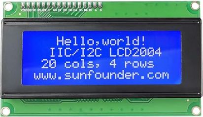
Below you will find the parts required for this project. Instead of the larger 20×4 LCD display you could also use a smaller 16×2 LCD display. Just make sure it has an I2C interface and not the also common SPI interface.
Also there are three different types of ACS712 Current Sensors for different current ranges (5A, 20A, 30A). The provided link is for a set of those three plus an additional Voltage Sensor Module. If you know the current range of your application, you can also buy the suitable modules individually.

Arduino Uno

Dupont Wire Set

Breadboard

USB Cable for Arduino UNO
LCD Display
ACS712 Current Sensor
Makerguides.com is a participant in the Amazon Services LLC Associates Program, an affiliate advertising program designed to provide a means for sites to earn advertising fees by advertising and linking to products on Amazon.com. As an Amazon Associate we earn from qualifying purchases.
How ACS712 Current Sensor Works
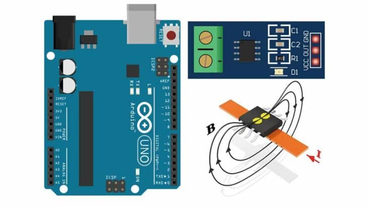
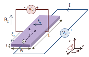
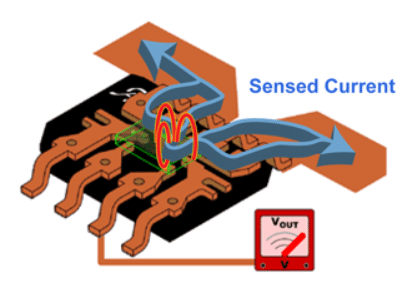
The ACS712 current sensor is based on the Hall Effect principle, where a magnetic field perpendicular to the current flow generates a voltage proportional to the current passing through the sensor.
This voltage can then be converted into a current measurement by reading the voltage with an Arduino analog input and scaling it.
The ACS712 sensor is a small IC with a built in Hall Effect sensor. It detects the magnetic field generated by the current passing through the sensor’s conductor and outputs a voltage proportional to the current passing through the sensor (see picture below).
Note that the ACS712 sensor can be used for DC and AC currents, and also measures negative and positive DC currents.
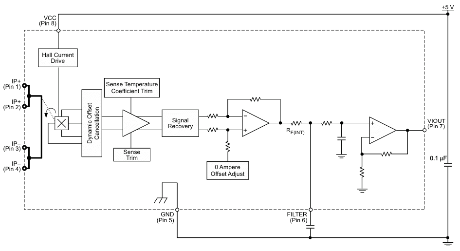
Internal Circuitry
Inside the ACS712 IC, there is the Hall Effect sensor, a differential amplifier, and a precision voltage regulator. The differential amplifier amplifies the voltage generated by the Hall Effect sensor to provide an accurate current measurement. While the precision voltage regulator ensures stable operation and accurate readings.
Specification
The main features of the ACS712 are listed below. For more details see the Datasheet of the ACS712. In summary the sensor runs on 5V (or other voltages), is very fast, covers a large current range and is easy to use.
- 5 µs output rise time in response to step input current
- 80 kHz bandwidth
- Total output error 1.5% at TA = 25°C
- 1.2 mΩ internal conductor resistance
- 2.1 kVRMS minimum isolation voltage
- 5.0 V, single supply operation
- 66 to 185 mV/A output sensitivity
- Output voltage proportional to AC or DC currents
- Factory-trimmed for accuracy
Different Versions of ACS712 Current Sensor
Note that there are three different versions of ACS712 Current Sensor for different current ranges such as 5A, 20A and 30A. Superficially, the ACS712 Modules for the different currents look identical. See the picture below.
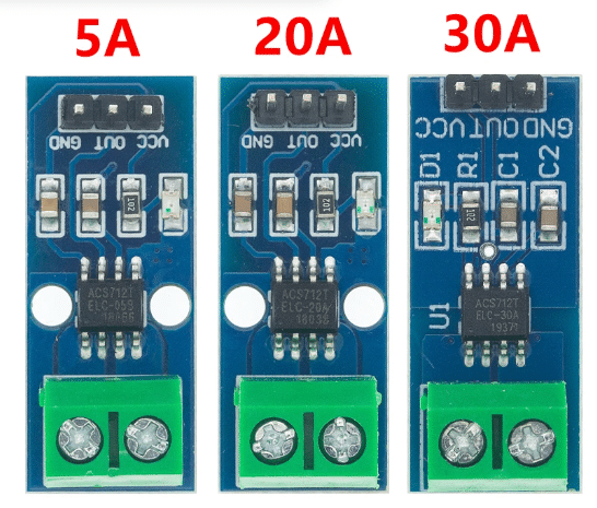
But if you look closely, you can see that the ACS712 ICs on the boards are labelled as ELC-05B, ELC-20A and ELC-30A for the 5A, 20A and 30A versions, respectively. Apart from the different current ranges, the modules have also different sensitivities and typical applications.
ACS712-05B
- Measures up to ±5A current range.
- Sensitivity of 185mV/A.
- Ideal for low-current applications.
- Suitable for small-scale projects and low-power devices.
ACS712-20A
- Measures up to ±20A current range.
- Sensitivity of 100mV/A.
- Suitable for medium-current applications.
- Commonly used in home automation systems and robotics projects.
ACS712-30A
- Measures up to ±30A current range.
- Sensitivity of 66mV/A.
- Best for high-current applications.
- Ideal for industrial automation and power monitoring applications.
Note that the larger the current range the lower is the sensor resolution. This means for maximum accuracy you want to pick the module that matches the max current of your application.
Pinout of ACS712 Current Sensor Module
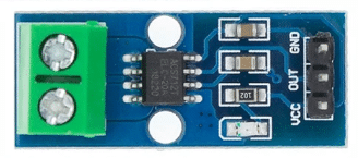
Typically, you don’t connect the ACS712 IC directly to an Arduino but instead use a ACS712 Sensor Breakout Module that has the ACS712 IC, some additional resistors and a power LED. They are much easier to connect. The picture below shows the pinout of a typical ACS712 Sensor Module.
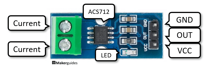
On the terminal side (green) you connect the current you want to measure. And on the other side is the power supply (VCC, GND) for the sensor, and the sensor output pin (OUT).
Measuring Circuit
To measure a current you have to insert the ACS712 into a circuit that at minimum has a Power source (DC or AC) and a Load, for instance a resistor, motor or lamp. See the example below.
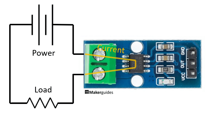
Note that you will not have much success, if you use a 9V battery as power source and a LED with resistor as load. The typical current of such a circuit would be at around 0.020A. Since the smallest current range of the ACS712 is 5 Ampere, you will not get much of a signal on the sensor output.
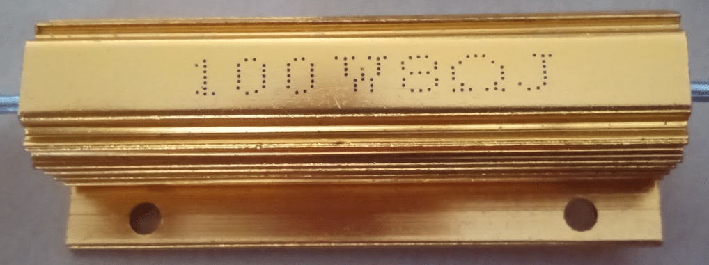
Instead pick a power supply that can deliver a few Ampere and a Load that can consume a few Ampere as well. A regulated power supply with a current limiter and a high wattage, low ohm resistor (e.g. 8 Ohm, 100W) are better suited to try out the ACS712.
If you want to verify that the current readings of the ACS712 are accurate, you can add a Multimeter to the circuit as follows:
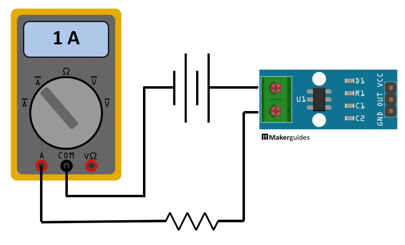
Just make sure that you connect your Multimeter for current readings and select the correct range for current measurements.
Connecting ACS712 with Arduino
Connecting the ACS712 Module to an Arduino is very simple. We just need to connect VCC of the Module to the 5V pin of the Arduino (red wire), and GND of the Module to the GND pin of the Arduino (black wire). Finally, we need to connect the Sensor output (OUT) to the analog input A0 of the Arduino (white wire).
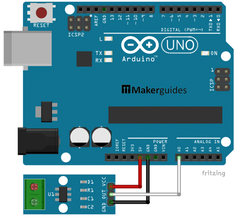
And that’s it. If you connect your Arduino to power the red power LED off the ACS712 Module should come on. In the next section, I show you the code to read data from the ACS712.
Code for Reading ACS712 Current Data
Below you will find the code for measuring currents with the ACS712. Have a quick look at the complete code first, before we dive into its details.
// Measure current with ACS712
// and print on Serial Monitor
const int nSamples = 1000;
const float vcc = 5.0;
const int adcMax = 1023;

const float sens = 0.185;  // 5A
//const float sens = 0.100;  // 20A
//const float sens = 0.66;  // 30A

float avg() {
  float val = 0;
  for (int i = 0; i < nSamples; i++) {
    val += analogRead(A0);
    delay(1);
  }
  return val / adcMax / nSamples;
}

void setup() {
  Serial.begin(9600);
}

void loop() {
  float cur = (vcc / 2 - vcc * avg()) / sens;
  Serial.print("Current:");
  Serial.println(cur);
}
The main function of the code is to read 1000 times (with a delay of 1 msec) the voltage from the analog input A0, average this value and then converting it into a current.
Constants and Variables
We start by defining several constants such as nSamples for the number of samples for the average, vcc for the power supply voltage, and sens for the sensitivity of the ACS712 sensor. Depending on which of the sensors you use (5A, 20A, 30A), comment in the relevant line in the code.
We use a voltage VCC of 5V but the ACS712 can run on lower or higher voltages as well (e.g 3.3V when using an ESP32). If you do that, you would need to adjust the vcc constant accordingly.
Finally, we have the maximum value adcMax the Analog Digital Converter (ADC) of an Arduino Uno can return. If you use a different Arduino or an ESP32 check the resolution of its ADC and set adcMax accordingly. For instance, ESP32 boards usually have an ADC with a resolution of 4096 steps, meaning adcMax = 4095.
const int nSamples = 1000;
const byte lcdAdr = 0x3F;
const float vcc = 5.0;
const int adcMax = 1023;

const float sens = 0.185;  // 5A
//const float sens = 0.100;  // 20A
//const float sens = 0.66;  // 30A
Averaging Function
The avg() function calculates the average analog reading from pin A0 over the specified number of nSamples. It iterates through the samples, reads the analog value, and delays for 1ms before calculating and returning the average value.
This means it will take 1 sec for a complete reading. We use averaging here, to smoothen out fluctuations in the sensor readings. You can use less samples, let’s say 100 to get faster readings, but they will be less stable.
Note that we divide val by adcMax, which transforms the sensor values to a range from 0 to 1.
float avg() {
  float val = 0;
  for (int i = 0; i < nSamples; i++) {
    val += analogRead(A0);
    delay(1);
  }
  return val / 1024 / nSamples ;
}
Setup Function
In the setup() function, the serial communication is initialized at a baud rate of 9600. This allows us to send the current measurement data to the serial monitor for debugging and analysis.
void setup() {
  Serial.begin(9600);
}
Loop Function
The loop() function calculates the current based on the formula using the voltage, average analog reading, and sensor sensitivity. It then prints the calculated current value to the serial monitor for observation.
void loop() {
  float cur = (vcc / 2 - vcc * avg()) / sens;
  Serial.print("Current:");
  Serial.println(cur);
}
If the ACS712 is not connected to any current, it returns a a voltage (OUT) that is half of its supply volage (VCC). Sensor values below that midpoint indicate a negative current and above a positive current.
cur = (vcc / 2 – vcc * avg()) / sens
We therefore multiply VCC with our average avg and subtract it from the midpoint vcc/2 to get a value proportional to the current through the sensor. Depending on the type of the ACS712 (5A, 20A, 30A), we then have to divide this value be the sensors sensitivity sens, to get the current reading cur in Ampere units.
And there you have it! Now you can measure fairly high currents with your Arduino. In the next section we add an LCD to show the current readings on a display, instead of relying on the Serial Monitor.
Adding an LCD to Display Currents
Adding the LCD to the circuit is easy. First connect 5V and GND of the Arduino to VCC and GND of the LCD. Then we need to connect A4 of the Arduino to the SDA pin of the LCD, and A5 to the SCL pin. Keep the connections of the ACS712 Module as they are.
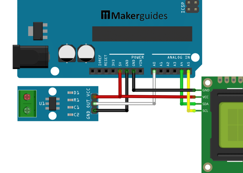
And that’s it. Note that you may have to adjust the brightness of the LCD, if you don’t see any outputs, when running the code of the next section.
Code to Display Current Readings on the LCD
The code to display the current readings of the ACS712 on the LCD is a simple extension of the code we used above. Have a quick look and then we discuss the details.
// Measure current with ACS712
// and print on LCD
#include "LiquidCrystal_I2C.h"

const int nSamples = 1000;
const float vcc = 5.0;
const int adcMax = 1023;
const byte lcdAdr = 0x3F;


const float sens = 0.185;  // 5A
//const float sens = 0.100;  // 20A
//const float sens = 0.66;  // 30A

LiquidCrystal_I2C lcd = LiquidCrystal_I2C(lcdAdr, 16, 2);

void display(float cur) {
  lcd.clear();
  lcd.setCursor(2, 0);
  lcd.print("Current [A]");
  lcd.setCursor(5, 1);
  lcd.print(cur);
}

float avg() {
  float val = 0;
  for (int i = 0; i < nSamples; i++) {
    val += analogRead(A0);
    delay(1);
  }
  return val / adcMax / nSamples;
}

void setup() {
  lcd.init();
  lcd.backlight();
}

void loop() {
  float cur = (vcc / 2 - vcc * avg()) / sens;
  display(cur);
}
The main differences to the previous code are, that we need to import the LiquidCrystal_I2C library, create an instance of it, and add a function display() to show the measured current value on the LCD.
If you have not already installed the LiquidCrystal_I2C library you will need to do this before you can import it. If you need help, have a look at the Arduino reference for Installing Libraries.
LCD instance
When creating the lcd instance you may have to adjust the I2C address lcdAdr (0x3f, 0x27) and the size (16×2, 20×4), depending on the display you are using. If you can’t get it working, run an I2C scanner to find the address of your display.
Display Function
The display() function simply clears the LCD screen and prints the current value in Amperes at the specified cursor position.
void display(float val) {
  lcd.clear();
  lcd.setCursor(2, 0);
  lcd.print("Current [A]");
  lcd.setCursor(5, 1);
  lcd.print(val);
}
If you build the circuit, run the code and measure a current you should see the following output on your LCD.
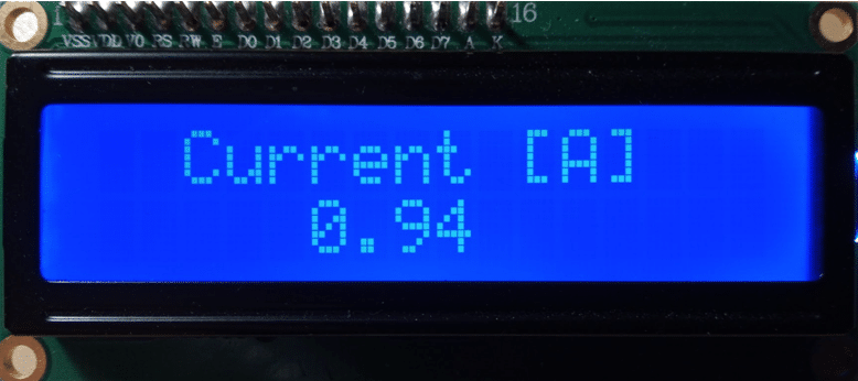
Remember to adjust the brightness of the LCD with the potentiometer on the back, if the letter are too bright or dark.
Setup Function
In the setup() function, the LCD display is initialized and the backlight is turned on to prepare for displaying the current measurements.
void setup() {
  lcd.init();
  lcd.backlight();
}
Loop Function
The loop() function and the remainder of the code are identical to the previous code.
void loop() {
  float cur = (vcc / 2 - vcc * avg()) / sens;
  display(cur);
}
And with that you have a DC current meter that displays the current measurements on an LCD.
If you need more help with connecting and running the LCD with an Arduino have a look at our tutorial on How to use a 16×2 character LCD with Arduino and Character I2C LCD with Arduino Tutorial (8 Examples).
In the next section we are going to use the ACS712 library to measure DC and AC currents.
Using the ACS712 library
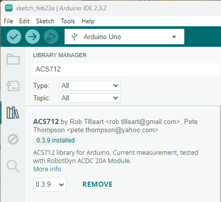
As you have seen above, measuring DC currents with the ACS712 is pretty simple and straightforward. Measuring AC currents, however, is a good deal more difficult and instead of implementing it ourselves, we are going to use the ACS712 library by RobTillaart. To install this library, open the library manager, search for ACS712 and press install.
This library has several functions that makes the calibration and measurement of DC and AC currents with the ACS712 very easy.
In the next sections, I introduce you to the library by replicating our DC current measurement from before but now using the ACS712 library. Then we change the code a tiny bit to measure AC currents. And finally, we are going to add the code to display our measurements on the LCD again.
Measuring DC Currents
Here is a simple example on how you can use the ACS712 library to measure DC currents.
#include "ACS712.h"

const float vcc = 5.0;
const int adcMax = 1023;
const int sens = 185;  // 5A

ACS712 ACS(A0, vcc, adcMax, sens);

void setup() {
  Serial.begin(9600);
  ACS.autoMidPoint();
}

void loop() {
  int cur = ACS.mA_DC();
  Serial.println(cur);
  delay(1000);
}
We first import the ACS712 Library and define the constants needed by the library.
Constants and Variables
The constant vcc represents the supply voltage (5.0V), adcMax is the maximum value of the analog-to-digital converter (1023), and sens is the sensitivity of the ACS712 sensor (185 for 5A). Note that sens = 185 instead of 0.185. Again, if you have a ACS712 sensor for a different current range, you have to change this constant.
const float vcc = 5.0;
const int adcMax = 1023;
const int sens = 185;  // 5A
ACS712 Instance
Next we create an instance of the ACS712 class called ACS with the specified parameters. Note that the sensor is connected to analog pin A0 on the Arduino board. And we use the parameters vcc, adcMax, and sens that were defined as constants above.
ACS712 ACS(A0, vcc, adcMax, sens);
In the setup() function, we initialize serial communication at a baud rate of 9600 and call the autoMidPoint() function of the ACS object to set the zero current point. This assumes that at start up the ACS712 sensor is not connected to any current source. Otherwise the calculated midpoint will be wrong. However, the library also provides functions to get and set the midpoint manually.
void setup() {
  Serial.begin(9600);
  ACS.autoMidPoint();
}
In the code before we assumed a midpoint at VCC/2. But in the presence of electromagnetic noise this might not always be the case. If so, you can get more accurate current readings by adjusting the mid point.
Loop Function
The loop() function continuously reads the DC current in milliamps using the mA_DC() method of the ACS object, prints the current value to the serial monitor, and then waits for 1 second before repeating the process. Note, that in contrast to the code before, here we are measuring milliampere and not ampere.
void loop() {
  int cur = ACS.mA_DC();
  Serial.println(cur);
  delay(1000);
}
As you can see the library makes the measurement of currents very simple and also automatically determines the midpoint, which will allow you measure positive and negative currents more accurately.
In the next section, we will make a very small code change to measure AC instead of DC currents.
Measuring AC Currents
As I mentioned before, measuring AC currents is a lot more complex then measuring DC currents, if you would implement this yourself. For more details have a look at this tutorial: Measure Any AC Current with ACS712.
However, with the ACS712 library, we just need to replace the function call ACS.mA_DC() by ACS.mA_AC(), to measure AC currents instead of DC currents. The remainder of the code, including the determination of the mid point remains the same. See the code below:
#include "ACS712.h"

const float vcc = 5.0;
const int adcMax = 1023;
const int sens = 185;  // 5A

ACS712 ACS(A0, vcc, adcMax, sens);

void setup() {
  Serial.begin(9600);
  ACS.autoMidPoint();
}

void loop() {
  int cur = ACS.mA_AC();  // AC
  Serial.println(cur);
  delay(1000);
}
Note that the ACS712 library has more functions and parameters to play with and to make your current readings as accurate as possible. The README is definitely worth reading.
Displaying Current on LCD
Finally, let us just add back the code to display current measurements on the LCD. There is really nothing new here, apart from using the ACS712 library and displaying the current in milliampere instead of ampere.
#include "ACS712.h"
#include "LiquidCrystal_I2C.h"

const float vcc = 5.0;
const int adcMax = 1023;
const byte lcdAdr = 0x3F;
const float sens = 185;    // 5A
//const float sens = 100;  // 20A
//const float sens = 66;   // 30A

ACS712 ACS(A0, vcc, adcMax, sens);
LiquidCrystal_I2C lcd = LiquidCrystal_I2C(lcdAdr, 16, 2);

void display(int cur) {
  lcd.clear();
  lcd.setCursor(2, 0);
  lcd.print("Current [mA]");
  lcd.setCursor(5, 1);
  lcd.print(cur);
}

void setup() {
  lcd.init();
  lcd.backlight();
  ACS.autoMidPoint();
}

void loop() {
  int cur = ACS.mA_DC();   // DC
  //int cur = ACS.mA_AC(); // AC
  display(cur);
  delay(1000);
}
Just remember to change the constants depending on which ACS712 current sensor you are using. Also switch between DC and AC by using ACS.mA_DC() or ACS.mA_AC().
Be careful, when using high voltages AC (e.g. 110 V) or high currents. High voltages can seriously injure you and high currents can cause fires!
Linearity and Accuracy of the ACS712
To test the linearity and accuracy of the ACS712, I used a regulate power supply with current limiter, a 8 Ohm, 100 Watt resistor and a Multimeter. You can see a picture of the setup below, which essentially is the measurement circuit described before.
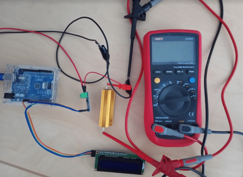
I set the power supply to 20V, changed the current limits to different values and recorded the corresponding ADC values. The graph below shows ADC value (0…1023) over current in Amperes (-2…2).
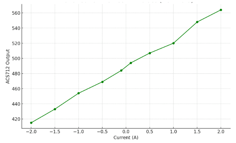
As you can see, the response is essentially linear (as expected) with some deviations, which were probably due to electromagnetic noise. Since the ACS712 is using a Hall Effect sensor it is susceptible to magnetic fields. You can easily verify this by placing a magnet close to the sensor and watch how the sensor output changes.
For robust readings you probably need to add some shielding around the sensor. I also had difficulties in finding a robust midpoint, so that negative and positive currents were measured accurately. The sensor is okay for approximate current readings but don’t expect great accuracy.
Conclusions
In this tutorial, we explored how to use the ACS712 current sensor with an Arduino to measure both DC and AC currents. By understanding the working principle of the ACS712 sensor and following the step-by-step guide for connecting it to an Arduino, you can now accurately measure currents in your projects.
By utilizing the provided code examples, you can easily read and display current data from the ACS712 sensor. Additionally, we demonstrated how to enhance your project by adding an LCD to display the current values in real-time, providing a more user-friendly interface.
Experiment with different current levels and explore the possibilities of incorporating this sensor into various applications.
Have fun and if you have any questions don’t hesitate to ask!
Frequently Asked Questions
How accurate is the ACS712 current sensor?
The ACS712 current sensor is known for its high accuracy in measuring currents, with typical sensitivity of 66mV/A for the ACS712-05B model and 185mV/A for the ACS712-30A model. However, keep in mind that external factors such as noise and interference can affect the sensor’s accuracy.
Can the ACS712 sensor measure both DC and AC currents?
Yes, the ACS712 current sensor is capable of measuring both DC and AC currents. It is a versatile sensor that can be used in various applications where current monitoring is required.
How can I calibrate the ACS712 sensor for accurate readings?
To calibrate the ACS712 sensor for accurate readings, you can use a known current source to compare the sensor readings with the actual current values. By adjusting the offset and sensitivity values in your code, you can ensure that the sensor provides precise measurements.
Is it possible to use multiple ACS712 sensors with a single Arduino?
Yes, you can use multiple ACS712 sensors with a single Arduino by connecting each sensor to a separate analog input pin on the Arduino. Make sure to adjust your code accordingly to read data from each sensor individually.
Can I use the ACS712 sensor with other microcontrollers besides Arduino?
Yes, the ACS712 sensor can be used with other microcontrollers besides Arduino, such as ESP32, Raspberry Pi, and more. As long as the microcontroller has analog input capabilities, you can interface the sensor with it to measure currents in your projects. Just remember to adjust the vcc and maxAdc constants, accordingly.
How do I interface the ACS712 sensor with an ESP32?
To interface the ACS712 sensor with an ESP32, connect the sensor’s output pin to one of the analog input pins on the ESP32. Then, read the analog input value in your ESP32 code to measure the current. Set vcc=3.3V and maxAdc = 4095.
Can I power the ACS712 sensor with a different voltage than the microcontroller?
Yes, you can power the ACS712 sensor with a different voltage than the microcontroller, as long as the sensor’s operating voltage range is respected. Be sure to check the datasheet for the sensor’s voltage requirements.
What is the maximum current that the ACS712 sensor can measure?
The ACS712 sensor is available in different models with varying current measurement ranges. The maximum current that the sensor can measure depends on the specific model you are using, such as 5A, 20A, or 30A.
How can I reduce noise and interference when using the ACS712 sensor?
To reduce noise and interference when using the ACS712 sensor, consider using proper decoupling capacitors, shielding the sensor’s connections, and keeping signal wires away from high-power lines or sources of electromagnetic interference.
Is it possible to use the ACS712 sensor in high-voltage applications?
The ACS712 sensor is designed for low-voltage applications and should not be used in high-voltage environments. If you need to measure high currents in high-voltage circuits, consider using current sensors specifically rated for those conditions.
Can I use the ACS712 sensor to measure bi-directional currents?
Yes, the ACS712 sensor can measure bi-directional currents, as it is capable of detecting both positive and negative current flows. By interpreting the sensor readings in your code, you can determine the direction of the current flow.
How can I protect the ACS712 sensor from overcurrent situations?
To protect the ACS712 sensor from overcurrent situations, you can incorporate a current-limiting circuit or fuse in your circuit design. This will help prevent the sensor from being damaged in case of excessive current flow.
Can I use the ACS712 sensor in automotive applications?
Yes, the ACS712 sensor can be used in automotive applications to monitor currents in various systems such as battery management, motor control, and lighting. Ensure that the sensor is properly calibrated and meets the voltage and current requirements of the automotive system.
What is the response time of the ACS712 sensor?
The response time of the ACS712 sensor is relatively fast, typically in the range of microseconds. This makes it suitable for applications where real-time current monitoring is required.
Can I use the ACS712 sensor in high-temperature environments?
The ACS712 sensor has a specified operating temperature range, typically between -40°C to 85°C. It is not recommended to use the sensor in environments exceeding this temperature range, as it may affect its accuracy and performance.
How can I enhance the resolution of current measurements with the ACS712 sensor?
To enhance the resolution of current measurements with the ACS712 sensor, you can amplify the sensor’s output signal using an operational amplifier (op-amp) circuit. This can help increase the sensitivity and precision of the current readings.
Can I use the ACS712 sensor for battery monitoring applications?
Yes, the ACS712 sensor can be used for battery monitoring applications to measure the current flowing in and out of a battery. By integrating the sensor into your battery management system, you can track the battery’s charging and discharging currents.
What is the typical accuracy of the ACS712 sensor over its operating range?
The ACS712 sensor typically offers accuracy within a few percentage points over its specified operating range. However, factors such as temperature variations and external interference can impact the sensor’s overall accuracy.
How can I power the ACS712 sensor using a battery?
You can power the ACS712 sensor using a battery by connecting the sensor’s VCC pin to the positive terminal of the battery and the GND pin to the negative terminal. Ensure that the battery voltage falls within the sensor’s operating voltage range.
What is the difference between the ACS712 models with different current ratings?
The ACS712 models with different current ratings, such as 5A, 20A, and 30A, have varying sensitivity levels and measurement ranges. The higher the current rating, the lower the sensitivity and the wider the measurement range of the sensor.
How can I implement overcurrent protection using the ACS712 sensor?
To implement overcurrent protection using the ACS712 sensor, you can set a threshold value in your code beyond which an alarm or shutdown mechanism is triggered. By continuously monitoring the current readings from the sensor, you can detect and respond to overcurrent situations effectively.
Can I use the ACS712 sensor for motor control applications?
Yes, the ACS712 sensor can be used for motor control applications to monitor the current drawn by the motor. By measuring the motor current, you can implement feedback control mechanisms to regulate the motor’s speed and torque.
How can I calculate power consumption using the ACS712 sensor?
To calculate power consumption using the ACS712 sensor, multiply the measured current value by the voltage across the load. This will give you the instantaneous power consumption at that moment. By integrating these power values over time, you can determine the total energy consumed.

I am Puneeth. I love tinkering with open-source projects, Arduino, ESP32, Pi and more. I have worked with many different Arduino boards and currently I am exploring, Arduino powered LoRa, Power line communication and IoT.
Peter
Saturday 20th of January 2024
I tried this sensor and compared its output against that of an avometer. It provides real results with all devices except only one device, which is the vacuum cleaner. I don’t know why. The vacuum cleaner current on the avometer 5.5 amp But what the Surreal Monitor shows me is 7.5 amp
Jayme
Wednesday 10th of January 2024
Seems your code samples for 5A and 20A is the same?
Stefan Maetschke
Wednesday 10th of January 2024
The two code samples are almost identical apart from the sensitivity constant (0.100 vs 0.185). I added an specific constant to make that clearer. Thanks