In this tutorial, I will provide the essential details about the air quality index, the pinout of the MQ-135 sensor, and how to measure air pollution using the MQ-135 sensor.
After this tutorial, you will be able to develop the air pollution monitoring and alert system using the Arduino Uno board with an MQ-135 sensor.
Hardware components
| Arduino Uno Rev3 | x1 | Amazon |
| Arduino Mega (Optional) | x1 | Amazon |
| MQ-135 Air Quality Sensor | x1 | Amazon |
| 16 x 2 LCD Display | x1 | Amazon |
| LED | x3 | Amazon |
| Buzzer | x1 | Amazon |
| Breadboard | x1 | Amazon |
| Jumper wires | x15 | Amazon |
| 10K Potentiometer | x1 | Amazon |
| USB cable type A/B | x1 | Amazon |
Software
| Arduino IDE | Arduino IDE |
Makerguides.com is a participant in the Amazon Services LLC Associates Program, an affiliate advertising program designed to provide a means for sites to earn advertising fees by advertising and linking to products on Amazon.com.
What is air pollution?
Air pollution is the presence of excessive amounts of undesirable and unsafe solid or gaseous substances such as Carbon Monoxide, Lead, Nitrogen Oxide, Ozone, Particulate Matter, Sulfur Dioxide, etc., atmosphere.
Air pollution cause and effect
Air pollution has become an increasingly hazardous problem over the past few years. This factor is directly related to human health.
Global warming has become a severe concern for many countries; one widely faced issue is air pollution.
Other effects of air pollution also include various diseases like lung cancer, ischemic heart disease, asthma attacks, etc.
What is an air pollution monitoring system?
The Air pollution monitoring system is a facility to measure air pollutants using sensors, processing using microcontrollers, and showing results using various displays.
How can air pollution be monitored?
Air quality is a measure of how clean or polluted the air is. Air pollution is usually measured as Air Quality Index (AQI) in the PPM unit.
The sensors are most suitable for identifying hotspots at roadsides and near point sources. This sensor gets data that can be continuously monitored via different displays.
| Air Quality Index (AQI) Values | Levels of Health Concern | Air Quality Index (AQI) Values | Qualitative name |
| 0 to 50 | Good | 0 to 25 | Very low |
| 51 to 100 | Moderate | 25 to 50 | Low |
| 101 to 150 | Unhealthy for Sensitive Groups | 50 to 75 | Medium |
| 151 to 200 | Unhealthy | 75 to 100 | High |
| 201 to 300 | Very Unhealthy | >100 | Very high |
| 301 to 500 | Hazardous |
Air Quality Index: Source
What sensor can detect air pollution?
Nowadays, progress in electronics parts and availability of various sensors like MQ-135, MQ-2, MQ-3, MQ-4, MQ-5, MQ-6, etc., to measure the air pollutant, different systems are developed to monitor the number of air pollutants in the air.
MQ135 is one of the most popular sensors for measuring AQI in PPM.
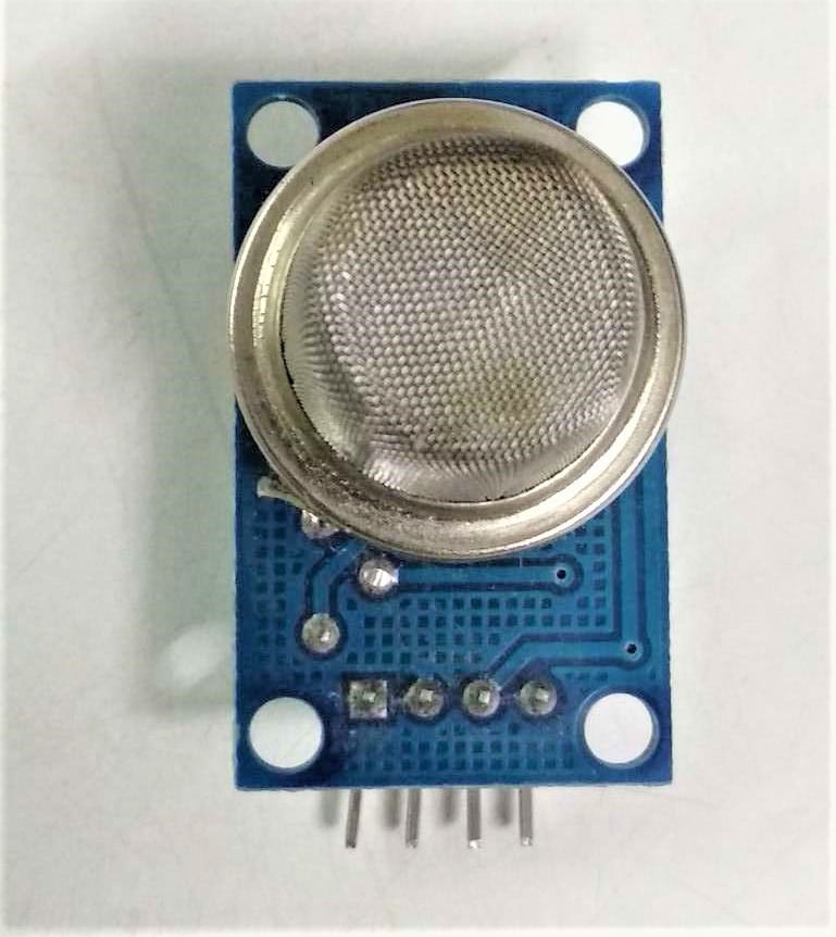
What is the MQ-135 sensor?
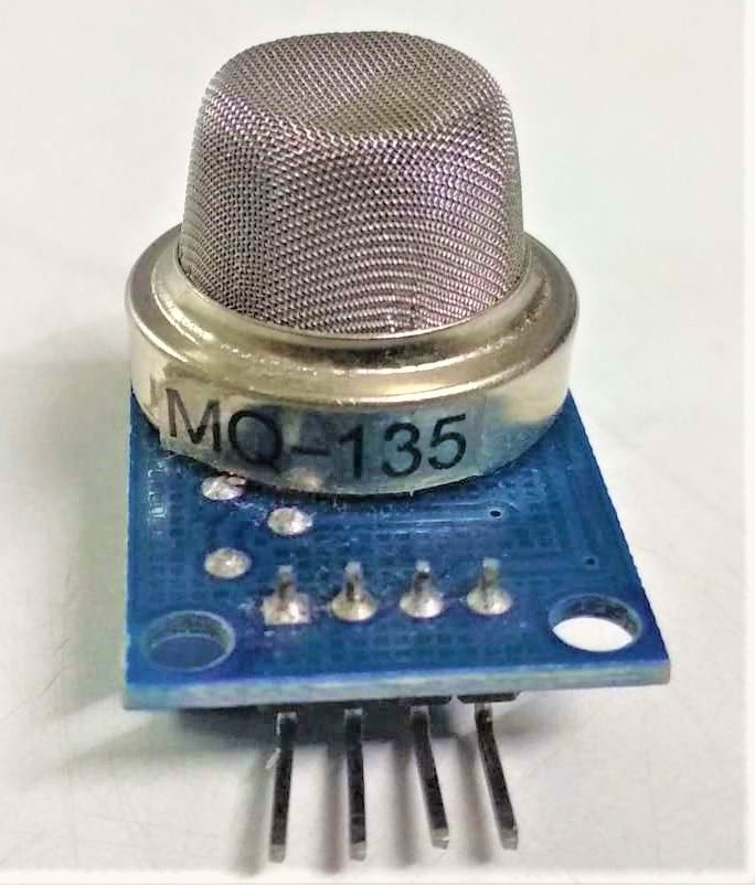
MQ-135 is a gas sensor that has lower conductivity in clean air. It is low cost and suitable for different applications.
This module operates at 5V, has 33Ω±5% resistance, and consumes around 150mA.
This sensor has four pins from four pins, Digital and Analog output pins, which are used to approximate these gasses levels in the atmosphere.
When these gasses go beyond a threshold limit in the air, the digital pin rises.
This threshold value can be set by using the onboard potentiometer.
Features of MQ-135 Sensor
- Wide detecting scope, Fast response, and High sensitivity
- Long lifespan
- Heater Voltage: 5.0V
- It contains analog output and high/low digital output
- The TTL output signal is a low level
- The operating Voltage is +5V
- Detected/Measure NH3, NOx, alcohol, Benzene, smoke, CO2, etc.
- Detection Range: 10 – 300 ppm NH3, 10 – 1000 ppm Benzene, 10 – 300 Alcohol
If you want more details about the MQ-135 sensor, refer to the MQ-135 datasheet and MQ-135 Schematic pdf.
Working Mechanism
Now, let’s understand the working mechanism of the MQ-135 gas sensor.
The MQ-135 Gas sensor consists of Tin Dioxide (SnO2). When target pollution gas exists, the sensor’s conductivity increases along with the gas concentration.
Users can convert the change of conductivity to correspond to the output signal of gas concentration through a simple circuit.
The MQ-135 gas sensor has a high sensitivity to NH3, S2, C6H6 series steam and can monitor smoke and other toxic gasses. It can detect kinds of toxic gasses.
Pinout of MQ135
The MQ-135 sensor module has four pins, with the most important part being an adjustable potentiometer.
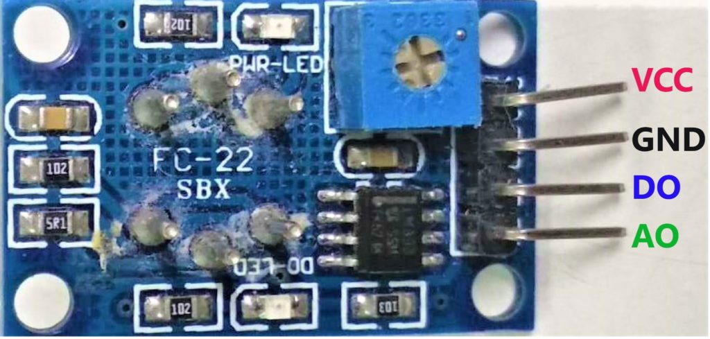
| Pin number | Pin name | Details |
| 1 | VCC Pin | The Pin requires 5V to power the module. |
| 2 | Ground Pin | To connect the module to the system’s common Ground |
| 3 | Digital Output Pin | This pin sets the threshold value by using a potentiometer. |
| 4 | Analog Output Pin | The analog voltage pin is based on the concentration of the gas. |
Can air quality be measured with an Arduino device?
Arduino Uno consists of 14 digital input/output (I/O) pins and 6 analog input pins, which fulfill the requirement of the AQI monitoring system.
This system could be extended by various modules compatible with Arduino, such as Ethernet shield, GSM/GPRS shield, GPS logger shield, RTC shield, and built-in board with VCC, Ground, etc.
Now you know quite a bit about the MQ-135 sensor, let’s move ahead and learn how to interface the MQ-135 with Arduino.
Wiring MQ-135 sensor with Arduino UNO
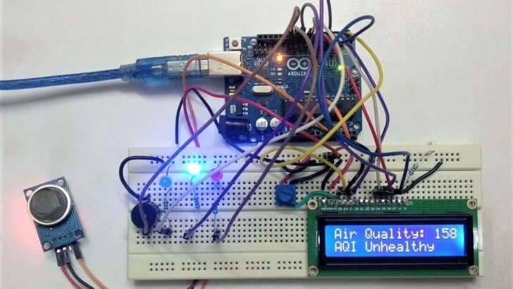
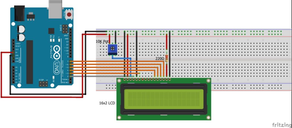
This circuit diagram is self-explanatory. The best way to interface this circuit is to start with an Arduino Uno board and LCD with the breadboard.
Step 1: First, place a 16×2 LCD on the breadboard, as shown in the figure.
Now, connect A to +5V with a 220-ohm resistor and K to Ground.
To vary the contrast of a 16×2 LCD, connect the VO to the middle pin of the potentiometer and VDD to +5V, VSS & RW to Ground.
Also, provide +5V and Ground to the potentiometer as depicted in the figure.
The summary of connections is mentioned in the below table.
| Arduino Uno PIN | 16×2 LCD Pin |
| Digital Pin 2 | RS |
| Digital Pin 3 | EN |
| Digital Pin 4 | D4 |
| Digital Pin 5 | D5 |
| Digital Pin 6 | D6 |
| Digital Pin 7 | D7 |
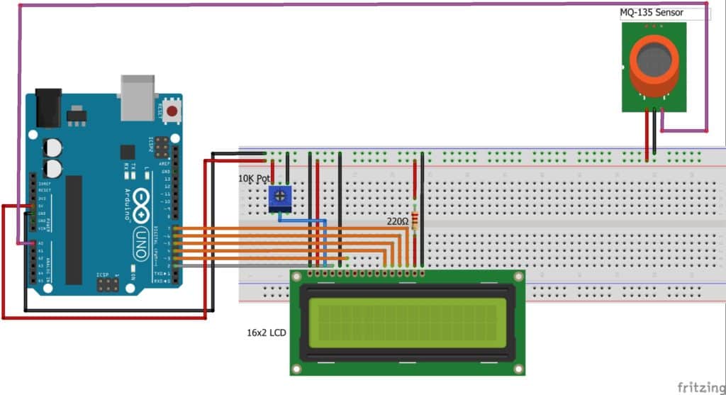
Step 2: The MQ-135 module connects to the A0 pin of an Arduino Uno and connects GND to Ground, providing +5V to VCC.
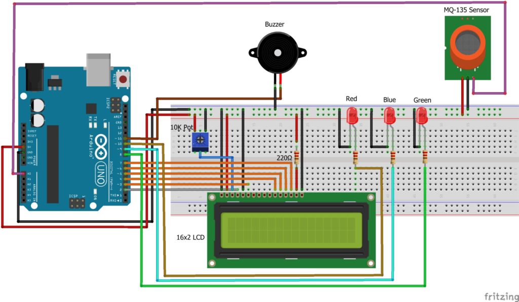
Step 3: Connect Anode (+) of Green LED to digital pin 8 of Arduino; Blue LED to digital 9 pin of Arduino and Red LED to digital pin 10 of Arduino and all LEDs Cathode (-) Ground with 220-ohm resistor.
Step 4: Connect the buzzer’s positive terminal to digital pin 11 of Arduino and the negative terminal to the ground.
Arduino Code For Air Pollution Monitoring
The following code allows you to measure the air pollutant in the air in a PPM unit using the MQ-135 sensor.
You can see the results on a serial monitor and a 16×2 LCD.
// Include library for LCD and define pins
#include "LiquidCrystal.h"

const int rs = 2, en = 3, d4 = 4, d5 = 5, d6 = 6, d7 = 7;
LiquidCrystal lcd(rs, en, d4, d5, d6, d7);

// Define pins and variable for input sensor and output led and buzzer
const int mq135_aqi_sensor = A0;
const int green_led = 8;
const int blue_led = 9;
const int red_led = 10;
const int buzzer = 11;

// Set threshold for AQI
int aqi_ppm = 0;

void setup() {
  // Set direction of input-output pins
  pinMode (mq135_aqi_sensor, INPUT);
  pinMode (green_led, OUTPUT);
  pinMode (blue_led, OUTPUT);
  pinMode (red_led, OUTPUT);
  pinMode (buzzer, OUTPUT);

  digitalWrite(green_led, LOW);
  digitalWrite(blue_led, LOW);
  digitalWrite(red_led, LOW);
  digitalWrite(buzzer, LOW);

  // Initiate serial and lcd communication
  Serial.begin (9600);
  lcd.clear();
  lcd.begin (16, 2);

  Serial.println("AQI Alert System");
  lcd.setCursor(0, 0);
  lcd.print("AQI Alert System");
  delay(1000);
}

void loop() {
  aqi_ppm = analogRead(mq135_aqi_sensor);

  Serial.print("Air Quality: ");
  Serial.println(aqi_ppm);

  lcd.setCursor(0, 0);
  lcd.print("Air Quality: ");
  lcd.print(aqi_ppm);

  if ((aqi_ppm >= 0) && (aqi_ppm <= 50))
  {
    lcd.setCursor(0, 1);
    lcd.print("AQI Good");
    Serial.println("AQI Good");
    digitalWrite(green_led, HIGH);
    digitalWrite(blue_led, LOW);
    digitalWrite(red_led, LOW);
    digitalWrite(buzzer, LOW);
  }
  else if ((aqi_ppm >= 51) && (aqi_ppm <= 100))
  {
    lcd.setCursor(0, 1);
    lcd.print("AQI Moderate");
    Serial.println("AQI Moderate");
    tone(green_led, 1000, 200);
    digitalWrite(blue_led, HIGH);
    digitalWrite(red_led, LOW);
    digitalWrite(buzzer, LOW);
  }

  else if ((aqi_ppm >= 101) && (aqi_ppm <= 200))
  {
    lcd.setCursor(0, 1);
    lcd.print("AQI Unhealthy");
    Serial.println("AQI Unhealthy");
    digitalWrite(green_led, LOW);
    digitalWrite(blue_led, HIGH);
    digitalWrite(red_led, LOW);
    digitalWrite(buzzer, LOW);
  }
  else if ((aqi_ppm >= 201) && (aqi_ppm <= 300))
  {
    lcd.setCursor(0, 1);
    lcd.print("AQI V. Unhealthy");
    Serial.println("AQI V. Unhealthy");
    digitalWrite(green_led, LOW);
    tone(blue_led, 1000, 200);
    digitalWrite(red_led, HIGH);
    digitalWrite(buzzer, LOW);
  }
  else if (aqi_ppm >= 301)
  {
    lcd.setCursor(0, 1);
    lcd.print("AQI Hazardous");
    Serial.println("AQI Hazardous");
    digitalWrite(green_led, LOW);
    digitalWrite(blue_led, LOW);
    digitalWrite(red_led, HIGH);
    digitalWrite(buzzer, HIGH);
  }
  delay (700);
}
How The Code Works
I have used an Arduino IDE to program an Arduino Uno board.
Step 1: First, I have included the necessary header file for 16×2 LCD,
#include "LiquidCrystal.h>" // Header file for LCD
Step 2: Define the variables for different pins used in the Arduino board for LCD, Buzzer, LED, and MQ-135. Also, define the variable for analog value.
const int rs = 2, en = 3, d4 = 4, d5 = 5, d6 = 6, d7 = 7;   // LCD to Arduino pins
LiquidCrystal lcd(rs, en, d4, d5, d6, d7);   // LiquidCrystal function

const int mq135_aqi_sensor = A0;      // Connect MQ-135 sensor to A0 pin of Arduino
const int green_led = 8;                       // Connect green LED to digital 8 pin of Arduino
const int blue_led = 9;                         // Connect blue LED to digital 9 pin of Arduino
const int red_led = 10;                        // Connect red LED to digital 10 pin of Arduino
const int buzzer = 11;                         // Connect buzzer to digital 11 pin of Arduino

int aqi_ppm = 0;                       	     // Initialize the variable for catch up analog value
Step 3: In the void setup() function, I have initialized the Buzzer, LED as an output device, and MQ-135 as an input device to Arduino Uno.
lcd.begin(); function initialize 16×2 LCD, before initializing the 16×2 LCD you must clear.
Using lcd.clear(); function. Also, set the baud rate at 9600-speed rate using Serial.begin(); function.
Step 4: After Initialize,16×2 LCD in set the cursor home position.
lcd.setCursor(0, 0);
The below message will print on the serial terminal and 16×2 LCD.
Serial.println(“AQI Alert System”);
lcd.print(“AQI Alert System”);
Step 5: In void loop() function, initializing the variable to catch up analog value, using analogRead(); function. And print on message serial terminal and 16×2 LCD.
aqi_ppm = analogRead(mq135_aqi_sensor);
Serial.print("Air Quality: ");
Serial.println(aqi_ppm);

lcd.setCursor(0, 0);
lcd.print("Air Quality: ");
lcd.print(aqi_ppm);
Step 6: If the Suppose Analog value is between 0 to 50, the green LED will blink. Print on message serial terminal. And on LCD will print a message in the second row and first position.
    lcd.setCursor(0, 1);
    lcd.print("AQI Good");
    Serial.println("AQI Good");
    digitalWrite(green_led, HIGH);
Step 7: Same as, depending on AQI value, LED will blink and print on the message serial terminal and the 16×2 LCD following the table.
| AQI value | Green LED | Blue LED | Red LED | Buzzer | Serial Terminal and16×2 LCD Message |
| 0 – 50 | ON | OFF | OFF | OFF | AQI Good |
| 51 – 100 | BLINK | ON | OFF | OFF | AQI Moderate |
| 101 – 200 | OFF | ON | OFF | OFF | AQI Unhealthy |
| 201 – 300 | OFF | BLINK | ON | OFF | AQI Very Unhealthy |
| > 301 | OFF | OFF | ON | ON | AQI Hazardous |
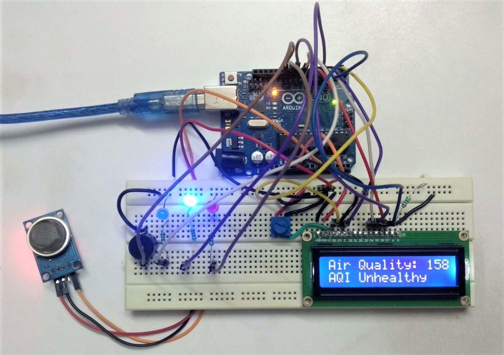
LCD Output:
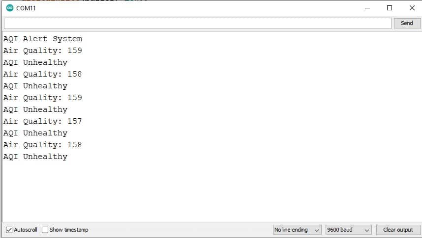
Serial Monitor Output:
Conclusion
After this tutorial, you can develop your own Air Monitoring and Alert System using the MQ-135 sensor and Arduino Uno board.
I hope you found this tutorial informative. If you did, please share it with a friend who likes electronics and making things!
I would love to know what project you plan on building or have already made with the Arduino.
If you have any questions or suggestions or think things are missing in this tutorial, please leave a comment below.

Hiren is a professional Embedded Engineer with a Master’s Degree
in Electronics and Communication Engineering. He is proficient in C and
C++ and enjoys building DIY projects on Arduino, ESP32, PIC32, STM32 & Raspberry PI boards.
Shelke Snehal
Saturday 9th of March 2024
Thank you so much
Jakub
Saturday 19th of August 2023
This code is terrible! Can't do "copy paste"!
Stefan
Saturday 19th of August 2023
hmm, works for me. I clicked "copy to clipboard" in the right upper corner and the copy worked. What Browser are you using? I am on Chrome.
Chackochan Sebastian
Thursday 1st of June 2023
Is there a need to calibrate the mq135 sensor for this project? If yes, can you tell me how?
성인망가
Thursday 26th of January 2023
Hello there! I simply wish to give you a huge thumbs up for the great info you have got right here on this post "성인망가"Does running a blog like this take a large attention-grabbing discussion is worth comment. It’s difficult to find knowledgeable people using the same blog platform.