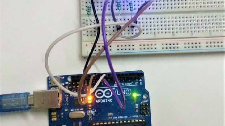
In this tutorial, you will learn essential information about a Light-Emitting Diode (LED) and how to control multiple LEDs with Arduino.
Using an Arduino Uno board, you will learn how to implement a project controlling multiple LEDs with different delays.
Required Parts

Arduino Uno

USB Cable for Arduino UNO

Dupont Wire Set

Breadboard

Resistor & LED kit
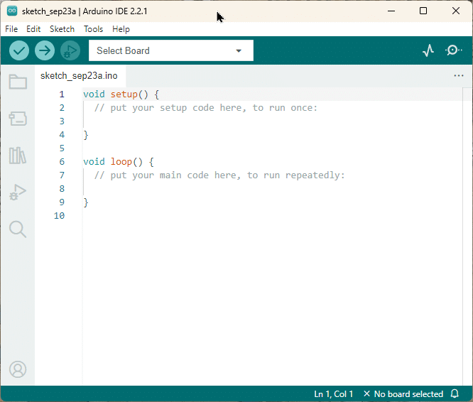
Arduino IDE
Makerguides.com is a participant in the Amazon Services LLC Associates Program, an affiliate advertising program designed to provide a means for sites to earn advertising fees by advertising and linking to products on Amazon.com. As an Amazon Associate we earn from qualifying purchases.
What is a Light Emitting Diode (LED)?

A Light-emitting diode (LED) is a small semiconductor device, Which can emit light when an electric current flows through it.
When current passes through an LED, electrons in the semiconductor recombine with an electron-hole and release energy in the form of photons.
LEDs allow the current to flow forward and block the current in the reverse direction.
LEDs are used in many different applications, such as TV Backlighting, Automotive Lighting, and Smartphone Backlighting.
How Do You Control Multiple LED Lights
An Arduino can theoretically control as many LEDs as you require for your design, only limited by the power supply current available.
However, if you want to control more LEDs than digital pins on your Arduino board, you need to use some additional hardware.
I am using 3 LEDs with an Arduino Uno board, as shown in the wiring diagram.
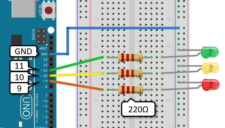
Wiring Diagram
Step 1: Connect the LEDs anode (+) to a digital pin of the Arduino pin mentioned in the table below with a 220 Ohm resistor.
Connect the LEDs as per the following table.
| LED | Arduino Pin |
| GREEN | Digital Pin 11 |
| YELLOW | Digital Pin 10 |
| RED | Digital Pin 9 |
Step 2: Connect all the LEDs cathode (-) to GND.
Arduino Code
Following Arduino code is used to control the three LEDs with different delays.
#define Blink_LED_1 11
#define Blink_LED_2 10
#define Blink_LED_3 9

void setup()
{
  Serial.begin(9600);
  pinMode(Blink_LED_1, OUTPUT);
  pinMode(Blink_LED_2, OUTPUT);
  pinMode(Blink_LED_3, OUTPUT);
}

void loop()
{
  digitalWrite(Blink_LED_1, HIGH);
  digitalWrite(Blink_LED_2, LOW);
  digitalWrite(Blink_LED_3, LOW);
  Serial.println("LED_1 ON");
  delay(3000);

  digitalWrite(Blink_LED_1, LOW);
  digitalWrite(Blink_LED_2, HIGH);
  digitalWrite(Blink_LED_3, LOW);
  Serial.println("LED_2 ON");
  delay(2000);

  digitalWrite(Blink_LED_1, LOW);
  digitalWrite(Blink_LED_2, LOW);
  digitalWrite(Blink_LED_3, HIGH);
  Serial.println("LED_3 ON");
  delay(1000);
}
How The Code Works
Step 1: First, define the digital Pin for LEDs as per the wiring diagram.
#define Blink_LED_1  11
#define Blink_LED_2  10
#define Blink_LED_3  9
Step 2:
void setup()
{
  Serial.begin(9600);
  pinMode(Blink_LED_1, OUTPUT);
  pinMode(Blink_LED_2, OUTPUT);
  pinMode(Blink_LED_3, OUTPUT);
}
In the void setup() function, LEDs are set as an OUTPUT mode using pinMode(); function. Initialize the serial communication using Serial.begin() function.
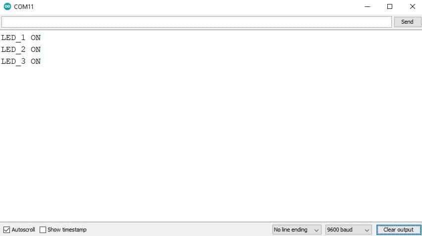
Step 3: In the void loop() function, Blink the LEDs, and the result shows on the serial terminal as follows in the table.
| Blink_LED_1 | Blink_LED_2 | Blink_LED_3 | Duration | Serial Terminal Message |
| ON | OFF | OFF | 3 second | LED_1 ON |
| OFF | ON | OFF | 2 second | LED_2 ON |
| OFF | OFF | ON | 1 second | LED_3 ON |
Output On The Serial Terminal
Using millis () Function To Control Multiple LEDs
Using the millis() function, you can set the required delay. The following code will help you understand how to use millis() to control multiple LEDs.
Arduino Code
This code generates the different delays using the millis() function to control the multiple LEDs at different rates.
// Which pins are connected to which LED
#define Blink_LED_1 11
#define Blink_LED_2 10
#define Blink_LED_3 9

// Assign flags for status of LEDs
volatile int blink_LED_1_flag = 0;
volatile int blink_LED_2_flag = 0;
volatile int blink_LED_3_flag = 0;

//Assign delays intervals for different LEDs
const unsigned long Blink_LED_1_interval = 1000;
const unsigned long Blink_LED_2_interval = 2000;
const unsigned long Blink_LED_3_interval = 3000;

// Declaring the variables holding the timer values for each LED.
unsigned long Blink_LED_1_timer = 0;
unsigned long Blink_LED_2_timer = 0;
unsigned long Blink_LED_3_timer = 0;

// Setting 3 digital pins direction as output
void setup() {
  Serial.begin(9600);
  pinMode(Blink_LED_1, OUTPUT);
  pinMode(Blink_LED_2, OUTPUT);
  pinMode(Blink_LED_3, OUTPUT);
}

void toggle_LED1() {
  if (blink_LED_1_flag == 0) {
    digitalWrite(Blink_LED_1, HIGH);
    blink_LED_1_flag = 1;
  } else {
    digitalWrite(Blink_LED_1, LOW);
    blink_LED_1_flag = 0;
  }
  Serial.println("LED_1 Toggle");
  Blink_LED_1_timer = millis();  // stores current value of millis()
}

void toggle_LED2() {
  if (blink_LED_2_flag == 0) {
    digitalWrite(Blink_LED_2, HIGH);
    blink_LED_2_flag = 1;
  } else {
    digitalWrite(Blink_LED_2, LOW);
    blink_LED_2_flag = 0;
  }
  Serial.println("LED_2 Toggle");
  Blink_LED_2_timer = millis();  // stores current value of millis()
}

void toggle_LED3() {
  if (blink_LED_3_flag == 0) {
    digitalWrite(Blink_LED_3, HIGH);
    blink_LED_3_flag = 1;
  } else {
    digitalWrite(Blink_LED_3, LOW);
    blink_LED_3_flag = 0;
  }
  Serial.println("LED_3 Toggle");
  Blink_LED_3_timer = millis();  // stores current value of millis()
}

void loop() {
  if ((millis() - Blink_LED_1_timer) >= Blink_LED_1_interval) {
    toggle_LED1();
  }
  if ((millis() - Blink_LED_2_timer) >= Blink_LED_2_interval) {
    toggle_LED2();
  }
  if ((millis() - Blink_LED_3_timer) >= Blink_LED_3_interval) {
    toggle_LED3();
  }
}
How The Code Works
In this code, Using the millis() function LED will turn ON and turn OFF. There is no blocking condition here.
First, define the digital pins for LEDs as per the wiring diagram.
#define Blink_LED_1  11
#define Blink_LED_2  10
#define Blink_LED_3  9
Next, I will use variables for different LEDs to store the current status LEDs.
// Assign flags for status of LEDs
volatile int blink_LED_1_flag = 0;
volatile int blink_LED_2_flag = 0;
volatile int blink_LED_3_flag = 0;
Then define the variable to store the value of different delays for LEDs.
const unsigned long Blink_LED_1_interval = 1000;
const unsigned long Blink_LED_2_interval = 2000;
const unsigned long Blink_LED_3_interval = 3000;
Followed by declaring the variables holding the timer values for each LED, initializing with zero.
unsigned long Blink_LED_1_timer=0;
unsigned long Blink_LED_2_timer=0;
unsigned long Blink_LED_3_timer=0;
In the void setup() function, LEDs are set as an OUTPUT mode using pinMode() function.
I have also initialized the serial monitor with a 9600 baud rate.
Arduino’s millis() function returns the number of milliseconds the program has started running.
Here, Assign the millis (); values in the timer variable.
void setup ()
{
  Serial.begin(9600);
  pinMode(Blink_LED_1, OUTPUT);
  pinMode(Blink_LED_2, OUTPUT);
  pinMode(Blink_LED_3, OUTPUT);
}
Finally, I have used the toggle LED function to check the current status of the LED with the help of the flag variable.
If the flag is zero, it will turn ON the LED; otherwise, if the flag is one, it will turn OFF the LED.
In the end, the respective LED timer is also updated to the current time.
void toggle_LED1() {
  if (blink_LED_1_flag == 0) {
    digitalWrite(Blink_LED_1, HIGH);
    blink_LED_1_flag = 1;
  } else {
    digitalWrite(Blink_LED_1, LOW);
    blink_LED_1_flag = 0;
  }
  Serial.println("LED_1 Toggle");
  Blink_LED_1_timer = millis();  // stores current value of millis()
}

void toggle_LED2() {
  if (blink_LED_2_flag == 0) {
    digitalWrite(Blink_LED_2, HIGH);
    blink_LED_2_flag = 1;
  } else {
    digitalWrite(Blink_LED_2, LOW);
    blink_LED_2_flag = 0;
  }
  Serial.println("LED_2 Toggle");
  Blink_LED_2_timer = millis();  // stores current value of millis()
}

void toggle_LED3() {
  if (blink_LED_3_flag == 0) {
    digitalWrite(Blink_LED_3, HIGH);
    blink_LED_3_flag = 1;
  } else {
    digitalWrite(Blink_LED_3, LOW);
    blink_LED_3_flag = 0;
  }
  Serial.println("LED_3 Toggle");
  Blink_LED_3_timer = millis();  // stores current value of millis()
}
In void loop(), The LED will toggle when the condition is true.
Here, millis(); function stores the current time.
Blink_LED_2_timer variable is saved the last time you blinked the LED2.
I am using the Blink_LED_2_interval time variable, a predefined delay for LED2.
There are no blocking conditions. Many times this code will execute in a second. LEDs will toggle as per the time interval variables.
void loop () {
  if ( (millis () - Blink_LED_1_timer) >= Blink_LED_1_interval)
    toggle_LED1 ();

  if ( (millis () - Blink_LED_2_timer) >= Blink_LED_2_interval)
    toggle_LED2 ();

  if ( (millis () - Blink_LED_3_timer) >= Blink_LED_3_interval)
    toggle_LED3 ();
}
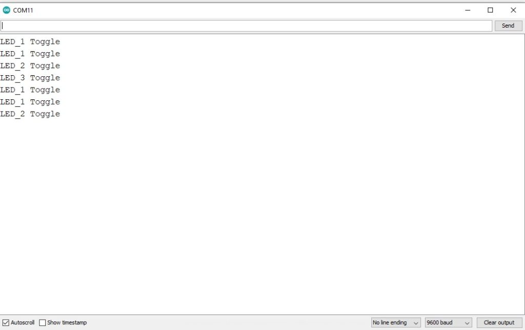
Output On The Serial Monitor
How do you blink two LEDs at different rates?
You can blink two LEDs at different rates using the delay function or millis(). You can set different delays for both LEDs.
For example, for LED1, you can use delay(1000), and for LED2, delay(2000).
Thus, with different delays, both LEDs will blink at different rates.
Conclusion
This article shows you how to control 3 LEDs with different delay functions and without delays. You will have noticed that it is actually quite complex to blink LEDs independently.
However, instead of writing your own code, you could also use existing libraries such as ezOutput, that simplify this task. For more details have a look at the our tutorial: Blink LEDs with different Frequencies.
If you have any queries or suggestions or think things are missing in this tutorial, please leave a comment below.

Hiren is a professional Embedded Engineer with a Master’s Degree
in Electronics and Communication Engineering. He is proficient in C and
C++ and enjoys building DIY projects on Arduino, ESP32, PIC32, STM32 & Raspberry PI boards.
David
Tuesday 9th of April 2024
hello , what is Delay high and low for this frequencies : 5 hz 5,5 hz 25 hz and 40 hz because i want to blinking LED with this frequencies and it is possible to blinking LED with 2 frequencies 5 hz in left and 25 hz in right
Stefan Maetschke
Sunday 14th of April 2024
For more details have a look at the following tutorial: https://www.makerguides.com/blink-leds-different-frequencies-arduino/
Stefan Maetschke
Thursday 11th of April 2024
Hi, I would use the ezOutput library for that. Here is a code example for three leds blinking with 5Hz, 5.5Hz and 40Hz, with a duty cycle of 50%:
#include "ezOutput.h"
ezOutput led1(11); ezOutput led2(10); ezOutput led3(9);
void setup() { float f5 = 5; float f5_5 = 5.5; float f40 = 40;
led1.blink(1000/f5/2, 1000/f5/2); led2.blink(1000/f5_5/2, 1000/f5_5/2); led3.blink(1000/f40/2, 1000/f40/2); }
void loop() { led1.loop(); led2.loop(); led3.loop(); }