If you are looking for the specifications, pinout, fritzing model, datasheet, or comparison of an Arduino Nano board, then you have come to the right place!
This article includes everything you need to know about each of the 5 currently available Arduino Nano boards. If you have any questions, please leave a comment below.
Recommended articles
- How to use an IR receiver and remote with Arduino
- The complete guide for DS18B20 digital temperature sensors with Arduino
- How to control servo motors with Arduino
- MAX7219 LED dot matrix display Arduino tutorial
Arduino Nano
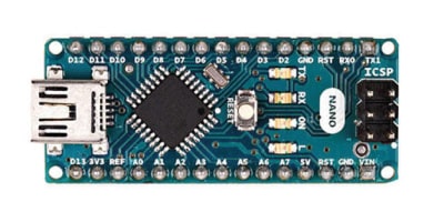
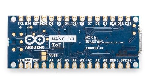
The Arduino Nano was first released in 2008 and is still one of the most popular Arduino boards available. The Nano is a breadboard-friendly board, based on the ATmega328 8-bit microcontroller by Atmel (Microchip Technology). It has more or less the same functionality as the Arduino Uno but in a smaller form factor. The only thing that is missing is a DC power jack and it works with a Mini-B USB cable instead of a standard one.
The specifications of the latest version of the Arduino Nano can be found below.
Arduino Nano specifications
| Microcontroller | ATmega328 |
| Operating voltage | 5 V |
| Input voltage (VIN) | 6-20 V |
| Power consumption | 19 mA |
| Flash memory | 32 KB of which 2 KB is used by bootloader |
| SRAM | 2 KB |
| Clock speed | 16 Mhz |
| EEPROM | 1 KB |
| DC current per I/O pin | 40 mA (20 mA recommended) |
| Digital I/O pins | 22 |
| PWM outputs | 6 (D3, D5, D6, D9, D10, D11) |
| Analog input pins | 8 (ADC 10 bit) |
| I2C | A4 (SDA), A5 (SCL) |
| SPI | D10 (SS), D11 (MOSI), D12 (MISO), D13 (SCK) |
| LED_BUILTIN | D13 |
| PCB size | 18 x 45 mm |
| Weight | 7 g |
| Cost | Check price |
If you want to compare the specifications and functionality of this board with the other boards of the Arduino Nano family, check out the comparison table at the end of this article.
The Arduino Nano is open-source hardware! You can download the schematics for this board here:
The Fritzing model of the Arduino Nano can be found here:
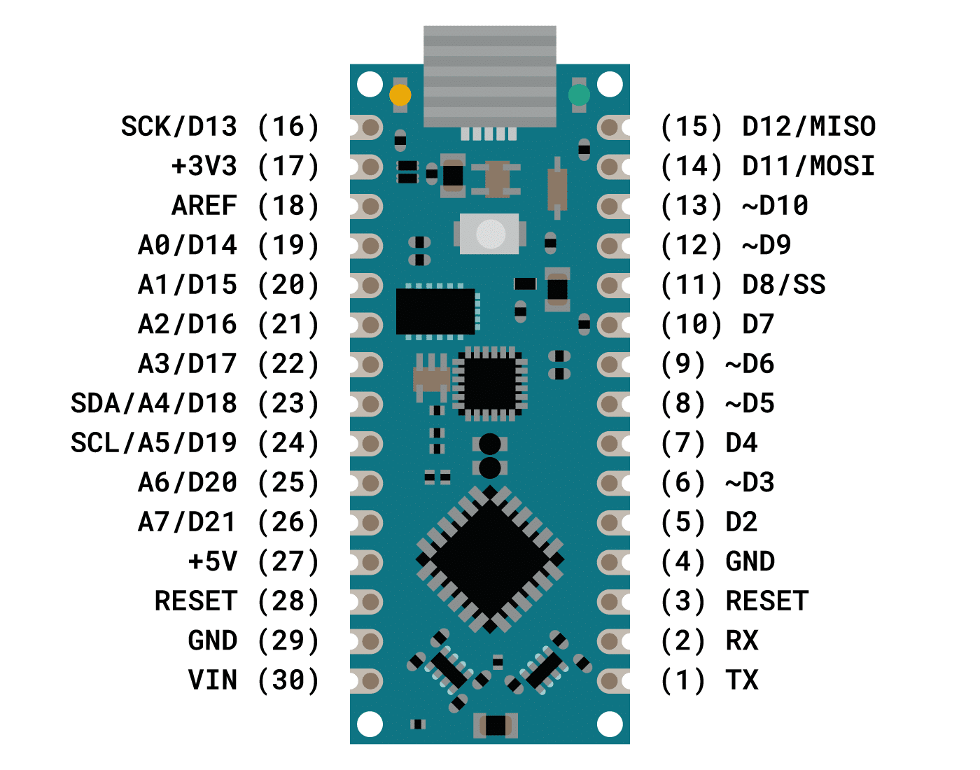
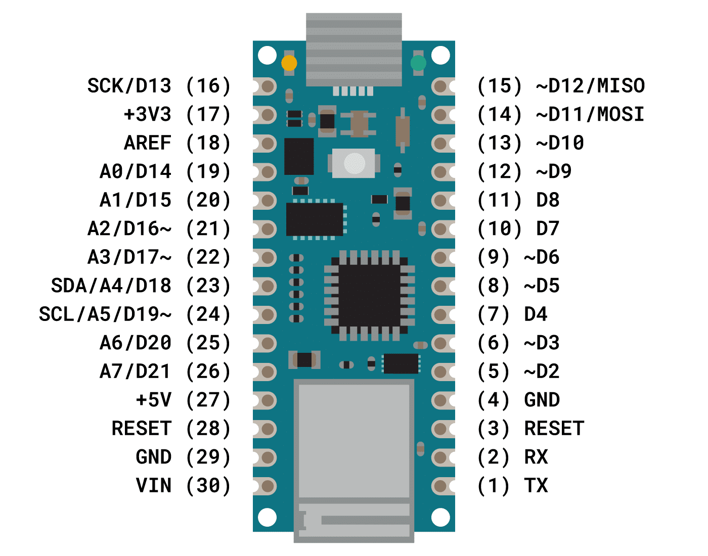
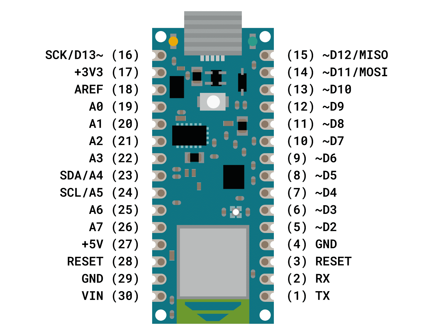
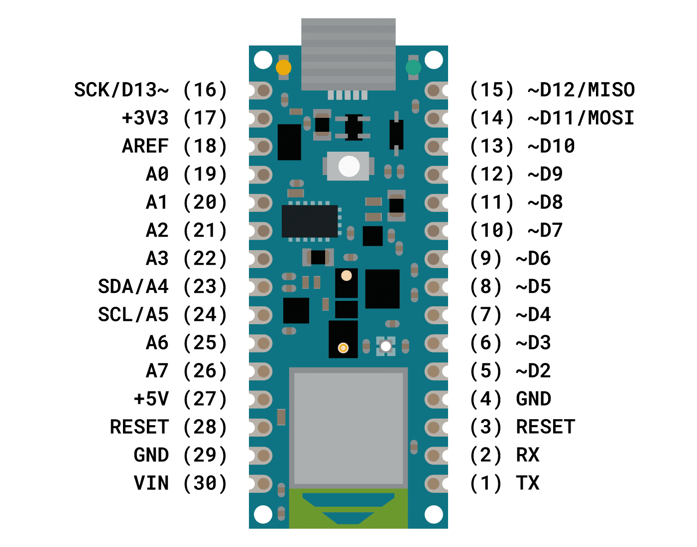
Arduino Nano pinout
The pinout of the Arduino Nano can be found in the diagram below:
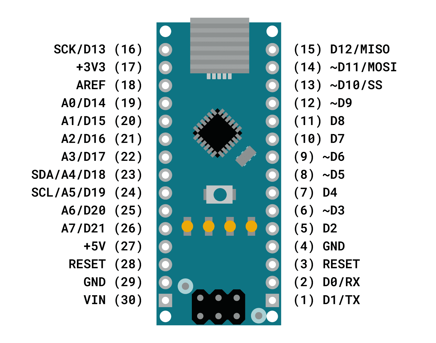
All of the digital pins of the Arduino Nano can be used as input or output, using the functions pinMode(), digitalRead(), and digitalWrite(). They operate at 5 V and each pin can receive or provide a maximum of 40 mA of current.
All the digital and analog pins also have an internal pull-up resistor (disconnected by default) of 20-50 kOhms. To use this pull-up resistor, you can use:
void setup() {
  pinMode(3, INPUT_PULLUP);
}
This can be useful when you don’t want a pin to be floating, e.g. when you connect a button to a pin.
Note that the analog pins can also be used as digital pins, using the aliases A0, A1, etc. The exception is the Arduino Nano’s A6 and A7 pins, which can only be used as analog inputs.
pinMode(A0, OUTPUT);
digitalWrite(A0, HIGH);
Some pins also have additional functions which you can find in the table below:
| Pin number | Pin name | Type | Special function |
|---|---|---|---|
| 1 | D1/TX | Digital Pin | Serial communication (TX) |
| 2 | D0/RX | Digital Pin | Serial communication (RX) |
| 3 | RESET | Other pin | Reset (active LOW) |
| 4 | GND | Ground | |
| 5 | D2 | Digital Pin | External interrupt |
| 6 | ~D3 | Digital Pin | External interrupt 8-bit PWM output |
| 7 | D4 | Digital Pin | |
| 8 | ~D5 | Digital Pin | 8-bit PWM output |
| 9 | ~D6 | Digital Pin | 8-bit PWM output |
| 10 | D7 | Digital Pin | |
| 11 | D8 | Digital Pin | |
| 12 | ~D9 | Digital Pin | 8-bit PWM output |
| 13 | ~D10 | Digital Pin | SPI communication (SS) 8-bit PWM output |
| 14 | ~D11 | Digital Pin | SPI communication (MOSI) 8-bit PWM output |
| 15 | D12 | Digital Pin | SPI communication (MISO) |
| 16 | D13 | Digital Pin | SPI communication (SCK) Connected to a built-in LED |
| 17 | +3V3 | Power | |
| 18 | AREF | Analog Pin | Reference voltage for the analog inputs |
| 19 | D14 A0 | Digital Pin Analog Pin | |
| 20 | D15 A1 | Digital Pin Analog Pin | |
| 21 | D16 A2 | Digital Pin Analog Pin | |
| 22 | D17 A3 | Digital Pin Analog Pin | |
| 23 | D18 A4 | Digital Pin Analog Pin | I2C communication (SDA) |
| 24 | D19 A5 | Digital Pin Analog Pin | I2C communication (SCL) |
| 25 | D20 A6 | Digital Pin Analog Pin | Cannot be used as a digital pin |
| 26 | D21 A7 | Digital Pin Analog Pin | Cannot be used as a digital pin |
| 27 | +5V | Power | |
| 28 | RESET | Other pin | Reset (active LOW) |
| 29 | GND | Ground | Ground |
| 30 | VIN | Power | 6 – 20 V input to the board |
Arduino Nano ICSP pins
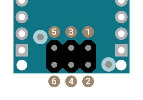
At the bottom of the Arduino Nano, you can find the ICSP (In-Circuit Serial Programming) header (6 pins). The pinout of this connector is as follows:
| Pin number | Pin Name | Type | Function |
|---|---|---|---|
| 1 | MISO | Communication | Master in slave out |
| 2 | +5V | Power | Supply voltage |
| 3 | SCK | Communication | Clock |
| 4 | MOSI | Communication | Master out slave in |
| 5 | RESET | Other pin | Reset (active LOW) |
| 6 | GND | Ground | Supply ground |
The ICSP connector can be used to program the microcontroller using Arduino ISP or similar (this bypasses the bootloader).
How to power the Arduino Nano?
The Arduino Nano can be powered in 3 ways:
- Mini-B USB connector: The most popular way to power the Arduino Nano board is with a USB cable. You can use a Mini-B USB cable connected to the USB port of your laptop, PC, or 5 V USB power adapter. This cable is also used to program the Arduino Nano.
- VIN pin: You can also power the Arduino Nano with an unregulated 6 – 20 V external power supply connected to the VIN pin (pin 30). This pin can also be used to power the microcontroller with a battery for example.
- +5V pin: It is also possible to use a 5 V external regulated power supply connected to the +5V pin (pin 27). However, this is method is not recommended because it bypasses the voltage regulators. If you want to power the board in this way, you have to make sure that the voltage level is stable and does not exceed 5 V.
If you connect multiple voltage sources, the power source is automatically selected to the highest voltage source.
Programming the Arduino Nano
The easiest way to program the Arduino Nano is with the Arduino IDE or the Arduino Web Editor. The advantage of the Arduino Web Editor is that you don’t need to install anything and your sketches are stored in the cloud.
Selecting the right board type and processor/bootloader
In the desktop Arduino IDE, you have to select the right board type, processor, and port if you want to upload sketches to the Arduino Nano.
To select the right board, go to Tools > Board > Arduino AVR Boards > Arduino Nano.
Since January 2018, Arduino Nano boards come with a new bootloader. If you have a genuine Arduino Nano that was purchased after this date, you have to select ATmega328P under Tools > Processor > ATmega328P.
If you have an older board (or an Arduino Nano compatible board/knockoff from Amazon, AliExpress, Banggood, etc.), you have to choose Tools > Processor > ATmega328P (Old Bootloader).
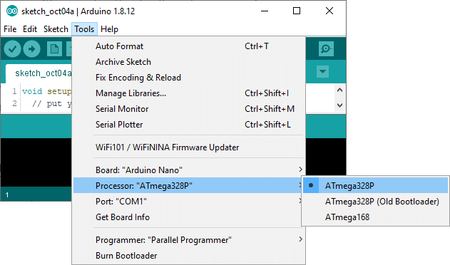
If you get an error while uploading the sketch, try changing the processor until the program compiles and uploads properly.
Lastly, select the COM port to which the Arduino Nano is connected under Tools > Port.
Communication
The Arduino Nano has several default pins that are used for communication between the Arduino board and a computer or other devices.
Serial
Digital pins D0 (RX) and D1 (TX) are used to receive (RX) and transmit (TX) TTL serial data. These pins are connected to the corresponding pins of the FTDI USB-to-TTL Serial chip.
I2C
Analog pins A4 (SDA) and A5 (SCL) support I2C (TWI) communication using the Wire library. This library can be used to communicate between the Arduino Nano and sensors, displays, other Arduino boards, etc.
In the table below, you can find the I2C pins of some of the other Arduino boards.
| Board | SDA | SCL |
|---|---|---|
| Arduino Uno | A4 | A5 |
| Arduino Nano | A4 | A5 |
| Arduino Micro | 2 | 3 |
| Arduino Mega 2560 | 20 | 21 |
| Arduino Leonardo | 2 | 3 |
| Arduino Due | 20 | 21 |
SPI
Digital pins D10 (SS), D11 (MOSI), D12 (MISO), and D13 (SCK) support SPI communication. Although SPI communication is provided by the underlying hardware, it is not currently included in the Arduino language.
Note that most of the SPI pins can also be found at the ICSP header, the only pin that is missing is the slave select pin (SS). This header is for example used by the Pixy2 camera to talk to the Arduino over SPI.
Arduino Nano LEDs
The Arduino Nano has 4 LEDs; TX LED, RX LED, Power, and LED_BUILTIN.
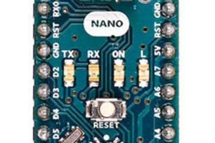
The TX and RX LEDs will flash when data is being transmitted via the FTDI chip and USB connection to the computer (but not for serial communication on pins 0 and 1).
The power LED (ON) lights up when the board is powered up.
The LED_BUILTIN (L) is connected to digital pin 13 of the board. When this pin is HIGH, the LED is on, when the pin is LOW, it’s off. You can also use the constant LED_BUILTIN in your code, e.g. when using digitalWrite(pin, value).
void setup() {
  // initialize digital pin LED_BUILTIN as an output.
  pinMode(LED_BUILTIN, OUTPUT);
}

void loop() {
  digitalWrite(LED_BUILTIN, HIGH);   // turn the LED on (HIGH is the voltage level)
  delay(1000);                       // wait for a second
  digitalWrite(LED_BUILTIN, LOW);    // turn the LED off by making the voltage LOW
  delay(1000);                       // wait for a second
}
Arduino Nano Every
The Arduino Nano Every is one of the newer, more powerful Arduino Nano boards. It uses the ATmega4809 microcontroller and is the cheapest Arduino board you can buy!
This board is also 5 V compatible and has the same form factor as the original Arduino Nano (18 x 45 mm). The small size and low cost make it ideal for wearable projects, low-cost robotics, drones, and also general use to control smaller parts of larger projects.
The key feature of the Arduino Nano Every is its new processor with more RAM and flash memory. This means that you can make larger programs with more variables than with the Arduino Uno.
If you need multiple Arduino Nano Every boards, you can also buy them in a pack at a discounted price, saving on the unit price of each board.
Arduino Nano Every specifications
| Microcontroller | ATmega4809 (datasheet) |
| Operating voltage | 5 V |
| Input voltage (VIN) | 7-21 V |
| DC current per I/O pin | 40 mA (20 mA recommended) |
| DC current for 3.3 V pin | 50 mA |
| CPU flash memory | 48 KB (ATMega4809) |
| SRAM | 6 KB (ATMega4809) |
| Clock speed | 20 MHz |
| EEPROM | 256 byte (ATMega4809) |
| PWM pins | 5 (D3, D5, D6, D9, D10) |
| UART | 1 |
| SPI | 1 |
| I2C | 1 |
| Analog input pins | 8 (ADC 10 bit) |
| Analog output pins | Only through PWM (no DAC) |
| External interrupts | All digital pins |
| LED_BUILTIN | D13 |
| USB | ATSAMD11D14A |
| PCB size | 18 x 45 mm |
| Weight | 5 g (with headers) |
| Cost | Check price |
You can download the schematics for this board below:
The Fritzing model of the Arduino Nano Every can be found here:
Arduino Nano Every pinout
The pinout of the Arduino Nano Every can be found in the diagram below. Note that the Arduino Nano Every is almost 100% pin-compatible with the original Arduino Nano and it also runs on 5 V. The important differences are:
- This board doesn’t have PWM on D11 and therefore it supports only 5 PWM outputs instead of 6.
- SPI SS is on pin D8 instead of D10.
- External interrupts are allowed on all pins, not just pin D2 and D3.
- Analog pins A6 and A7 can also be used as digital pins.
The green LED on the board (right) is the power LED and the orange LED (left) is LED_BUILTIN.
Programming the Arduino Nano Every
If you want to use the desktop Arduino IDE to program the Arduino Nano Every, you have to follow a couple of steps before you can upload sketches to the board.
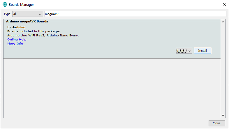
Install megaAVR core and drivers
First, you need to add the Arduino MegaAVR core to the Arduino IDE. To do this go to Tools > Board > Boards Manager. Now search for ‘megaAVR’ and select Arduino megaAVR Boards by Arduino. Select the latest version and click Install.
After you have installed the megaAVR core, the drivers will install automatically once you connect the Arduino Nano Every to your computer with a USB cable.
Select the right board and port
Now select Arduino Nano Every under Tools > Board > Arduino megaAVR Boards.
Next, select the right COM port under the Tools > Port menu. If you disconnect and reconnect your board while looking at the menu, you should be able to see which entry is the Arduino board.
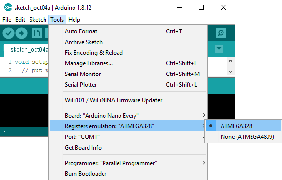
Compilation errors? Try “Register emulation”
Although the Arduino Nano Every is fully electrically compatible with the original Arduino Nano (it also works at 5 V), you might run into issues if your (old) code uses third-party libraries that don’t manage the pin mapping of the microcontroller.
If you have compilation errors you can try to turn on the “Register emulation” mode to emulate ATmega328P registers in the ATmega4809 while compiling.
Arduino Nano 33 IoT
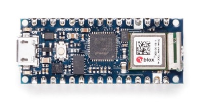
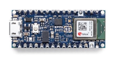
The Arduino Nano 33 IoT is one of the 3.3 V variants of the Arduino Nano family. It features an Arm Cortex-M0+ microcontroller, pre-certified ESP32-based WiFi and Bluetooth module from u-blox, and an onboard ECC608A crypto chip which provides IoT security. The board also features an LSM6DS3 6-axis IMU.
The Nano 33 IoT is essentially an MKR WiFi 1010, but it sacrifices a battery charger and shield compatibility in favor of a smaller footprint and lower cost. It costs even less than the original Arduino Nano!
Arduino Nano 33 IoT specifications
| Microcontroller | SAMD21 Cortex®-M0+ 32bit low power ARM MCU |
| Radio module | u-blox NINA-W102 |
| Secure element | ATECC608A |
| Operating voltage | 3.3 V |
| Input voltage (VIN) | 5-21 V |
| DC current per I/O pin | 7 mA |
| CPU flash memory | 256 KB |
| SRAM | 32 KB |
| Clock speed | 48 MHz |
| EEPROM | None |
| Digital I/O pins | 14 |
| PWM pins | 11 (2, 3, 5, 6, 9, 10, 11, 12, 16 / A2, 17 / A3, 19 / A5) |
| UART | 1 |
| SPI | 1 |
| I2C | 1 |
| Analog input pins | 8 (ADC 8/10/12 bit) |
| Analog output pins | 1 (DAC 10 bit) |
| External interrupts | All digital pins (all analog pins can also be used as interrupt pins, but will have duplicated interrupt numbers) |
| LED_BUILTIN | D13 |
| USB | Native in the SAMD21 processor |
| Inertial measurement unit (IMU) | LSM6DS3 (6-axis) |
| PCB size | 18 x 45 mm |
| Weight | 5 g (with headers) |
| Cost | Check price |
The Arduino Nano 33 IoT is open-source hardware! You can download the schematics for this board below:
The Fritzing model of the Arduino Nano 33 IoT can be found here:
Arduino Nano 33 IoT pinout
The pinout of the Nano 33 IoT is almost exactly the same as the original Nano board (see diagram below).
A couple of important things to remember are:
- The Arduino Nano 33 IoT only supports 3.3 V for the GPIO pins, so it is not 5 V tolerant like most of the other Arduino boards. Connecting more than 3.3 V to the GPIO pins will damage the board!
- The +5V pin on the board is not connected by default. If you want to use this pin, you have to short the VBUS jumper on the back of the board. Note that this pin only outputs 5 V from the board when powered from the USB connector. If you power the board from the VIN pin, you won’t get any regulated 5 V, even if you do the solder bridge.
- As opposed to other Arduino Nano boards, pins A4 and A5 have an internal pull-up and default to be used as an I2C bus. So, usage as analog inputs is not recommended.
Programming the Arduino Nano 33 IoT on the Arduino IDE
If you want to program this board with the Arduino desktop IDE, you need to add the Arduino SAMD Core to it. To do this go to Tools > Board > Boards Manager. Now search for ‘SAMD’ and select Arduino SAMD Boards (32-bits ARM Cortex-M0+) by Arduino. Select the latest version and click Install.
If you properly installed the SAMD Core, Windows should initiate its driver installation process automatically once you connect the board to your computer with a micro USB cable.
Before you can upload your program to the board, select Arduino NANO 33 IoT under Tools > Board > Arduino SAMD (32-bits ARM Cortex-M0+) Boards.
Next, select the right COM port under the Tools > Port menu. If you disconnect and reconnect your board while looking at the menu, you should be able to see which entry is the Arduino board.
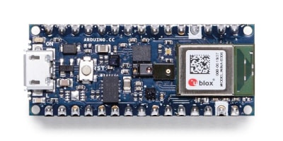
Arduino Nano 33 BLE
The Arduino Nano 33 BLE is based on the powerful Nordic nRF52840 microcontroller with advanced Bluetooth capabilities. The board features a u-blox NINA B306 module and also includes a 9-axis inertial measurement unit (IMU). The IMU is an LSM9DS1, which is a 3-axis accelerometer, 3-axis gyroscope, and 3-axis magnetometer. You can use the example sketches in the ArduinoLSM9DS1 library to use the sensor.
The main processor is a lot more powerful than the one from the standard Arduino Nano (it has 1 MB of program memory and 256 KB of RAM) and runs at a much higher clock speed. It also includes other amazing features like Bluetooth pairing via NFC and ultra low power consumption modes.
Arduino Nano 33 BLE specifications
| Microcontroller | nRF52840 |
| Operating voltage | 3.3 V |
| Input voltage (VIN) | 5-21 V |
| DC current per I/O pin | 15 mA |
| CPU flash memory | 1 MB (nRF52840) |
| SRAM | 256 KB (nRF52840) |
| Clock speed | 64 MHz |
| EEPROM | None |
| Digital I/O pins | 14 |
| PWM pins | All digital pins |
| UART | 1 |
| SPI | 1 |
| I2C | 1 |
| Analog input pins | 8 (ADC 12 bit 200 k samples) |
| Analog output pins | Only through PWM (no DAC) |
| External interrupts | All digital pins |
| LED_BUILTIN | D13 |
| USB | Native in the nRF52840 processor |
| Inertial measurement unit (IMU) | LSM9DS1 (9-axis) |
| PCB size | 18 x 45 mm |
| Weight | 5 g (with headers) |
| Cost | Check price |
The Arduino Nano 33 BLE is open-source hardware! You can download the schematics for this board below:
The Fritzing model of the Arduino Nano 33 BLE can be found here:
Arduino Nano 33 BLE pinout
Just like the Arduino Nano 33 IoT, you need to short the VBUS jumper on the back of the board if you want to use the +5V output.
You can connect an external NFC antenna between pins D7 and D8 to activate Bluetooth pairing of the board over NFC.
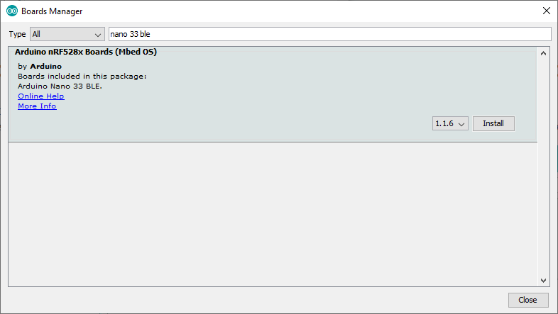
Programming the Arduino Nano 33 BLE/Sense with the Arduino IDE
If you want to use the Arduino Nano 33 BLE or BLE Sense with the Arduino Desktop IDE, you need to add the Arduino nRF528x mbed Core to it. To do this go to Tools > Board > Boards Manager. Now search for ‘nano 33 ble’ and select Arduino nRF528x Boards (Mbed OS) by Arduino. Select the latest version and click Install.
If you properly installed the nRF528x Core, Windows should initiate its driver installation process automatically once you connect the board to your computer with a micro USB cable.
Before you can upload your program to the board, select Arduino NANO 33 BLE under Tools > Board > Arduino nRF528x Boards (Mbed OS).
Next, select the right COM port under the Tools > Port menu. If you disconnect and reconnect your board while looking at the menu, you should be able to see which entry is the Arduino board.
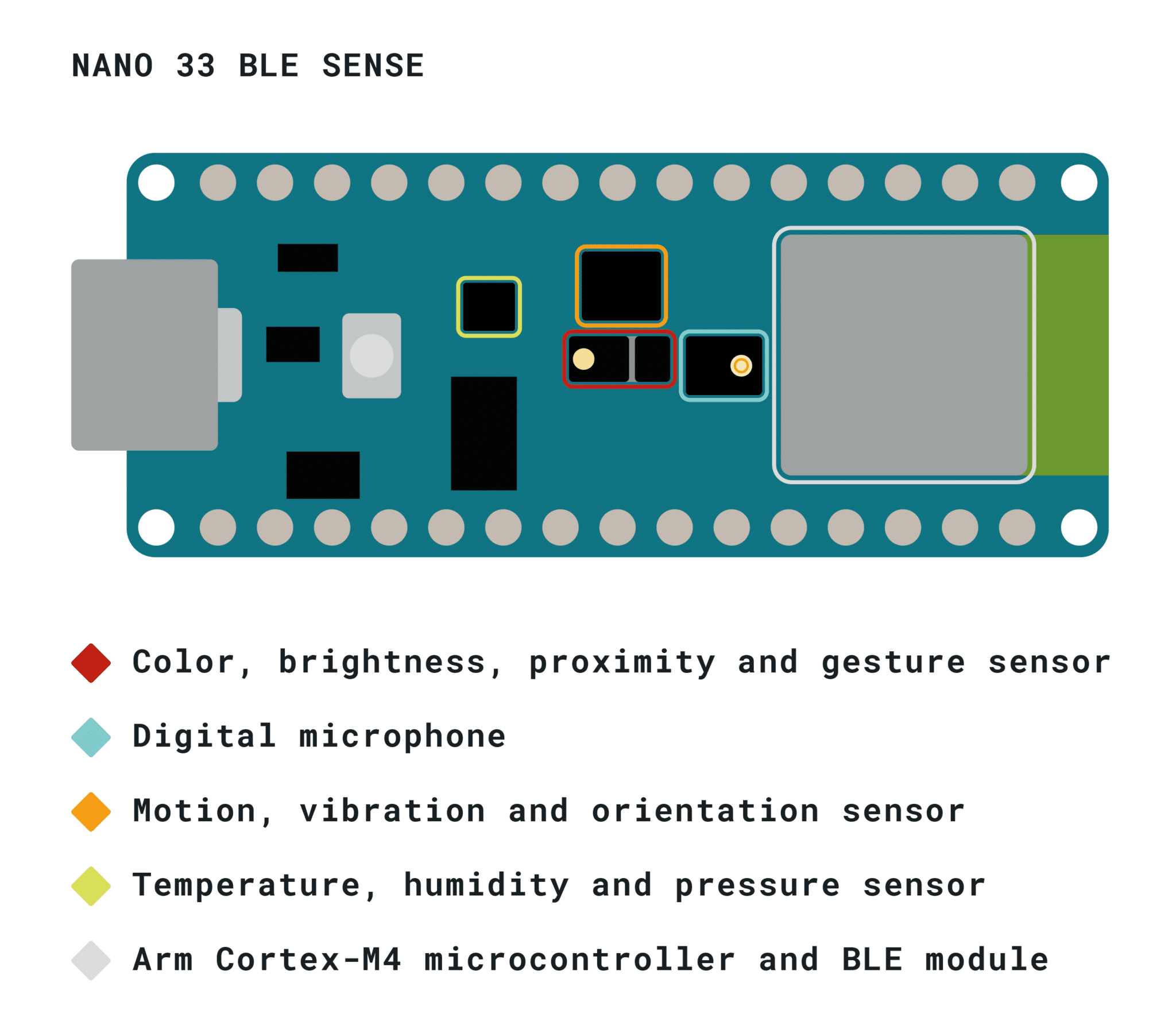
Arduino Nano 33 BLE Sense
The Arduino Nano 33 BLE Sense features the same 32-bit ARM Cortex-M4 processor as the Arduino Nano 33 BLE, but also includes a bunch of onboard sensors: a 9-axis IMU, temperature, pressure, humidity, light, color, gesture sensors, and even a microphone that are managed through several specialized Arduino libraries.
This board has become very popular as a machine learning platform using TensorFlow Lite for microcontrollers (TinyML). You can find a detailed getting started guide on the Arduino site and some great examples on twitter.
Arduino Nano 33 BLE Sense specifications
| Microcontroller | nRF52840 |
| Operating voltage | 3.3 V |
| Input voltage (VIN) | 5-21 V |
| DC current per I/O pin | 15 mA |
| CPU flash memory | 1 MB (nRF52840) |
| SRAM | 256 KB (nRF52840) |
| Clock speed | 64 MHz |
| EEPROM | None |
| Digital I/O pins | 14 |
| PWM pins | All digital pins |
| UART | 1 |
| SPI | 1 |
| I2C | 1 |
| Analog input pins | 8 (ADC 12 bit 200 k samples) |
| Analog output pins | Only through PWM (no DAC) |
| External interrupts | All digital pins |
| LED_BUILTIN | D13 |
| USB | Native in the nRF52840 processor |
| Inertial measurement unit (IMU) | LSM9DS1 (9-axis) |
| Microphone | MP34DT05 |
| Gesture, light, proximity | APDS9960 |
| Barometric pressure | LPS22HB |
| Temperature, humidity | HTS221 |
| PCB size | 18 x 45 mm |
| Weight | 5 g (with headers) |
| Cost | Check price |
The Arduino Nano 33 BLE Sense is open-source hardware! You can download the schematics for this board below:
The Fritzing model of the Arduino Nano 33 BLE Sense can be found here:
Arduino Nano 33 BLE Sense Pinout
Programming the Arduino Nano 33 BLE Sense with the Arduino IDE
You can use the same procedure as for the Arduino Nano 33 BLE to install the Arduino nRF528x mbed Core (see above). Because the Arduino Nano 33 BLE Sense is a hardware variation of the Arduino Nano 33 BLE, both boards are recognized as the Arduino nano 33 BLE and this is normal. In the board manager and the board selection, you will only find Arduino Nano 33 BLE.
Arduino Nano comparison
Are you wondering which Arduino Nano board would work best for your project? Check out the table below for a comparison.
Arduino Nano comparison table
| Property | Arduino Nano | Arduino Nano Every | Arduino Nano 33 IoT | Arduino Nano 33 BLE | Arduino Nano 33 BLE Sense |
|---|---|---|---|---|---|
| Microcontroller | ATmega328 | ATMega4809 | SAMD21 Cortex®-M0+ 32bit low power ARM MCU | nRF52840 | nRF52840 |
| Operating voltage | 5 V | 5 V | 3.3 V | 3.3 V | 3.3 V |
| Input voltage (VIN) | 6-20 V | 7-21 V | 5-21 V | 5-21 V | 5-21 V |
| Clock speed | 16 Mhz | 20 MHz | 48 MHz | 64 MHz | 64 MHz |
| Flash | 32 KB | 48 KB | 256 KB | 1 MB | 1 MB |
| RAM | 2 KB | 6 KB | 32 KB | 256 KB | 256 KB |
| Current per pin | 40 mA | 40 mA | 7 mA | 15 mA | 15 mA |
| PWM pins | 6 | 5 | 11 | All | All |
| IMU | No | No | LSM6DS3 (6-axis) | LSM9DS1 (9-axis) | LSM9DS1 (9-axis) |
| Other sensors | No | No | No | No | Microphone, gesture, light, proximity, barometric pressure, temperature, humidity |
| WiFi | No | No | Yes | No | No |
| Bluetooth | No | No | Yes | Yes | Yes |
| USB type | Mini | Micro | Micro | Micro | Micro |
| Price* | $20 Amazon | $12.50 Amazon | $20 Amazon | $23 Amazon | $33 Amazon |
Makerguides.com is a participant in the Amazon Services LLC Associates Program, an affiliate advertising program designed to provide a means for sites to earn advertising fees by advertising and linking to products on Amazon.com. As an Amazon Associate we earn from qualifying purchases.
*Prices can vary depending on your region and distributor.
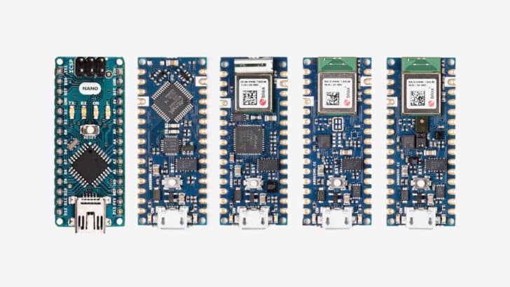
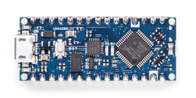
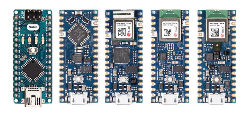
Form factor
Besides the differences mentioned in the table above, there is one more important difference between the original and the newer Arduino Nano boards and that is the form factor.
The original Arduino Nano has components mounted on both the top and the bottom of the board, whereas the newer Arduino Nano boards only have components mounted on the top.
Another difference is that you can get the board with or without soldered headers. The boards without soldered headers do include them in the box so you can still install the headers yourself. Note that the board without pre-soldered headers is also a bit cheaper.
Lastly, besides the standard through holes, the board also comes with castellated connectors.
All these features combined allow you to solder the board directly onto your own design, minimizing the height of your whole prototype.
The outside and hole dimensions are the same for all of the boards.
Conclusion
With their small form factor and low cost, the Arduino Nano boards are a great choice for many electronics projects. The newer boards add several awesome features to the original Arduino Nano, like WiFi and Bluetooth connectivity, an IMU, and several other onboard sensors.
If you want an onboard battery charge controller or more pins, check out the MKR family of boards and the Arduino Mega.
If you have any questions, suggestions, or think that things are missing in this article, please leave a comment below.
Note that comments are held for moderation to prevent spam.

This work is licensed under a Creative Commons Attribution-NonCommercial-ShareAlike 4.0 International License.
Other Useful Links From Around The Web:
Benne is professional Systems Engineer with a deep expertise in Arduino and a passion for DIY projects.
Dave A
Monday 4th of December 2023
One important thing left out is the adc reference voltage, is it 3.3 or 5v. Can higher ext voltages be used.
Stefan Maetschke
Monday 4th of December 2023
AREF cannot be higher than 5V. For the nano boards the default reference seems to be 3.3V but I haven't verified this https://www.arduino.cc/reference/en/language/functions/analog-io/analogreference/
Nate Ocean
Friday 3rd of June 2022
Arduino Nano ICSP pins diagram is wrong. It is rotated 180-degree. Correctly, the #1 pin is on the outside edge of the board.