Measuring carbon dioxide (CO2) in the air can be very useful in monitoring indoor air quality, as well as levels of pollution in the atmosphere.
CO2 is produced indoors when people breathe, and in an enclosed space the levels can often rise above 1000ppm and make you feel drowsy, sleepy or even lead to headaches.
You can use a CO2 sensor to monitor the carbon dioxide in the air, and provide warning signals that can help you to improve air quality.
You can also utilise CO2 sensors in horticultural applications and they can be very useful to create the correct growing conditions in mushroom cultivation.
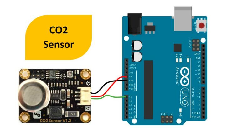
In this article, we will use a CO2 sensor from DFrobot to monitor the ambient CO2 levels.
You also have the option to trigger an alarm using a digital pin available on the CO2 sensor.
We will understand the basics of the CO2 sensor (MG-811) and its features.
In the later section, we will cover the connection diagrams followed by the required Arduino code.
At the end of the article, you will find a collection of the most frequently asked questions on the DFrobot CO2 sensors with answers.
Let’s get started!
Components Needed To Build Arduino And CO2 Sensor Project
Hardware Components
- Dupont wire x 1 set
- Arduino USB cable (for powering Arduino and programming) x 1
Software
Makerguides.com is a participant in the Amazon Services LLC Associates Program, an affiliate advertising program designed to provide a means for sites to earn advertising fees by advertising and linking to products on Amazon.com.
Basics of The CO2 Sensor Based On MG-811
In this section, we will understand the features, specifications, and connection options available on the CO2 sensor.
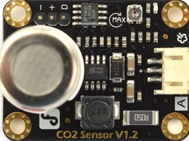
The top view of the CO2 sensor is presented below.
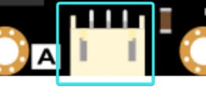
Connector details of the CO2 sensor
The sensor has two connection options. The main connector has an analog output.
The analog output is proportional to the CO2 concentration levels.
The table below has the information on the pin details.
| Pin Name | Pin Description | Remarks |
| A | Analog Output | Analog Output proportional to the CO2 sensor. |
| + | Power supply – 5 V | You can use onboard 5 V to power the sensor |
| – | Ground | Common ground connections |
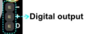
You also have an alternate option to simply detect whether the Co2 levels are above the preset limit.
In this case, you can use an Arduino GPIO pin to make the connections.
The table below summarises the digital output connector pin details.
| Pin Name | Pin Description | Remarks |
| – | Analog Output | Common ground connection |
| + | Power supply – 5 V | You can use onboard 5 V to power the sensor |
| D | Digital Output | You can use the digital output pin |
Features of the Arduino CO2 sensor
The features of the CO2 sensor are listed here.
- Signal conditioning circuit to amplify the sensor’s analog voltage
- Onboard heating circuit to bring the sensor into best operation mode
- MG-811-based sensor with all parts meeting industrial quality standard
Specifications of the Arduino CO2 sensor
The CO2 sensor’s specifications are listed below.
- Operating voltage is 5 V
- Analog Output – Compatible with Arduino analog input pin
- One Digital output option
- Onboard heating circuit
- Electrochemical sensor
Step-By-Step Instructions To Connect The CO2 Sensor With Arduino UNO
In this section, we will build a project using Arduino UNO and the Carbon dioxide sensor.
The connections are easy to take significantly less time to complete.
Three pins on the CO2 sensor are available to connect to the Arduino UNO.
Let’s get started with the hardware connections!
How To Connect The DFrobot CO2 Sensor To The Arduino UNO?
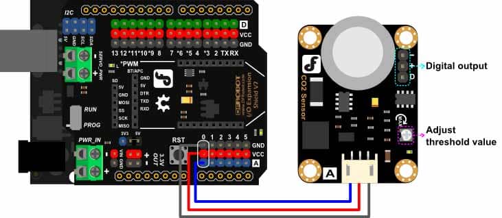
Below is the step-by-step guide to complete the minimal connections needed to connect the Arduino and CO2 Sensor.
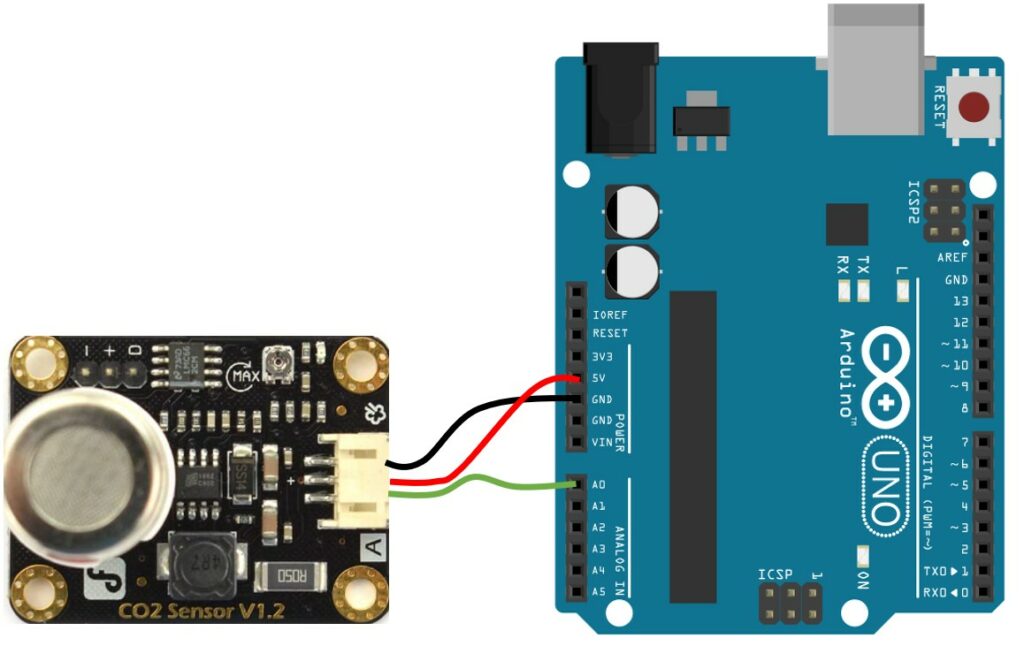
Step 1: Start with the GND connections.
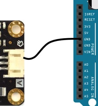
You can connect any GND pins available on the Arduino UNO board.
The ground pin on the sensor is the first pin from the top in the image.
Always start with the ground connections.
Connecting the GND pins first avoids accidental damage to the boards.
Step 2: Connect the Analog Output
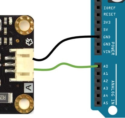
Connect the Analog Output of the sensor to the A0 pin of the Arduino UNO. You can choose to use any of the analog pins available.
Please ensure the analog pin used for the connection is the same as the one used in the Arduino UNO code.
Arduino Board has six analog inputs. You can connect up to six CO2 sensors in parallel.
Step 3: Complete the power connections
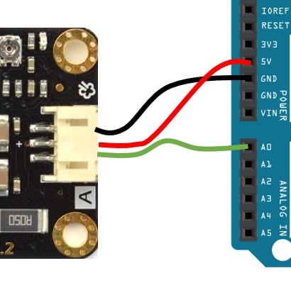
Connect the 5 V pin of the Arduino UNO to the Supply pin of the CO2 sensor.
Congratulations, you have completed all the necessary connections needed.
Step 4: Verify the complete connection
In the next sections, we will walk through the Arduino code required to test the connections!
Arduino Code Example For The Arduino and CO2 Sensor Project
In this section, we will walk through the example Arduino code to verify the CO2 sensor module.
The complete Arduino code for the CO2 sensor
/*******************Demo for MG-811 Gas Sensor Module V1.1*****************************
Author:  Tiequan Shao: [email protected]
         Peng Wei:     [email protected]

Lisence: Attribution-NonCommercial-ShareAlike 3.0 Unported (CC BY-NC-SA 3.0)

Note:    This piece of source code is supposed to be used as a demostration ONLY. More
         sophisticated calibration is required for industrial field application.

                                                    Sandbox Electronics    2012-05-31
************************************************************************************/

/************************Hardware Related Macros************************************/
#define         MG_PIN                       (A0)     //define which analog input channel you are going to use
#define         BOOL_PIN                     (2)
#define         DC_GAIN                      (8.5)   //define the DC gain of amplifier

/***********************Software Related Macros************************************/
#define         READ_SAMPLE_INTERVAL         (50)    //define how many samples you are going to take in normal operation
#define         READ_SAMPLE_TIMES            (5)     //define the time interval(in milisecond) between each samples in
                                                     //normal operation

/**********************Application Related Macros**********************************/
//These two values differ from sensor to sensor. user should derermine this value.
#define         ZERO_POINT_VOLTAGE           (0.220) //define the output of the sensor in volts when the concentration of CO2 is 400PPM
#define         REACTION_VOLTGAE             (0.030) //define the voltage drop of the sensor when move the sensor from air into 1000ppm CO2

/*****************************Globals***********************************************/
float           CO2Curve[3]  =  {2.602,ZERO_POINT_VOLTAGE,(REACTION_VOLTGAE/(2.602-3))};
                                                     //two points are taken from the curve.
                                                     //with these two points, a line is formed which is
                                                     //"approximately equivalent" to the original curve.
                                                     //data format:{ x, y, slope}; point1: (lg400, 0.324), point2: (lg4000, 0.280)
                                                     //slope = ( reaction voltage ) / (log400 –log1000)

void setup()
{
    Serial.begin(9600);                              //UART setup, baudrate = 9600bps
    pinMode(BOOL_PIN, INPUT);                        //set pin to input
    digitalWrite(BOOL_PIN, HIGH);                    //turn on pullup resistors

   Serial.print("MG-811 Demostration\n");
}

void loop()
{
    int percentage;
    float volts;

    volts = MGRead(MG_PIN);
    Serial.print( "SEN0159:" );
    Serial.print(volts);
    Serial.print( "V           " );

    percentage = MGGetPercentage(volts,CO2Curve);
    Serial.print("CO2:");
    if (percentage == -1) {
        Serial.print( "<400" );
    } else {
        Serial.print(percentage);
    }

    Serial.print( "ppm" );
    Serial.print("\n");

    if (digitalRead(BOOL_PIN) ){
        Serial.print( "=====BOOL is HIGH======" );
    } else {
        Serial.print( "=====BOOL is LOW======" );
    }

    Serial.print("\n");

    delay(500);
}

/*****************************  MGRead *********************************************
Input:   mg_pin - analog channel
Output:  output of SEN-000007
Remarks: This function reads the output of SEN-000007
************************************************************************************/
float MGRead(int mg_pin)
{
    int i;
    float v=0;

    for (i=0;i<READ_SAMPLE_TIMES;i++) {
        v += analogRead(mg_pin);
        delay(READ_SAMPLE_INTERVAL);
    }
    v = (v/READ_SAMPLE_TIMES) *5/1024 ;
    return v;
}

/*****************************  MQGetPercentage **********************************
Input:   volts   - SEN-000007 output measured in volts
         pcurve  - pointer to the curve of the target gas
Output:  ppm of the target gas
Remarks: By using the slope and a point of the line. The x(logarithmic value of ppm)
         of the line could be derived if y(MG-811 output) is provided. As it is a
         logarithmic coordinate, power of 10 is used to convert the result to non-logarithmic
         value.
************************************************************************************/
int  MGGetPercentage(float volts, float *pcurve)
{
   if ((volts/DC_GAIN )>=ZERO_POINT_VOLTAGE) {
      return -1;
   } else {
      return pow(10, ((volts/DC_GAIN)-pcurve[1])/pcurve[2]+pcurve[0]);
   }
}
You have to mention the analog pin planned to use for the connections here. In our case, it is pin A0.
#define MG_PIN (A0) //define which analog input channel you are going to use
You can find the steps to calibrate the sensor in the FAQ section below.
Update the lin below with the value you came up with to complete the calibration.
#define ZERO_POINT_VOLTAGE (0.220) //define the output of the sensor in volts when the concentration of CO2 is 400PPM
FAQs About The CO2 Sensor And Arduino Projects
I have included a list of the most frequently asked questions about projects built using Arduino and the CO2 sensor.
If you have more questions, please post them in the comments section.
I will be glad to answer them.
1. How do you calibrate the CO2 sensor?
The CO2 sensor is an electrochemical sensor that you can calibrate easily. It would help if you calibrated the sensor before you read the measurements.
There is a parameter called ‘ZERO_POINT_VOLTAGE.’
You have to measure the zero-point voltage for your board and update the line below in the Arduino sketch.
#define ZERO_POINT_VOLTAGE (0.220) //define the output of the sensor in volts when the concentration of CO2 is 400PPM
To find the zero-point voltage, please follow the steps below.
- Place the sensor in a clean-air environment
- Power on and leave the board for 48 hours
- Measure the output voltage on the analog output pin
- Divide the output voltage measured by 8.5
- If the measured voltage is 2.4 V, the zero point voltage will be 0.282 V
2. Which CO2 sensor is the best?
The CO2 sensor discussed in the article is a good option for most applications. To evaluate the best sensor, you should first list the requirements.
There is no single sensor that suits all the applications.
Some sensors have longer calibration times, some won’t work at 3.3 V, and others need precise external references.
Sensors prices will also vary significantly based on the features and the operating environment they are expected to function.
3. What are the units in which CO2 is specified?
The CO2 levels in the atmosphere are very low. The oxygen, for example, is about 21%.
Nitrogen is about 78%. The CO2 is about 0.03% to 0.04%.
Hence, usually, CO2 gas is species in PPM.
A 0.04% concentration is referred to as 400 PPM. PPM stands for parts per million.
4. Which sensor should I choose for the Indoor Air Quality application?
The CO2 sensors, whose specifications are between 2000 PPM and 10000 PPM, are better suited for indoor air quality monitoring in closed areas such as party halls, schools, and offices.
The sensors used will have a good resolution. The typical open-air CO2 concentration is about 440 PPM.
5. What are the applications of the CO2 sensors?
The CO2 sensors are employed in a variety of applications:
- Indoor Air Quality monitoring – The amount of CO2 in a room is a good indication of how well the room is air-conditioned. Higher levels of CO2 indicate poor air quality. You can find CO2 sensors used in schools and hospitals to monitor and regulate CO2 concentration.
- Air Quality Monitoring in Parking spaces is generally in the basements. Due to poor air circulation and high contraction of vehicle emissions, CO2 can rise to dangerous levels. You will find the CO2 sensors used in parking lots to support the working staff and general public by monitoring the CO2 levels.
- CO2 Fire suppression systems – You need to ensure a higher level of CO2 in specific areas to avoid the possibility of fire incidents
- Farming (Example: Mushroom culture) – Regulating the amount of CO2, optimizes the yield. Hence you can find several applications of Co2 in farming.
Conclusion
In this article, we covered the basics of the CO2 sensor from DFRobot, which is abed on the MG-811 gas sensor.
We covered the connection details, calibration mechanisms, and the example Arduino code to test the connections.
I have used CO2 sensors in my project where I monitor the living room air quality and display it using LED color indication.
The CO2 sensor is easy to use and fun to build projects around.
By monitoring the CO2 levels and regulating them, we can improve air quality for ourselves and the people around us.
If you have any feedback to improve the article, please share them in the comments section.
Your valuable input helps me to improve the article quality and bring more helpful content in the future.
Please remember to share the article with your fellow Arduino enthusiasts.

I am Puneeth. I love tinkering with open-source projects, Arduino, ESP32, Pi and more. I have worked with many different Arduino boards and currently I am exploring, Arduino powered LoRa, Power line communication and IoT.
Gino
Wednesday 6th of September 2023
Hi, I wpold like to measure co2 levels in a chimney, would this be possible with arduino. Thank You in advance Regards Gino
Stefan Maetschke
Thursday 7th of September 2023
In theory this should be possible. But you will need to make sure that the sensor doesn't get too hot and has a range suitable for the co2 levels in a chimney. I never tried that, however, and I am not familiar with suitable sensors for this application.