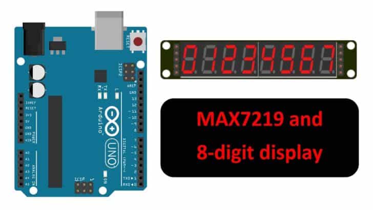
Are you looking for a way to drive a 7-segment display easily? I’ve got just the right solution for you – the MAX7219 IC.
What is MAX7219? It’s a common-cathode display driver that interfaces microprocessors to 7-segment numeric LED displays of up to 8 digits, bar-graph displays, or 64 individual LEDs.
Additionally, it helps you save pins on your MCU. The pins of MCU are scarce. The best part is it’s super easy to control with a simple serial interface.
In this article, I will tell you all about the IC’s features and specifications, voltage, current consumption, etc.
I have also covered a step-by-step guide to complete the connections between the MAX7219 7-segment display board and Arduino UNO.
You can create multiple applications with the MAX7219 IC, like digital clocks, electronic scoreboards, and more.
So, grab your breadboard, and let’s get started!
Components Needed To Build Arduino And MAX7219 7-segment Display Project
Hardware Components
- Dupont wire x 1 set
- Breadboard x 1 set
- Arduino USB cable (for powering Arduino and programming) x 1
Software
Makerguides.com is a participant in the Amazon Services LLC Associates Program, an affiliate advertising program designed to provide a means for sites to earn advertising fees by advertising and linking to products on Amazon.com. As an Amazon Associate we earn from qualifying purchases.
Basics Of MAX7219 Module
The MAX7219 is an integrated circuit that is used to drive arrays of up to 8×8 LED matrices or 7-segment displays.
It can be controlled through a simple serial interface and provides a convenient way to interface microcontrollers or microprocessors with LED displays.
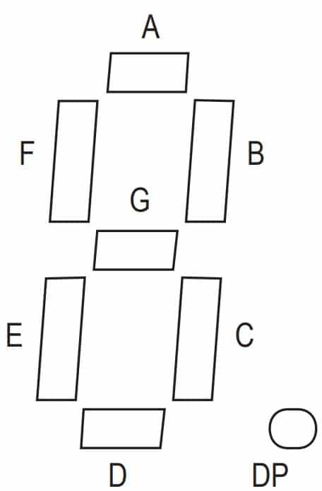
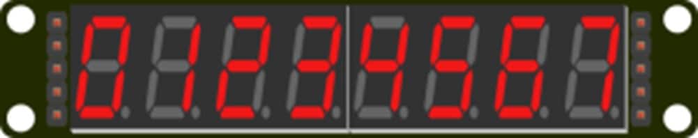
A basic 7-segment arrangement is shown below.
The MAX7219 simplifies the process of controlling many LEDs.
It provides a single-chip solution that can be programmed to control multiple displays and also provides features such as display intensity control and digit scanning.
The MAX7219 offers a low-power shutdown mode consuming only 150 µA, analog and digital brightness control, a scan-limit register to display 1 to 8 digits, and a test mode to light up all LEDs.
Hence, it is a go-to solution for low-power applications.
Key Features of MAX7219 IC
- Control 8-digit LED displays
- Energy-efficient low-power shutdown mode
- Adjust brightness through analog or digital means
- Display 1 to 8 digits through the scan-limit register
- Force all LEDs on through test mode
- Display blank on Power up (no junk display until MCU is ready)
- Convenient 20-pin DIP package
Specifications of MAX7219 IC
- Operating voltage: 4.0 – 5.5 V
- Individual LED Segment Control
- Supports Digital and Analog brightness control
- Operating temperature range: -40 °C to 85 °C
- Maximum output current per segment: 25 mA
- Serial input data rate: 10 MHz
- Display blanked on power-up
- Shutdown supply current: 150 uA (data retained)
Applications of MAX7219 IC
- Digital clocks and timers – The MAX7219 can be used to drive LED displays for showing the time and counting down intervals in a compact and energy-efficient manner.
- LED matrix displays for gaming and other interactive applications – The MAX7219 can drive individual LEDs in a matrix configuration, making it ideal for creating dynamic LED displays in games and other interactive applications.
- Industrial control panels and gauges – The MAX7219 can be used to create displays for monitoring and displaying real-time data in industrial control panels and gauges.
- Point-of-sale systems – The MAX7219 can be used to create displays for showing prices and product information in point-of-sale systems.
- LED message boards – The MAX7219 can be used to drive LED displays for displaying messages and other information in public spaces.
- Elevator floor displays – The MAX7219 can be used to drive LED displays for showing the floor number in elevators.
- Traffic signal displays – The MAX7219 can be used to drive LED displays for showing traffic signals in a compact and energy-efficient manner.
- Digital thermometers and temperature displays – You can use the MAX7219 to drive LED displays showing temperature readings in digital thermometers and temperature displays. It is a helpful addition to gates where people are screened for fever.
- Process control displays – The MAX7219 can help you create displays for monitoring and displaying real-time data in process control systems.
- Coin-operated vending machines and arcade games – The MAX7219 can be used to create LED displays for showing information and displaying game results in coin-operated vending machines and arcade games.
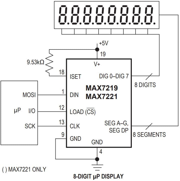
Here is the functional block diagram of a system in which MAX7219 is driving a 7-segment display:
The MCU communicates with the MAX7219 chip over SPI (Serial Peripheral Interface).
Pin Details of The MAX7219 IC
The MAX7219 comes in 24 pin DIP package.
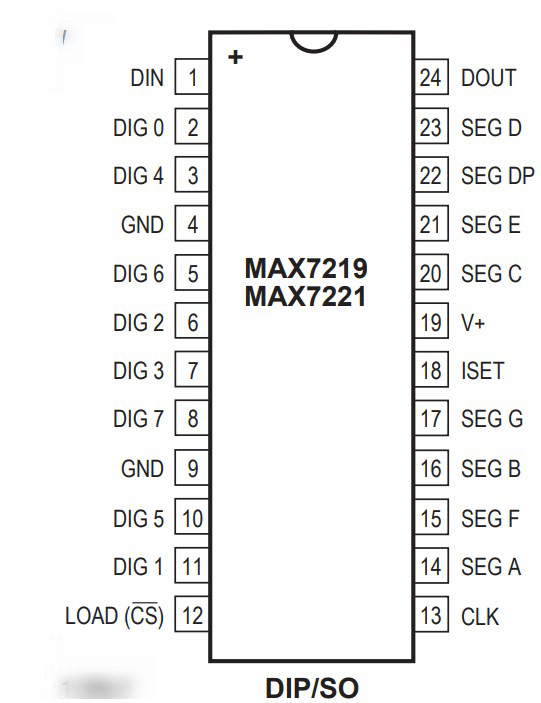
The below table summarises the pins and the function of each pin.
| Pin Number | Pin Name | Pin Description |
| 1 | DIN | Serial-Data Input. Data is loaded into the internal 16-bit shift register on CLK’s rising edge. |
| 2 | DIG 0 | Digit 0 drive line that sinks current from the common display cathode. The MAX7219 pulls the digit outputs to V+ when turned off. |
| 3 | DIG 4 | Digit 4 drive line that sinks current from the common display cathode. |
| 4 | GND | Ground |
| 5 | DIG 6 | Digit 6 drive line that sinks current from the common display cathode. |
| 6 | DIG 2 | Digit 2 drive line that sinks current from the common display cathode. |
| 7 | DIG 3 | Digit 3 drive line that sinks current from the common display cathode. |
| 8 | DIG 7 | Digit 7 drive line that sinks current from the common display cathode. |
| 9 | GND | Ground |
| 10 | DIG 5 | Digit 5 drive line that sinks current from the common display cathode. |
| 11 | DIG 1 | Digit 1 drive line that sinks current from the common display cathode. |
| 12 | LOAD | Load-Data Input. The last 16 bits of serial data are latched on LOAD’s rising edge. |
| 13 | CLK | Serial clock input |
| 14 | SEG A | Seven Segment Drives and Decimal Point Drive that source current to the display. |
| 15 | SEG F | Seven Segment Drives and Decimal Point Drive that source current to the display. |
| 16 | SEG B | Seven Segment Drives and Decimal Point Drive that source current to the display. |
| 17 | SEG G | Seven Segment Drives and Decimal Point Drive that source current to the display. |
| 18 | ISET | Connect to VDD through a resistor (RSET) to set the peak segment current |
| 19 | V+ | Positive supply voltage ( +5 V) |
| 20 | SEG C | Seven Segment Drives and Decimal Point Drive that source current to the display. |
| 21 | SEG E | Seven Segment Drives and Decimal Point Drive that source current to the display. |
| 22 | SEG DP | Seven Segment Drives and Decimal Point Drive that source current to the display. |
| 23 | SEG D | Seven Segment Drives and Decimal Point Drive that source current to the display. |
| 24 | DOUT | Serial data output. This pin is also used to daisy chain |
Step-By-Step Instructions To Connect The MAX7219 7-segment Display Module With Arduino UNO
In this section, we will build a project using Arduino UNO, MAX7219, and the 7-segment display module.
The connections are easy to take significantly less time to complete.
How To Connect The display module MAX7219 To The Arduino UNO?
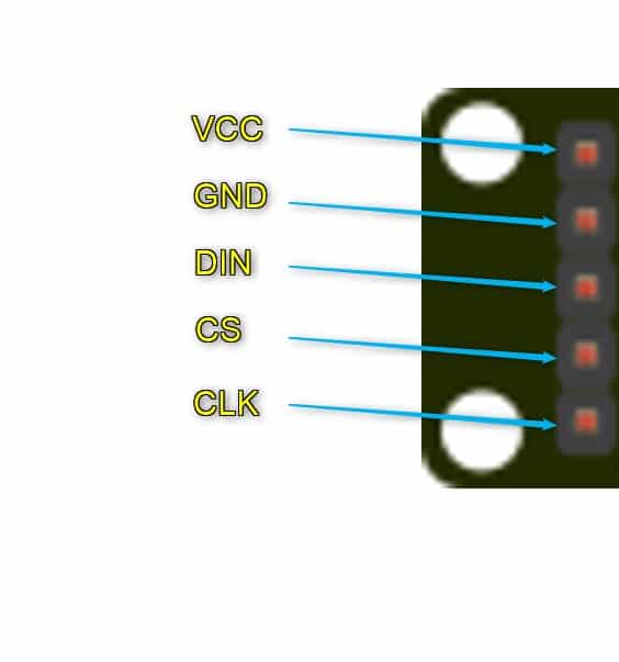
Below is the step-by-step connection guide to complete the Arduino and the MAX7219 Module. Let’s look at the module.
In the provided image, you can see five pins that are available for connecting the module to an Arduino UNO.
Each of these pins is labeled for easy identification.
With the MAX7219, it’s possible to control as many as 64 LEDs. That means you can use just one MAX7219 integrated circuit to control an 8-digit display panel.
Let’s start!
Step 1: Start with the GND (Ground) connections
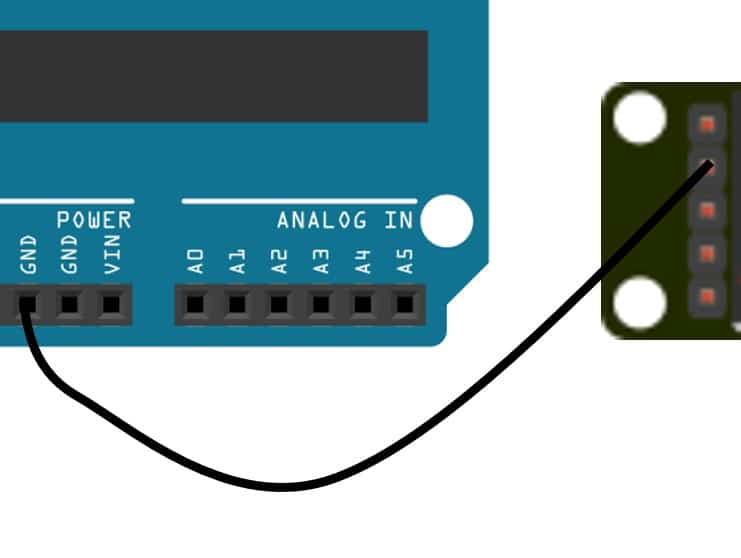
Connect the GND pin of the module to the GND of the Arduino.
Choose any GND pins available on the Arduino for the connection.
It is an excellent practice to start with the GND connections.
Step 2: Connect the DIN (Data In) Line (yellow wire)
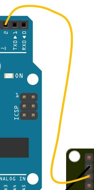
Connect the DIN pin on the MAX7219 display module to the Pin2 of the Arduino UNO.
Step 3: Connect the CS (Chip Select) pin (green wire)
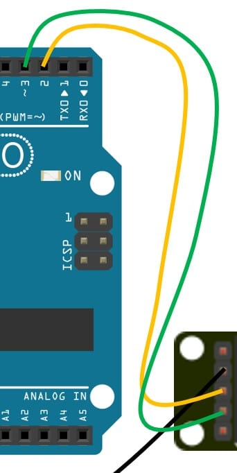
Connect the CS (Chip Select) pin on the module to Pin 3 of the Arduino UNO.
Step 4: Connect the CLK (Clock) pin (blue wire)
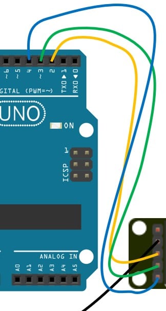
Connect the CLK pin of the module to the Arduino pin 4.
Step 5: Connect the Power pin
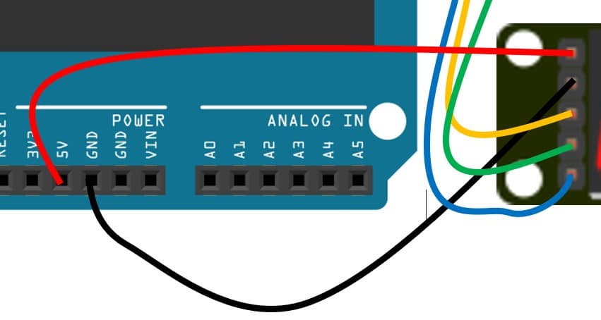
You can now connect the VCC pin of the MAX7219 display module to the Arduino UNO.
It is a good practice to complete all other connections before you connect the VCC pins.
Hence, we connected VCC pins in the last step.
Step 6: Complete connection
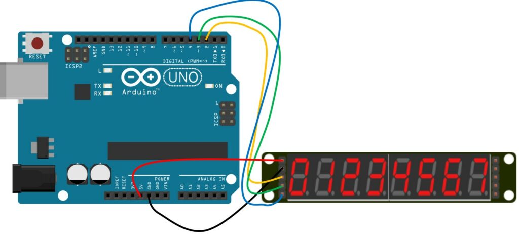
Congratulations! This completes all the required connections.
Arduino Code Example For The MAX7219 7-segment Module Project
In this section, you can find the complete Arduino sketch and the information on installing the necessary libraries.
/*  7 segment display MAX7219 driver serial control
  Schematic: https://www.electronoobs.com/eng_arduino_tut54_sch1.php
  Code: https://www.electronoobs.com/eng_arduino_tut54_code1.php
*/

#define MAX7219_Data_IN 2
#define MAX7219_Chip_Select  3
#define MAX7219_Clock 4

byte adr = 0x08;
byte num = 0x00;
int i = 0;

void shift(byte send_to_address, byte send_this_data)
{
  digitalWrite(MAX7219_Chip_Select, LOW);
  shiftOut(MAX7219_Data_IN, MAX7219_Clock, MSBFIRST, send_to_address);
  shiftOut(MAX7219_Data_IN, MAX7219_Clock, MSBFIRST, send_this_data);
  digitalWrite(MAX7219_Chip_Select, HIGH);
}

void setup() {
  pinMode(MAX7219_Data_IN, OUTPUT);
  pinMode(MAX7219_Chip_Select, OUTPUT);
  pinMode(MAX7219_Clock, OUTPUT);
  digitalWrite(MAX7219_Clock, HIGH);
  delay(200);

  //Setup of MAX7219 chip
  shift(0x0f, 0x00); //display test register - test mode off
  shift(0x0c, 0x01); //shutdown register - normal operation
  shift(0x0b, 0x07); //scan limit register - display digits 0 thru 7
  shift(0x0a, 0x0f); //intensity register - max brightness
  shift(0x09, 0xff); //decode mode register - CodeB decode all digits
}

void loop() {
  //Data transfer
  shift(0x08, 0x00); //digit 7 (leftmost digit) data
  shift(0x07, 0x01);
  shift(0x06, 0x02);
  shift(0x05, 0x03);
  shift(0x04, 0x04);
  shift(0x03, 0x05);
  shift(0x02, 0x06);
  shift(0x01, 0x07); //digit 0 (rightmost digit) data
  delay(1000);
  shift(0x08, 0x07); //digit 7 (leftmost digit) data
  shift(0x07, 0x06);
  shift(0x06, 0x05);
  shift(0x05, 0x04);
  shift(0x04, 0x03);
  shift(0x03, 0x02);
  shift(0x02, 0x01);
  shift(0x01, 0x00); //digit 0 (rightmost digit) data
  delay(1000);
}
Let’s walk through the code.
#define MAX7219_Data_IN 2
#define MAX7219_Chip_Select  3
#define MAX7219_Clock 4
These three lines specify which Arduino pins are connected to the control pins of the MAX7219 module. It’s important to ensure that this block definition matches the actual wiring of the circuit.
  //Setup of MAX7219 chip
  shift(0x0f, 0x00); //display test register - test mode off
  shift(0x0c, 0x01); //shutdown register - normal operation
  shift(0x0b, 0x07); //scan limit register - display digits 0 thru 7
  shift(0x0a, 0x0f); //intensity register - max brightness
The code above is used to configure the MAX7219 integrated circuit. It informs the IC that there are eight digits connected to the module, which will be driven by the 7-segment display.
Additionally, the code sets the brightness level to its maximum setting.
FAQs About The 7-segment Driver MAX7219 And The Arduino UNO Projects
I have included a list of the most frequently asked questions about projects built using Arduino and the module – MAX7219. If you have more questions, please post them in the comments section.
1. What is the MAX7219 IC?
The MAX7219 IC is a serial input/output common-cathode display driver that can interface microprocessors to 7-segment numeric LED displays of up to 8 digits, bar-graph displays, or 64 individual LEDs.
2. How does the MAX7219 IC save pins on my microcontroller?
The MAX7219 IC uses a simple serial interface to control the 7-segment displays, eliminating the need for multiple data and control pins on the microcontroller. This allows for more efficient use of pins and reduces the complexity of the circuit.
3. What are the operating voltage and current consumption of the MAX7219 IC?
The operating voltage of the MAX7219 IC is 4V to 5.5V, and it has a low current consumption. This makes it a robust and reliable choice for various low-power display applications.
4. What are some common applications of the MAX7219 IC?
The MAX7219 IC has a wide range of applications, such as digital clocks, electronic scoreboards, LED matrix displays, industrial control, gaming, and educational purposes.
The 7-segment display can find applications in displaying attendance counters, numbers in production lines, temperature and medical information in hospitals, weighing machines, sensor displays, weather displays, and more!
5. Can the MAX7219 IC control individual LEDs?
Yes, the MAX7219 IC can control up to 64 individual LEDs. It is not limited to only controlling 7-segment displays.
6. Can I use the MAX7219 IC to control a bar-graph display?
Yes, the MAX7219 IC can also be used to control bar-graph displays in addition to 7-segment displays and individual LEDs!
You can use up to 8 LED bar graphs with 8 LED each with one MAX7219 chip.
7. Are MAX7219 nad MAX7221 different?
MAX7219 nad MAX7221 are identical except for two features:
- The MAX7221 segment drivers are slew-rate limited to reduce EMI
- The MAX7221 supports a serial interface that is fully SPI compatible
Conclusion
In this article, I provided all the information you need to get started with the MAX7219 and 7-segment display for your Arduino projects.
I have shared all the basic information along with the applications and features of the MAX7219 and provided a step-by-step connection guide and working code examples to help you get started quickly.
If you have any questions or feedback, feel free to reach out. I’d love to hear from you and improve this guide if needed.
Also, don’t forget to share with your fellow Arduino enthusiasts.
Let me know which topic would you love to read about next! Happy tinkering!

I am Puneeth. I love tinkering with open-source projects, Arduino, ESP32, Pi and more. I have worked with many different Arduino boards and currently I am exploring, Arduino powered LoRa, Power line communication and IoT.
Arko
Tuesday 14th of November 2023
Thanks for the handy tutorial, great job. You've mixed up step 3, which is the CS (Chip Select) and step 4, which is CLK (Clock).
The code check out though.
Stefan Maetschke
Wednesday 15th of November 2023
Good catch! Thanks for the help. The error has been fixed.