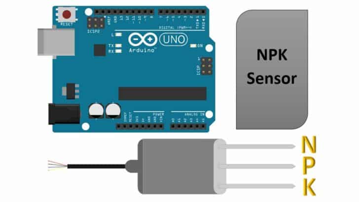
In this article, you learn about using NPK sensors with Arduino.
NPK (Nitrogen, Phosphorus, and Potassium) are plants’ three vital macronutrients.
You can use the NPK sensor to monitor the nutrition content available for plants in the soil.
It can be used as part of your garden projects, perhaps alongside an automated Arduino IoT plant watering system.
There are several types of sensors available to monitor the soil nutrients.
The NPK sensors used in this project are accurate, and the results are available immediately.
You will need a level converter to connect the Arduino UNO to the NPK sensor.
Below, you will find the converter details, a step-by-step connection diagram, and the NPK sensor pins.
In the later sections, you will find the Arduino code and a collection of frequently asked questions about the NPK projects with answers.
Let’s get started!
Components Needed To Build Arduino And NPK Sensor
Hardware Components
- Dupont wire x 1 set
- Arduino USB cable (for powering Arduino and programming) x 1
Software
Makerguides.com is a participant in the Amazon Services LLC Associates Program, an affiliate advertising program designed to provide a means for sites to earn advertising fees by advertising and linking to products on Amazon.com.
Basics Of NPK Sensor
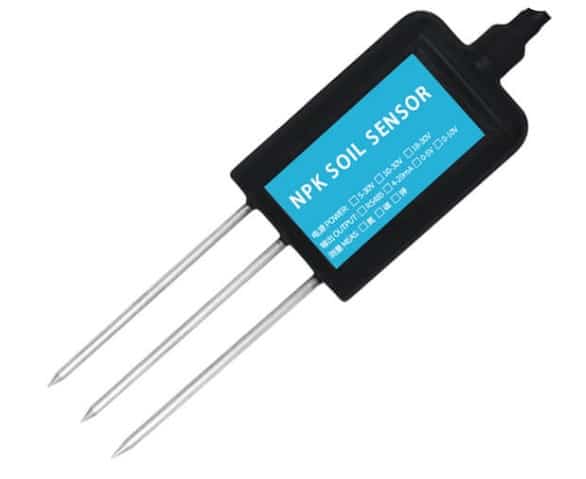
In this section, we will learn about the NPK sensor details.
The typical NPK sensor is shown in the image below.
The sensors contain all the electronics needed to sample the data, process it, and communicate it with the host controllers over the RS485 protocol.
Let us see the pin details of the typical NPK soil nutrient sensor.
You can use Modbus to get the data of all three elements’ concentrations in the soil.
You can send independent enquiries over the bus to collect the nitrogen, potassium, and phosphorus measurement data.
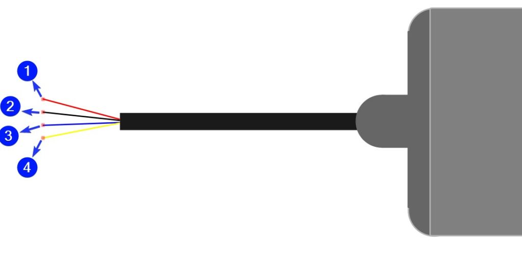
The NPK sensor has four wires available for the connection:
| Pin Number | Pin Description | Remarks |
| 1 | VCC | Power line communication |
| 2 | GND | Ground connection |
| 3 | RS485A | RS485 communication line A |
| 4 | RS485B | RS485 communication line B |
You can measure the quantity of nitrogen, phosphorus, and potassium in the soil.
Once you have the measurements, you can evaluate the soil condition effectively.
The NPK sensors can be left in the ground for longer times.
You can measure the data over a long period and give proper feedback to the team who applies the fertilizers.
The NPK sensors are used in agriculture research, gardening, forestry, cultivation, and much more.
What are the generic features of ideal NPK sensors?
Here is the list of desired NPK sensor features for soil nutrient study applications
- Easy to use interface and preferably less number of steps
- No active harmful chemicals.
- Any number of readings should be possible.
- Response time should be significantly less – Once you issue the commands, the measurements should be completed in the least time possible.
- The sensors should be resistant to corrosion – You can leave the sensor buried in the soil for longer.
Step-By-Step Instructions To Connect The NPK Sensor Module To The Arduino UNO
In this section, we will build a project using Arduino UNO and the NPK sensor module.
The NPK sensor module I am using provides data over the RS485 protocol.
Since we cannot directly connect the RS485 bus to the Arduino UNO, we will use a TTL to RS485 converter.
Let’s begin.
We will use an RS485 to TTL converter. Let’s see the pin descriptions of the module.
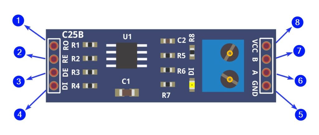
The table below defines the pins in the order they are labelled as per the image above.
| Pin number | Pin Description | Remarks |
| 1 | Receive Out | If A > B by 200mV, RO will be high; If A < B by 200mV, RO will be low |
| 2 | Receive Enable | Receiver Output Enable. RO is enabled when RE is low; RO is high impedance when RE is high |
| 3 | Data Enable | Driver Output Enable. The driver outputs, Y and Z, are enabled by bringing DE high. They are high impedance when DE is low. If the driver outputs are enabled, the parts function as line drivers. While they are high impedance, they function as line receivers if RE is low. |
| 4 | Data In | Driver Input. A low on DI forces output Y to low and output Z to high. Similarly, a high on DI forces output Y high and output Z low. |
| 5 | GND | Ground connection |
| 6 | A | Non-inverting receiver input |
| 7 | B | Inverting receiver input |
| 8 | VCC | Positive supply, 5V typical |
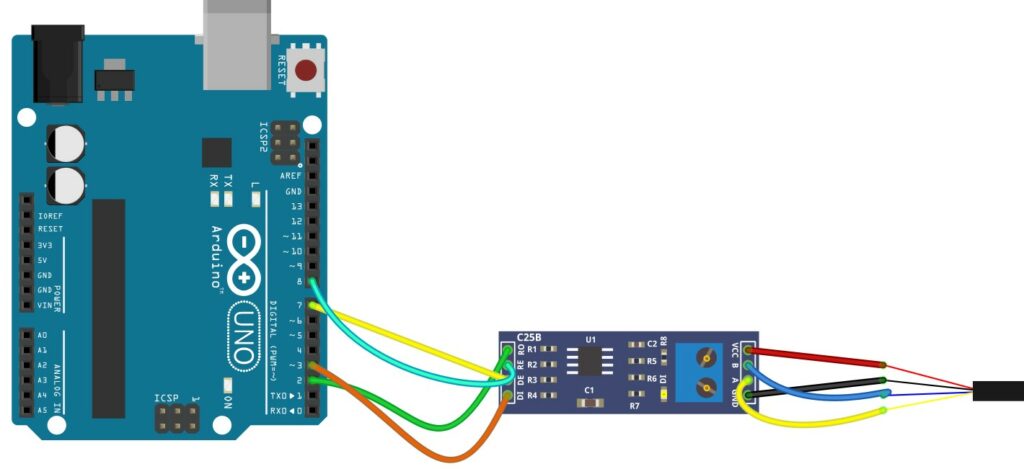
How To Connect The NPK Sensor Module To The Arduino UNO?
Below is the step-by-step guide to complete the hardware connections needed to connect the Arduino and the NPK sensor module.
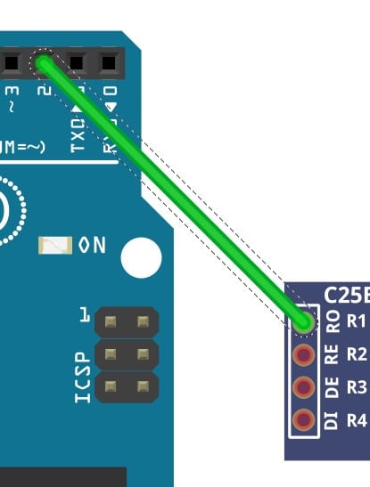
Step 1: Start with the GND connections.
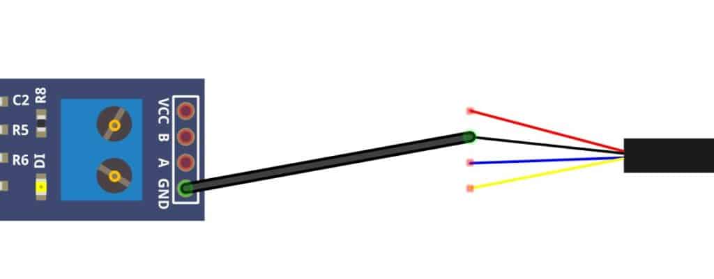
Connect the ground pin of the RS485 converter module to the ground wire of the NPK sensor.
Always connect the grounds together before making other connections.
Step 2: Connect the A and B pins of the Sensor
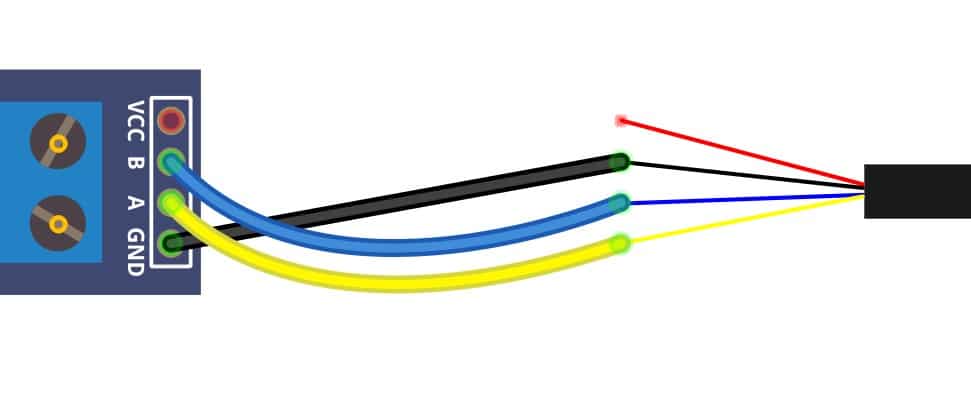
Connect the inverting and the noninverting terminals of the RS485 module to the A and B pins of the NPK sensor.
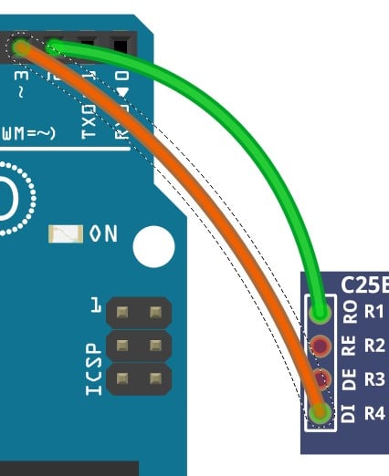
Step 3: Connect the Power pin
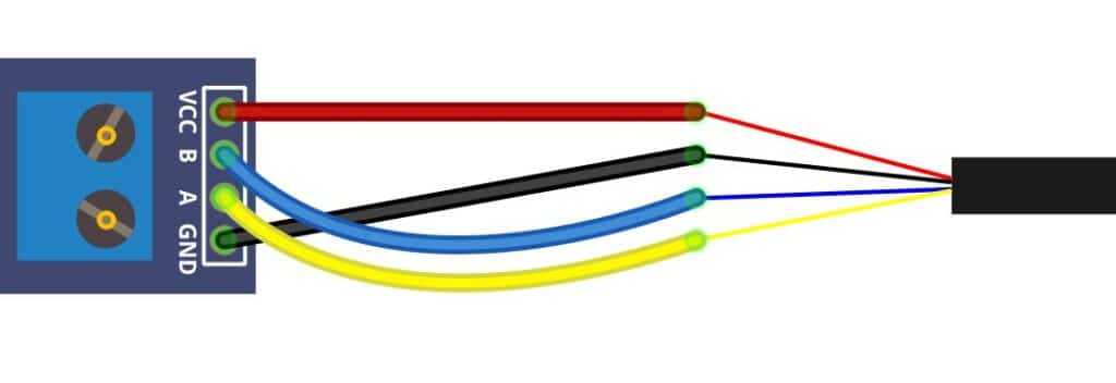
Connect the VCC pin of the module to the VCC wire of the NPK sensor.
Step 4: Verify the connection between RS485 converter and the NPK Sensor
This completes the necessary connections between the RS485 module and the NPK sensor.
In the next steps, we will connect the Arduino UNO to the RS485 module.
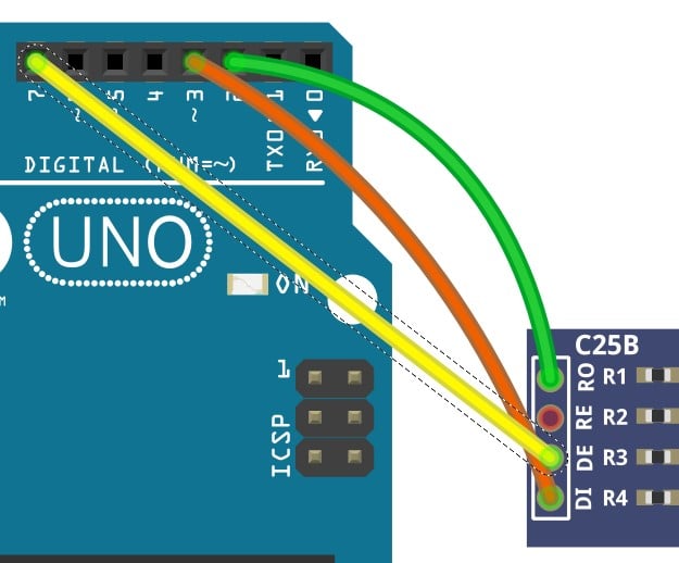
Step 5: Connect RO Pin the UNO
Connect the pin 2 to the RO pin of the RS485 sensor.
Step 6: Connect DI Pin the UNO
Connect the pin 3 to the RO pin of the RS485 sensor.
Step 7: Connect DE Pin the UNO
Connect the pin DE of the module to the Arduino UNO’s pin 7.
Step 8: Connect RE Pin the UNO
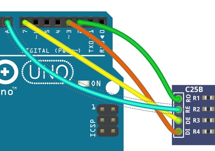
Connect the pin RE of the module to the Arduino UNO’s pin 8.
You can also decide to swap the connections with other pins on the Arduino UNO.
Please also update your Arduino code, so the new connections work.
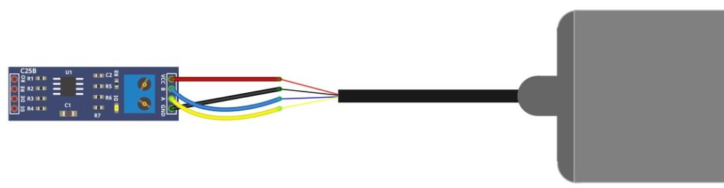
Step 9: Verify the complete connections
Verify the connections. Congratulations on completing the connections needed to read the NPK sensors.
Arduino Code Example For The Arduino And The NPK Sensor Project
In this section, we will walk through the example Arduino code to test the NPK sensor module.
The first project tests the circuit you built in the previous section.
Let’s get started.
Arduino Code to display the NPK Sensor data
The Arduino code below reads the NPK sensor data over RS485. The Arduino code is presented below.
#include "SoftwareSerial.h"
#include "Wire.h"
#include "Adafruit_GFX.h"
#include "Adafruit_SSD1306.h"

#define SCREEN_WIDTH 128    // OLED display width, in pixels
#define SCREEN_HEIGHT 64    // OLED display height, in pixels
#define OLED_RESET -1       // Reset pin # (or -1 if sharing Arduino reset pin)
Adafruit_SSD1306 display(SCREEN_WIDTH, SCREEN_HEIGHT, &Wire, OLED_RESET);

#define RE 8
#define DE 7

const byte nitro[] = {0x01, 0x03, 0x00, 0x1e, 0x00, 0x01, 0xe4, 0x0c};
const byte phos[] = {0x01, 0x03, 0x00, 0x1f, 0x00, 0x01, 0xb5, 0xcc};
const byte pota[] = {0x01, 0x03, 0x00, 0x20, 0x00, 0x01, 0x85, 0xc0};

byte values[11];
SoftwareSerial mod(2, 3);

void setup() {
  Serial.begin(9600);
  mod.begin(9600);
  pinMode(RE, OUTPUT);
  pinMode(DE, OUTPUT);

  display.begin(SSD1306_SWITCHCAPVCC, 0x3C); //initialize with the I2C addr 0x3C (128x64)
  delay(500);
  display.clearDisplay();
  display.setCursor(25, 15);
  display.setTextSize(1);
  display.setTextColor(WHITE);
  display.println(" NPK Sensor");
  display.setCursor(25, 35);
  display.setTextSize(1);
  display.print("Initializing");
  display.display();
  delay(3000);
}

void loop() {
  byte val1, val2, val3;
  val1 = nitrogen();
  delay(250);
  val2 = phosphorous();
  delay(250);
  val3 = potassium();
  delay(250);

  Serial.print("Nitrogen: ");
  Serial.print(val1);
  Serial.println(" mg/kg");
  Serial.print("Phosphorous: ");
  Serial.print(val2);
  Serial.println(" mg/kg");
  Serial.print("Potassium: ");
  Serial.print(val3);
  Serial.println(" mg/kg");
  delay(2000);

  display.clearDisplay();

  display.setTextSize(2);
  display.setCursor(0, 5);
  display.print("N: ");
  display.print(val1);
  display.setTextSize(1);
  display.print(" mg/kg");

  display.setTextSize(2);
  display.setCursor(0, 25);
  display.print("P: ");
  display.print(val2);
  display.setTextSize(1);
  display.print(" mg/kg");

  display.setTextSize(2);
  display.setCursor(0, 45);
  display.print("K: ");
  display.print(val3);
  display.setTextSize(1);
  display.print(" mg/kg");

  display.display();
}

byte nitrogen() {
  digitalWrite(DE, HIGH);
  digitalWrite(RE, HIGH);
  delay(10);
  if (mod.write(nitro, sizeof(nitro)) == 8) {
    digitalWrite(DE, LOW);
    digitalWrite(RE, LOW);
    for (byte i = 0; i < 7; i++) {
      //Serial.print(mod.read(),HEX);
      values[i] = mod.read();
      Serial.print(values[i], HEX);
    }
    Serial.println();
  }
  return values[4];
}

byte phosphorous() {
  digitalWrite(DE, HIGH);
  digitalWrite(RE, HIGH);
  delay(10);
  if (mod.write(phos, sizeof(phos)) == 8) {
    digitalWrite(DE, LOW);
    digitalWrite(RE, LOW);
    for (byte i = 0; i < 7; i++) {
      //Serial.print(mod.read(),HEX);
      values[i] = mod.read();
      Serial.print(values[i], HEX);
    }
    Serial.println();
  }
  return values[4];
}

byte potassium() {
  digitalWrite(DE, HIGH);
  digitalWrite(RE, HIGH);
  delay(10);
  if (mod.write(pota, sizeof(pota)) == 8) {
    digitalWrite(DE, LOW);
    digitalWrite(RE, LOW);
    for (byte i = 0; i < 7; i++) {
      //Serial.print(mod.read(),HEX);
      values[i] = mod.read();
      Serial.print(values[i], HEX);
    }
    Serial.println();
  }
  return values[4];
}
FAQs About The NPK Sensor And Arduino Projects
I have included a list of the most frequently asked questions about projects built using Arduino and the NPK sensor modules.
If you have further questions, kindly post them in the comments section.
I will be glad to answer them.
1. What is an NPK sensor?
NPK stands for Nitrogen, Phosphorus, and potassium.
NPK sensors are used to detect the fertility of the soil. The NPK sensors are used to evaluate the nature of the soil.
Monitoring the agricultural land for fertility helps you increase the yield, avoiding unwanted excess usage of fertilizers and polluting the natural essence of the soil.
An NPK sensor is powered using a 5 V to 24 V supply. Refer to the specifications of the particular sensor for accurate information on the voltage range.
The sensor also supports RS485 or a similar communication interface.
In this article, we have used the RS485 protocol to communicate with the Arduino UNO.
2. Is an NPK sensor accurate?
The NPK sensors are easy to use and very accurate.
The NPK sensors provide a way to measure the soil Nitrogen, Phosphorus, and potassium levels.
The readings are fast, accurate, and easy to process.
The typical NPN sensor data is accurate, the response time is faster, and you can bring several NPK sensors on a shared serial bus.
3. Why is NPK value important?
NPK represents the most essential macronutrient of the soil. If you know the NPK value in the soil, you can nurture your garden plants with the right level of nutrients.
If you exceed the preferred range of NPK, the natural essence of the soil will be lost.
If you reduce the number of nutrients, the plant will suffer. Hence NPK sensors play a vital role in balancing the NPK contents.
4. Which of the NPK is most important?
Out of the three elements, Nitrogen is critical for a plant’s development.
The NPK values are vital in building the plant structure, seed generation, flowers, etc.
The NPK fertilizers should be applied when the plant is growing actively.
NPK sensors can be used to actively monitor the nutritional information of the soil.
Conclusion
In this article, we understood the basics of an NPK sensor and how the NPK sensor measures the NPK contents of the soil.
We also listed the features of an NPK sensor, and learned the basics of the RS485 to TTL converter used in the project.
You can follow the connection steps and complete the circuit for our soil nutrition monitoring project.
The Arduino code to read the NPK sensors presented is easy and straightforward to understand.
Please post your questions on the NPK sensors in the comments section. I am always happy to answer them.
If you have any feedback to improve the article, please share it in the comments section.
Your valuable input helps me to improve the article quality and bring more helpful articles down the line.
Please remember to share the article with your fellow Arduino enthusiasts.

I am Puneeth. I love tinkering with open-source projects, Arduino, ESP32, Pi and more. I have worked with many different Arduino boards and currently I am exploring, Arduino powered LoRa, Power line communication and IoT.
Robert
Friday 1st of December 2023
Thank you for this interesting article! One question: Do you think this type of NPK sensor works also for hydroponics? I.e. will it provide reliable results when using in a fluid nutrient solution? Many thanks in advance, Robert
Stefan Maetschke
Saturday 2nd of December 2023
Good questions, I don't know. Never tried this.
Georgio
Friday 18th of August 2023
Is it simple to add a humidity sensor to this project?
Lorena
Thursday 7th of September 2023
@Stefan, Hi, I have two questions 1. What are the pins for OLED? In this exercise, 2. may do you know the circuit and code using ESP32? If you can help means a lot!!! Thank you!
Georgio
Wednesday 23rd of August 2023
@Stefan, Thanks for your rapid reply. I confess, as a newbie, that I don't follow how to combine the 2 projects into one, since they use different components and there's the whole IoT thing which I'm not sure I care about. I have seen more complicated sensors available, with 5 or 7 prongs that test more things, but I haven't been able to find a tutorial on making an NPK, humidity, PH sensor with them. So that, in the end, was my question. Again, as a newbie, I'd love to find a comprehensive how-to, like the one on this page, but for the expanded project.
Stefan
Saturday 19th of August 2023
Sure, the following tutorial shows how to use a humidity and moisture sensor: https://www.makerguides.com/automatic-plant-watering-system-with-arduino-iot-cloud/
afzal
Friday 24th of March 2023
give complete circuit diagram with oled