Radio frequency Identification (RFID) technology has brought great comfort to our daily lives and has revolutionized the world.
From automatically detecting items you have bought at the counter, to tracking inventory across the world, or providing access to office spaces.
In this article, we will learn how to interface an RFID reader with Arduino UNO.
We will connect the RFID controller to the Arduino UNO. We will list all the applications of RFID readers.
I’ll go through step-by-step instructions to complete the Arduino and RFID module circuit.
In the later sections, we will see Arduino code examples for you to utilise.
At the end of the article, you will find a collection of the most frequently asked questions on the RFID modules with answers.
Let’s get started.
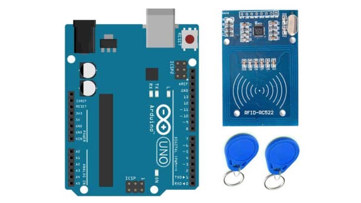
Components Needed To Build Arduino RFID Project
Hardware Components
- Arduino Uno Rev3 x 1
- Reader Module Kit Mifare RC522 Reader Module with S50 x 1
- White Card+Key Ring Reader x 1
- Dupont wire x 1 set
- Arduino USB cable (for powering Arduino and programming) x 1
Software
Makerguides.com is a participant in the Amazon Services LLC Associates Program, an affiliate advertising program designed to provide a means for sites to earn advertising fees by advertising and linking to products on Amazon.com.
Basics of The RFID Technology
In this section, I will briefly explain what RFID is, how RFID works, and also list the applications of RFID technology.
What is RFID?
RFID stands for Radio Frequency Identification. RFID technology can help you to track people’s movement, update inventory, etc.
A basic working RFID system involves a receiver, transmitter, and transponder. The RFID tags are the receivers.
You can also find RFID tags that are self-powered.
They have a wider range of communication when compared to passive tags.
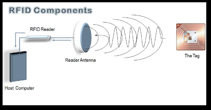
The transponder sends an electromagnetic field when triggered.
When in the transmitter’s range, the RFID receiver couples with the signal and responds digitally.
The transponder will decode the signals and identifies the tag.
What are the features of RFID?
I’ll list the features of RFID here.
- Unique ID – Every RFID contains an individual ID. When you use the RFID tag to enter a gate or authenticate a product, the computers operating the transponders can automatically update the database. The unique ID helps in sorting packages, tracking goods during transportation, and animal husbandry.
- No batteries needed – One of the prime features of RFID technology is that the received tags don’t need to be powered. Hence the cost of maintenance is meager. You can also completely waterproof the tags, making them the most durable tracking device.
- It doesn’t depend on light or eyesight – The scanning can happen automatically. There is no need to make the tag always visible to the transponder. It can also be conveyed in a box, and the tracking will still work, which helps in improving both the response and processing time of goods.
- You can read multiple cards at the same time. Unlike a barcode reader, you can detect multiple cards in parallel. This helps in tracking numerous objects quicker.
What are the applications of RFID?
The applications of RFID technology are listed below.
- Access to workers in and out of the factories. The cards are usually the size of a credit card.
- Controlling access to restricted areas. The cards can be programmed to have limited access.
- Access control for guests in the hotels. The cards serve as keys that ease the entry and exit through the hotel facilities, such as pools, dining areas, and rooms.
- RFID tags are embedded in the clothes, which are used to enable automatic billing
- Counterfeit prevention – Every RFID can be tracked. By having a secure and unique ID for each product, one can quickly identify the fake ones.
- It can detect and track health in poultry and animal husbandry.
- You can also use it to track the assets such as monitors, test equipment, and other devices in and out of laboratories and update the database.
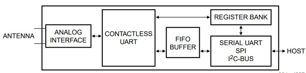
Features of the MFRC522 RFID Front end
MFRC522 is a commonly used transponder controller IC. The device supports the following features.
- Highly integrated analog circuitry to demodulate and decode responses
- Buffered output drivers for connecting an antenna with the minimum number of external components
- Supports ISO/IEC 14443 A/MIFARE and NTAG
- Operating distance – up to 5 cm
- SPI up to 10 Mbit/s
- I2C-bus interface up to 400 kHz in Fast mode, up to 3400 kHz in High-speed mode
- Hard reset with low power function – 10 uA in standby mode
- Power-down by software mode
- 2.5 V to 3.3 V power supply
The IC communicates with the Arduino over SPI or I2C.
The RFID reader can interrupt the Arduino whenever it detects a tag in its proximity.
Hence, you don’t have to use Arduino to poll the reader frequently.
You can put the Arduino into low-power mode and save power.
Pin Description
| Pin | Symbol | Description |
| 1 | I2C | I2C-bus enable input |
| 2 | PVDD | pin power supply |
| 3 | DVDD | digital power supply |
| 4 | DVSS | digital ground |
| 5 | PVSS | pin power supply ground |
| 6 | NRSTPD | reset and power-down input: |
| 7 | MFIN | MIFARE signal input |
| 8 | MFOUT | MIFARE signal output |
| 9 | SVDD | MFIN and MFOUT pin power supply |
| 10 | TVSS | transmitter output stage 1 ground |
| 11 | TX1 | transmitter 1 modulated 13.56 MHz energy carrier output |
| 12 | TVDD | transmitter power supply: supplies the output stage of transmitters 1 and 2 |
| 13 | TX2 | transmitter 2 modulated 13.56 MHz energy carrier output |
| 14 | TVSS | transmitter output stage 2 ground |
| 15 | AVDD | analog power supply |
| 16 | VMID | internal reference voltage |
| 17 | RX | RF signal input |
| 18 | AVSS | analog ground |
| 19 | AUX1 | auxiliary outputs for test purposes |
| 20 | AUX2 | auxiliary outputs for test purposes |
| 21 | OSCIN | crystal oscillator inverting amplifier input; also the input for an externally generated clock (fclk = 27.12 MHz) |
| 22 | OSCOUT | crystal oscillator inverting amplifier output |
| 23 | IRQ | interrupt request output: indicates an interrupt event |
| 24 | SDA | I2C-bus serial data line input/output |
| 25-31 | D1 | test port |
| 32 | EA | external address input for coding I2C-bus address |
Pinout of the RC522 RFID Module
The RFID module I have used in this project has the following pinouts.
| Sl. No. | Pin name | Description |
| 1 | VCC | Power supply to the module. You can supply 3.3 V from Arduino UNO 3.3 V. Do not connect 5 V from the UNO to the module. |
| 2 | RST | Resets the module on the rising edge. Pull this line to the ground to put the module in the power-down state. |
| 3 | GND | Ground connections. Connect the GND pin to Arduino UNO’s GND pin |
| 4 | IRQ | IRQ is the interrupt pin. RFID module uses this pin to interrupt Arduino |
| 5 | MISO / SCL / Tx | Master In Slave Out pin, I2C Clock line, acts as Transmit pin in the UART mode |
| 6 | MOSI | Master Out Slave In pin |
| 7 | SCK | Serial Clock pin |
| 8 | SS / SDA / Rx | Acts as chip select for SPI, I2C SPI data line, acts as Receive UART pin in UART mode. |
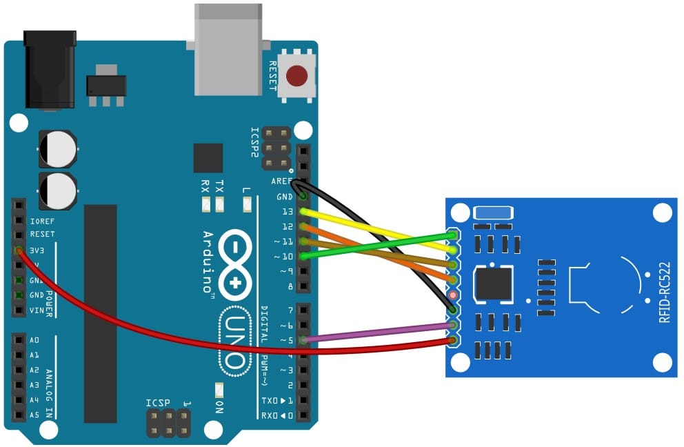
Step-By-Step Instructions To Connect The RFID RC422 With Arduino UNO
In this section, we will build a project using Arduino UNO and the RFID Reader module RC422.
The RC422 supports SPI and I2C protocols to communicate with Arduino.
I’ll use the SPI protocol in this example.
The connections are easy to make and take significantly less time to complete.
Let’s get started with the hardware connections!
How To Connect The RC422 RFID module to the Arduino UNO?
Below is the step-by-step connection guide to complete the Arduino and the RFID module connections.
Step 1: Start with the GND connections
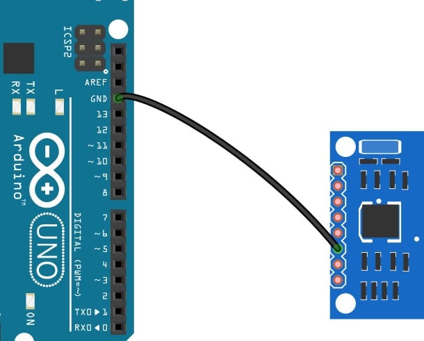
You can connect any GND pins of the Arduino UNO to the RFID module’s GND pin.
Step 2: Connect SPI Clock
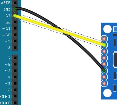
Connect pin SCL of the RFID module to pin 13 of the Arduino UNO.
Step 3: Connect the MISO pin
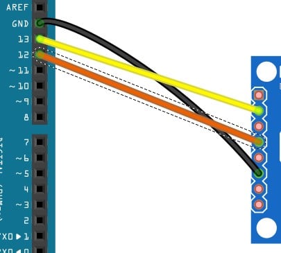
Connect the MISO pin on the RFID module to Arduino UNO’s pin 12.
Step 4: Connect the MOSI pin
Connect pin 11 of the Arduino UNO to the MOSI pin of the RFID module.
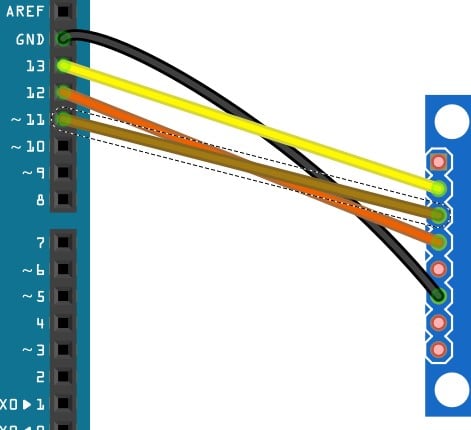
Step 5: Connect the SPI Slave connections
You can connect pin 10 of the UNO to the SDA pin (slave select of SPI) of the RFID module.
Step 6: Reset pin connection
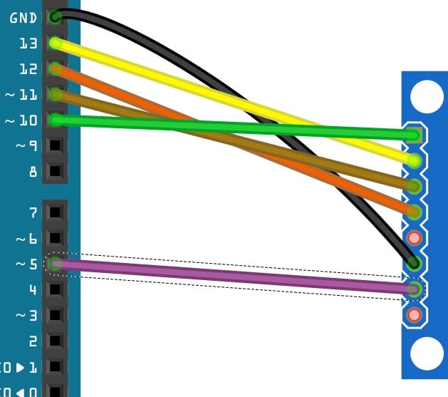
You can choose any free GPIO pin of the UNO to control the reset pin of the RFID module.
I have connected the RST pin to pin 5 of the UNO.
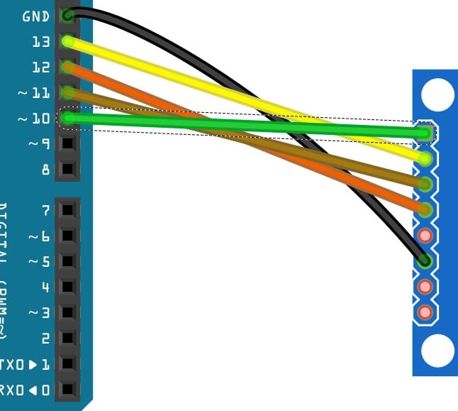
Step 7: Connect the power pin (3.3 V)
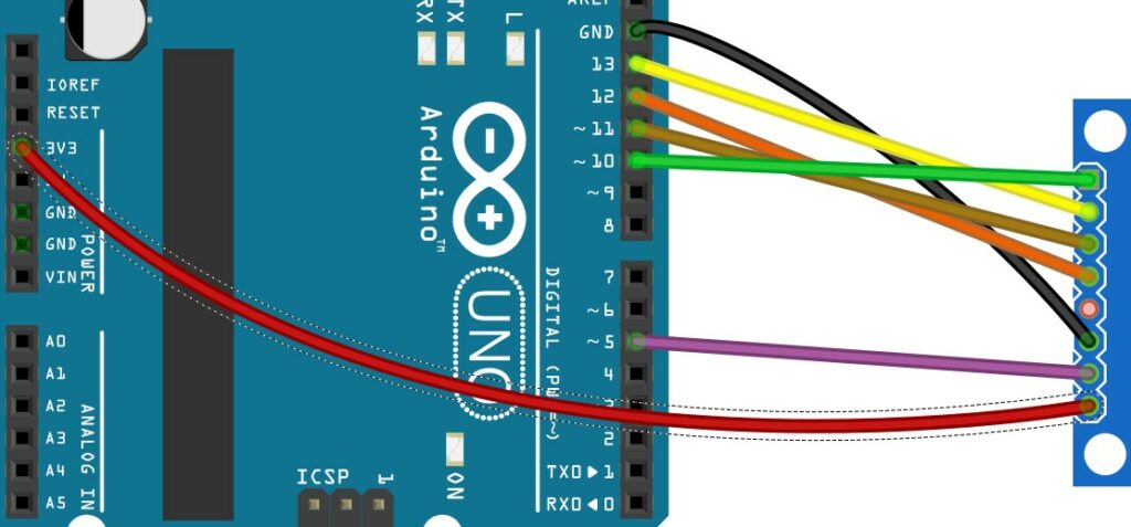
Connect 3.3 V of the UNO to the supply pin of the RFID module.
Step 8: Verify the complete connections
Congratulations. You have now completed the required connections. In the next section, I will present the Arduino code.
Arduino Code Example For The RFID Module Project
In this section, you can verify the connections and test the project you have built.
The amount of work needed to communicate with the RFID module is reduced when you use a readymade library.
Please install the RC422 library as shown in the image below.
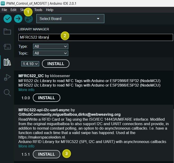
The complete Arduino code
This is an MFRC522 library example; for more examples, click here. You can copy paste the code in the editor window and compile the code.
Once you program teh Arduino, the project is ready to be tested.
Open the serial terminal to view the messages. You can bring an RFID tag near the RC422 reader.
You can read the ID, type and other data blocks which you can read on the terminal.
#include "SPI.h"
#include "MFRC522.h"

const uint8_t RST_PIN = 32;         // Configurable, see typical pin layout above
const uint8_t SS_PIN =  15;         // Configurable, see typical pin layout above

MFRC522_SPI spiDevice = MFRC522_SPI(SS_PIN, RST_PIN);
MFRC522 mfrc522 = MFRC522(spiDevice);  // Create MFRC522 instance


// Specify the wiring/pins in more detail.
//
// MFRC522_SPI spiDevice = MFRC522_SPI(SS_PIN, RST_PIN, PIN_SCK, PIN_MISO, PIN_MOSI);
// MFRC522 mfrc522 = MFRC522(spiDevice);
//
// Or do much the same - but also specify the bus
//
// SPI spiBus = SPI(HSPI);
// spiBus.begin(PIN_SCK, PIN_MISO, PIN_MOSI);
// MFRC522_SPI spiDevice = MFRC522_SPI(SS_PIN, RST_PIN, spiBus);
// MFRC522 mfrc522 = MFRC522(spiDevice);
//
// And if neeed - also change the bus settings.
//
// SPI spiBus = SPI(HSPI);
// SPISettings spiSettings = SPISettings(SPI_CLOCK_DIV4, MSBFIRST, SPI_MODE0))
// MFRC522_SPI spiDevice = MFRC522_SPI(SS_PIN, RST_PIN, spiBus, spiBusSettings);
// MFRC522 mfrc522 = MFRC522(spiDevice);


void setup() {
  Serial.begin(9600);   // Initialize serial communications with the PC
  while (!Serial);    // Do nothing if no serial port is opened (added for Arduinos based on ATMEGA32U4)

  SPI.begin(14, 12, 13);
  mfrc522.PCD_Init();   // Init MFRC522
  mfrc522.PCD_DumpVersionToSerial();  // Show details of PCD - MFRC522 Card Reader details
  Serial.println(F("Scan PICC to see UID, SAK, type, and data blocks..."));
}

void loop() {
  // Look for new cards
  if ( ! mfrc522.PICC_IsNewCardPresent()) {
    return;
  }

  // Select one of the cards
  if ( ! mfrc522.PICC_ReadCardSerial()) {
    Serial.println("Bad read (was card removed too quickly?)");
    return;
  }

  if (mfrc522.uid.size == 0) {
    Serial.println("Bad card (size = 0)");
  } else {
    char tag[sizeof(mfrc522.uid.uidByte) * 4] = { 0 };
    for (int i = 0; i < mfrc522.uid.size; i++) {
      char buff[5]; // 3 digits, dash and \0.
      snprintf(buff, sizeof(buff), "%s%d", i ? "-" : "", mfrc522.uid.uidByte[i]);
      strncat(tag, buff, sizeof(tag));
    };
    Serial.println("Good scan: ");
    Serial.println(tag);
  };

  // disengage with the card.
  mfrc522.PICC_HaltA();
}
FAQs About The RFID And Arduino Projects
I have included a list of the most frequently asked questions about projects built using Arduino and the RFID reader.
If you have more questions, please post them in the comments section.
I will be glad to answer them.
1. Can Arduino read RFID?
The Arduino UNO can communicate with an RFID reader to read RFID cards.
In this article, we have connected the RC522 RFID reader to the Arduino UNO over SPI.
Such RFID readers help build door access, package identifiers, etc.
2. How do you program an RFID reader?
You can program the RFID reader easily using Arduino UNO.
In this example, we went through model Arduino projects, where we saw how to update the Arduino code to update the RFID tag number to match the required tag numbers.
If you have several tags to which you want to allow access, you have to store all the tag numbers in the array.
Once you read the tag number from the RFID reader, you can check the tag numbers.
3. What are the three types of RFIDs?
You can classify three types of RFID tags based on the frequency range.
- Low Frequency – 30 to 300 kHz
- High Frequency – 3 to 30 MHz
- Ultra Low Frequency – 300 MHz to 3 GHz
Most of the hobby project modules I have seen are high-frequency range.
4. Can you store data in the RFID cards?
Some RFID cards allow you to store data on the card. One example is the RFID cards used in animal husbandry.
The cards can store the unique name assigned to the cattle and some basic information such as the latest weight data, last-time pregnancy data, etc.
Conclusion
In this article, we covered the basics of the RFID module RC422. The RFID module is easy to use and can be easily integrated into our projects.
I showed you how to complete the connections and program the Arduino to communicate with the RFID module.
I have used the RFID module to automatically scan and identify the packets so that the proper functions can be loaded into the label printer.
Later the printed label was pasted onto the box using a robotic arm.
If you have any feedback to improve the article, please share it in the comments section.
Your valuable input helps me to improve the article quality and bring more helpful content in the future.
Please remember to share the article with your fellow Arduino enthusiasts.

I am Puneeth. I love tinkering with open-source projects, Arduino, ESP32, Pi and more. I have worked with many different Arduino boards and currently I am exploring, Arduino powered LoRa, Power line communication and IoT.