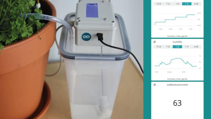
In this project, you will learn how to create an automatic indoor watering system with the Arduino IoT Cloud. This system allows you to monitor and water your plants from anywhere in the world and is a great introduction to the internet of things.
I have included build instructions, a getting started guide for the Arduino IoT Cloud and all the required code. This project uses an Arduino MKR1000 IoT board, a capacitive soil moisture sensor, temperature and humidity sensor, I2C LCD, and water pump. It is also possible to make this project with a normal Arduino (not connected to the internet).
Note that this is mainly a proof of concept, i.e., building this system for just one plant is quite expensive and probably doesn’t make a lot of sense. However, now that I know how everything works I can easily expand the system and add more features in the future.
If you have any questions or suggestions, please leave a comment below.
For more information about some of the components used in this project, check out the tutorials below:
Supplies
Hardware components
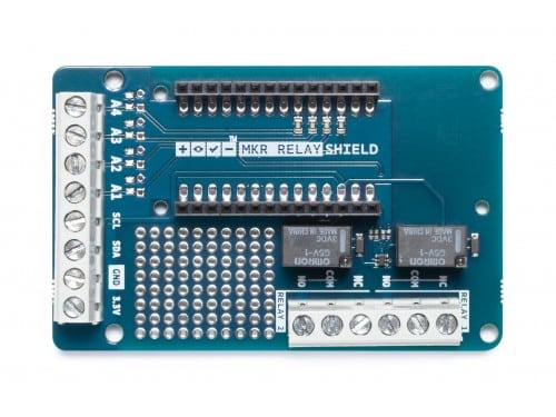
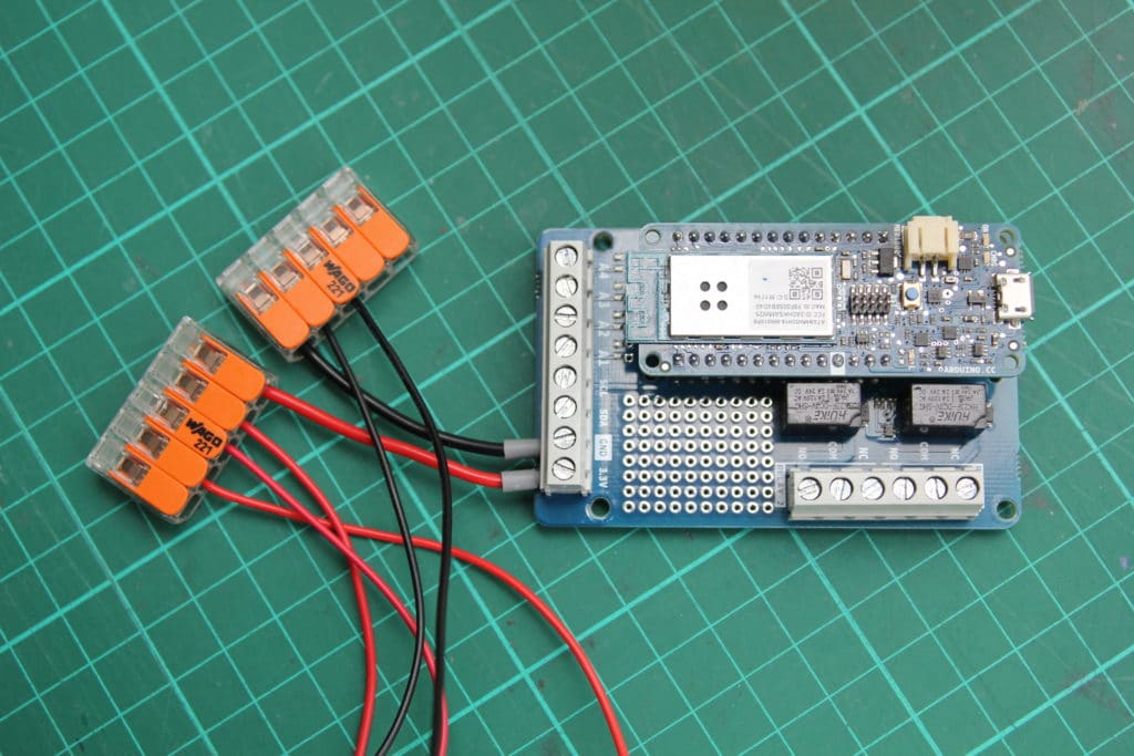
Note that you can also use any of the other Arduino IoT boards with Wi-Fi connectivity, like the Arduino MKR WiFi 1010 or the cheaper Arduino Nano 33 IoT. The advantage of the MKR boards is that they fit on the Arduino MKR Relay Proto Shield which makes wiring a lot easier.
For the water tank, you can use anything you have lying around (I used an IKEA food storage container from my kitchen).
Apps and online services

Makerguides.com is a participant in the Amazon Services LLC Associates Program, an affiliate advertising program designed to provide a means for sites to earn advertising fees by advertising and linking to products on Amazon.com. As an Amazon Associate we earn from qualifying purchases.
Assembling the system
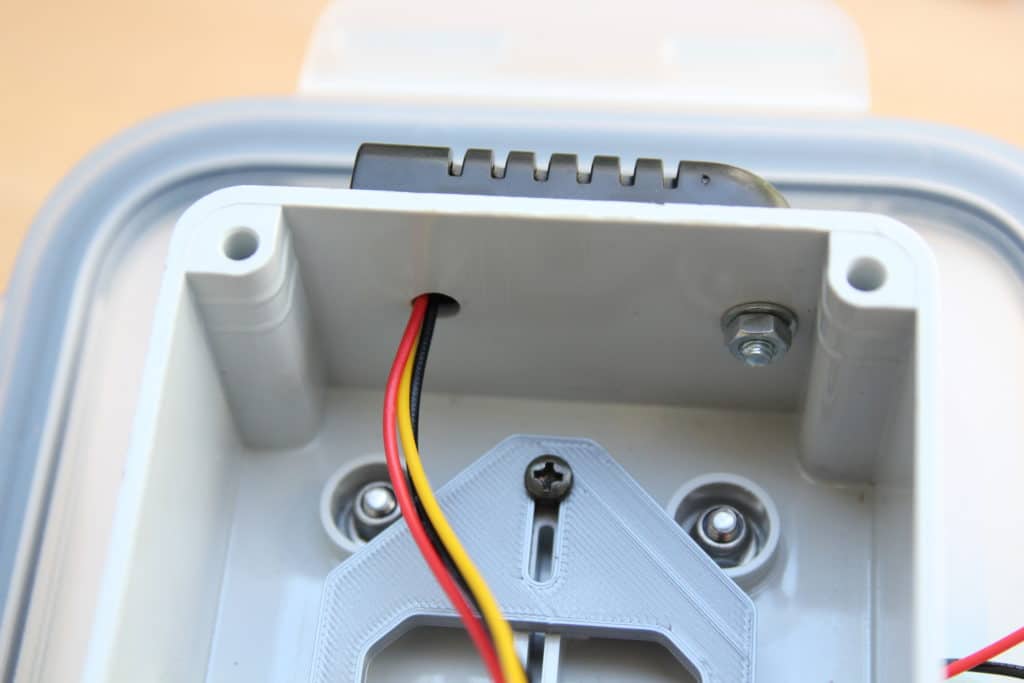
All of the components are connected to a central project box which is mounted on the lid of the IKEA container.
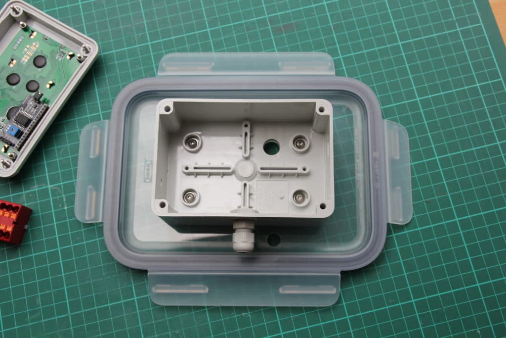
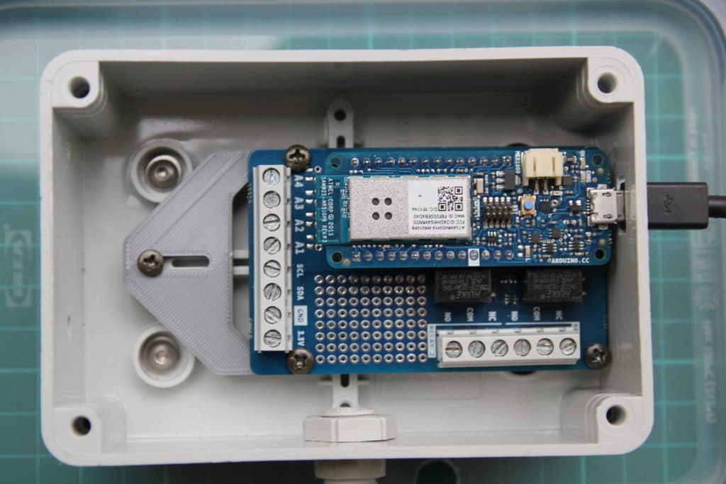
To mount the Arduino MKR Relay Proto Shield, I 3D printed a simple adapter plate. A small hole in the side of the project box provides access to the micro USB port of the MKR1000 which is used to power the system and to program the board.
Soil moisture sensor
For this project, I used a capacitive soil moisture sensor with an analog output. Capacitive sensors have better corrosion resistance than resistive sensors but they are not 100% waterproof. Since they are made from a standard PCB with a composite substrate, water can easily enter through the sides of the PCB. The electronics at the top of the sensor are also not protected from water in any way.
To make the sensor a bit more waterproof, I coated the edges and electronics with some clear nail polish. A real conformal coating is probably better but nail polish works quite well as a cheap alternative.
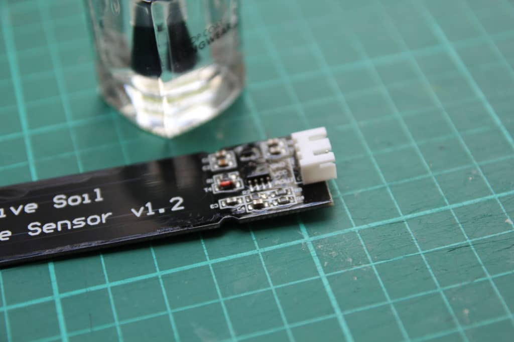
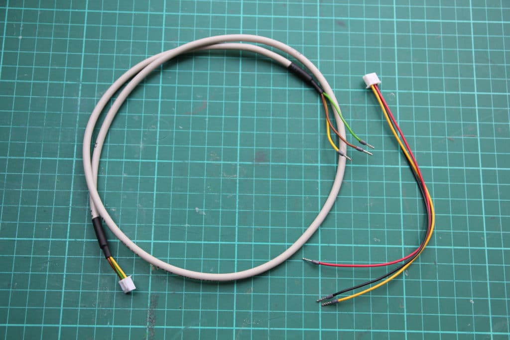
The cable that came with the sensor was quite short, so I made a new one. You can also just solder longer wires onto the original cable.
Connecting the soil moisture sensor to Arduino MKR1000
The table below shows you which connections you need to make.
| Soil moisture sensor | Arduino MKR1000 |
|---|---|
| GND | GND |
| VCC | 3.3 V |
| AOUT | A2 |
Pump and relay shield
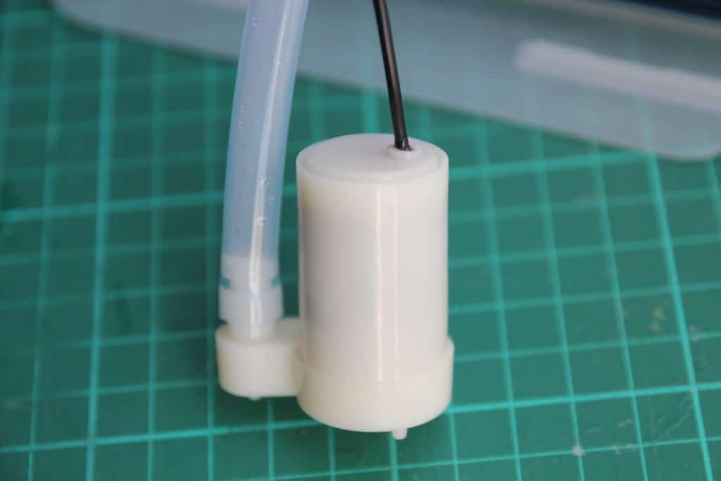
To water the plants, I used a small submersible pump that can be powered with 3.3 V. The pump is controlled with relay 1 of the Arduino MKR Relay Proto Shield. Since the pump only draws around 200 mA, it can be powered directly from the 3.3 V output of the MKR1000.
If you want to use a larger pump, you have to use an external power supply. Make sure that the current rating of the pump is within the specs of the relays.
The black wire of the pump is connected to ground. The red wire goes to the NO (normally open) side of the relay. COM is connected to the 3.3 V output of the MKR1000. Note that this 3.3 V is available at one of the screw terminals of the Proto Shield.
Temperature and humidity sensor
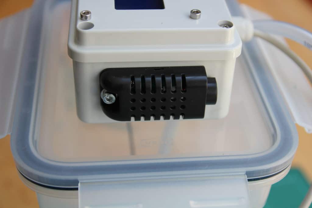
Although not strictly necessary for automatically watering the plants, I thought a temperature and humidity sensor would be a nice addition to the system. For this project, I used an AM2301A sensor which comes in an enclosure with the wires already connected. This sensor is made by ASAIR who also makes the very popular DHT11 and DHT22 sensors.
For more information about DHT temperature and humidity sensors, check out the tutorial below:
Connecting the AM2301A temperature and humidity sensor
The table below shows you which connections you need to make.
| AM2301A temperature and humidity sensor | Arduino MKR1000 |
|---|---|
| Black | GND |
| Red | 3.3 V |
| Yellow | A1 |
I mounted the sensor on the side of the project box. Note that I drilled a small hole in the project box and the back of the sensor to feed the wires through.
I2C LCD
Besides the Arduino IoT Cloud, the sensor data is also displayed on the 20×4 I2C LCD mounted on the lid of the project box.
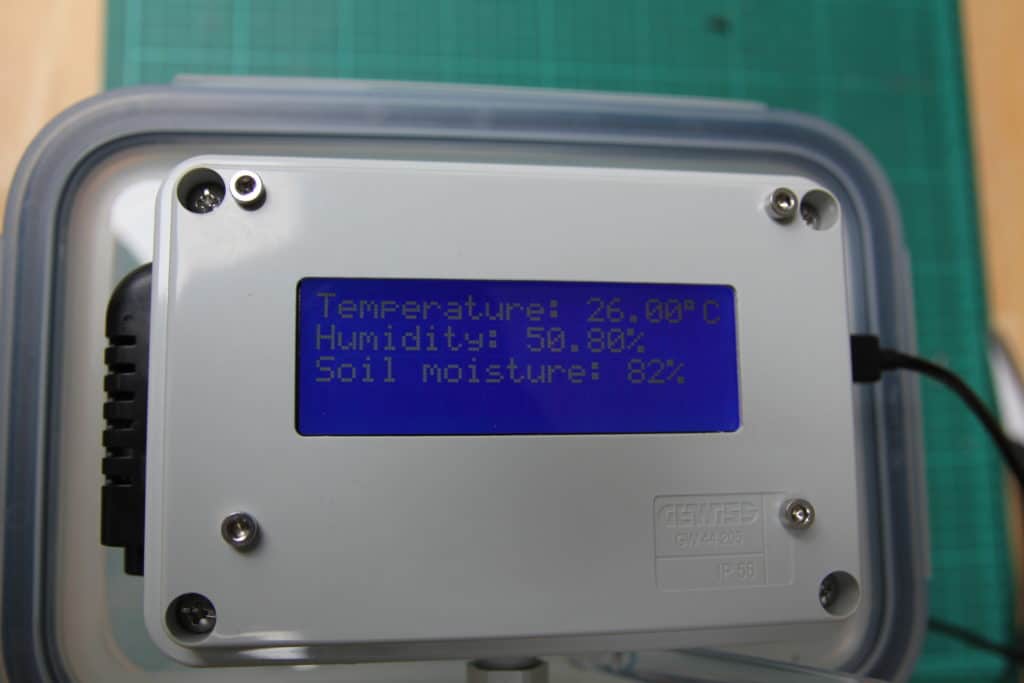
I cut an opening in the project box using my homemade CNC router, but you could use a jigsaw or even a sharp box cutter as well.
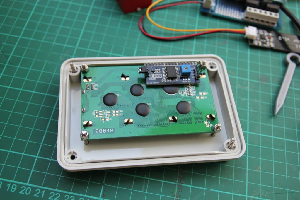
The LCD is usually powered with 5 V but it seems to work fine at 3.3 V. Thanks to the I2C module mounted on the back of the LCD, you only need to connect two wires, SDA and SCL, to the MKR1000. The connections are available at the screw terminals of the shield, so wiring the display is very easy.
I2C LCD connections
| 20×4 character I2C LCD | Arduino MKR1000 |
|---|---|
| GND | GND |
| VCC | 3.3 V |
| SDA | SDA |
| SCL | SCL |
I have written a detailed tutorial on using I2C LCDs with Arduino which you can find here:
A note on wiring
As you might have seen, all of the sensors, the LCD, and the pump need to be connected to 3.3 V and GND. The Arduino MKR Relay Proto Shield only has one power output and shoving all of the wires into one screw terminal is not a good idea. Instead, you can use something like Wago lever nuts as a power distribution point.
The water hose
Initially, I planned to just stick the end of the PVC tube somewhere in the middle of the planter. However, I found that this left part of the planter soaked and the rest completely dry.
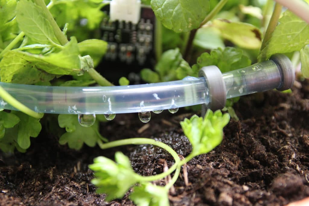
My solution was to drill a bunch of small (1 mm) holes spaced roughly 2 cm apart in the last 30 – 40 cm of the tube. I 3D printed a plug for the end of the tube and some holders to stick in the soil.
You can download the STL files here if you want to print your own:
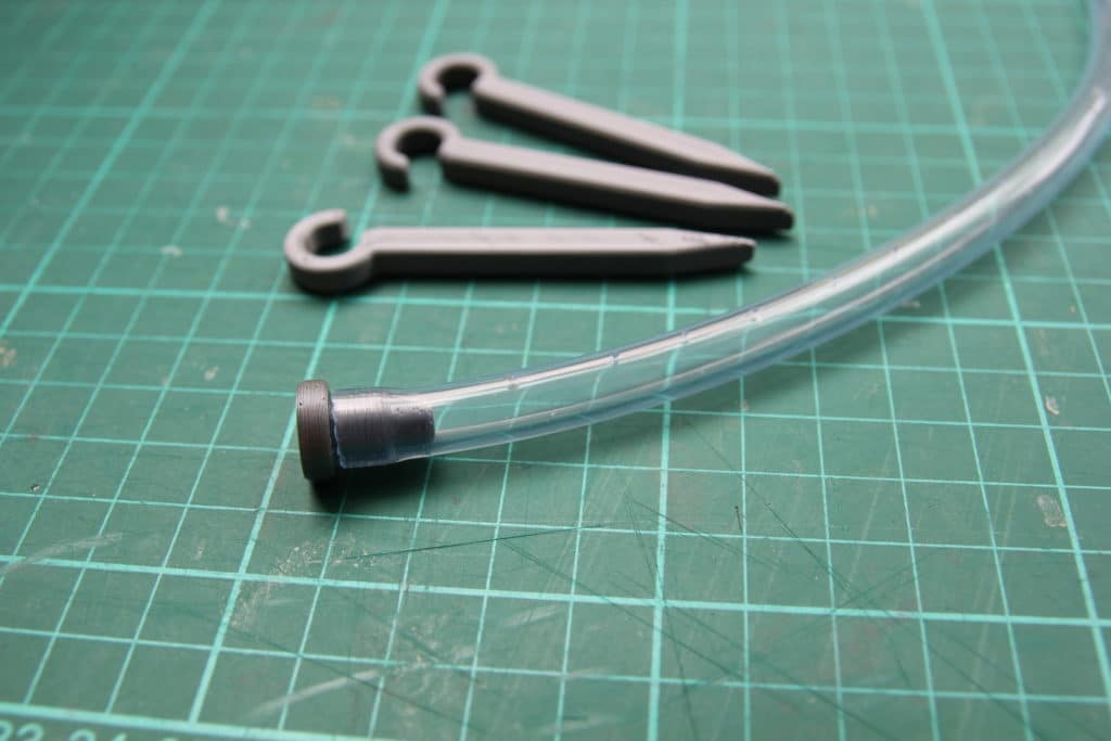
This seems to work quite well to get the soil evenly wet.
Getting started with the Arduino IoT Cloud
In the next section, I will explain how to get started with the Arduino IoT Cloud.
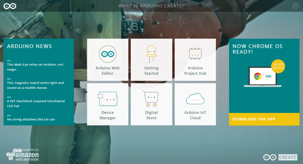
The first step is to go to https://create.arduino.cc/. On this web page you will find the Web Editor, a Getting Started guide, the Device Manager, and a link to the Arduino IoT Cloud.
Installing the Arduino Create plugin
There are multiple ways to set up and configure a new board but I find it easiest to do it via the Getting Started page. Click on the Getting Started icon and scroll to the bottom of the page to where it says Install Arduino Create Plugin. This plugin allows you to upload sketches from the Arduino Web Editor to your board or device.
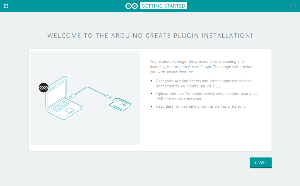
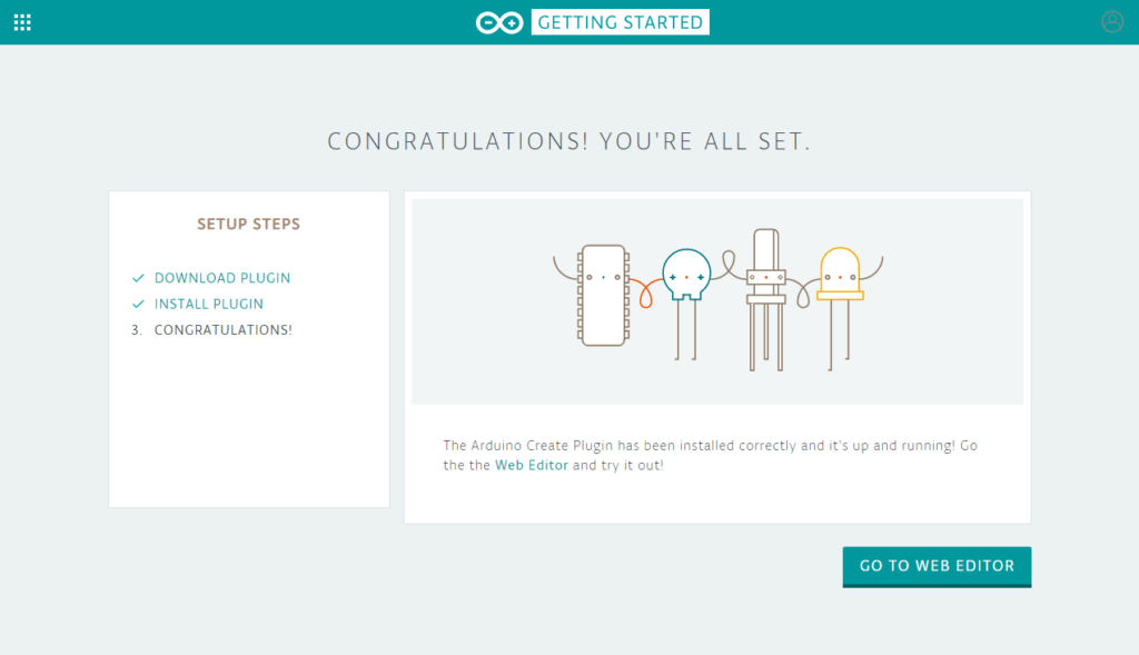
After clicking on the Arduino Create Plugin icon at the bottom of the page, click on start and download and install the plugin. The configuration wizard will check whether or not you have successfully installed the plugin. If you did, you should see the page below.
Setting up an IoT board
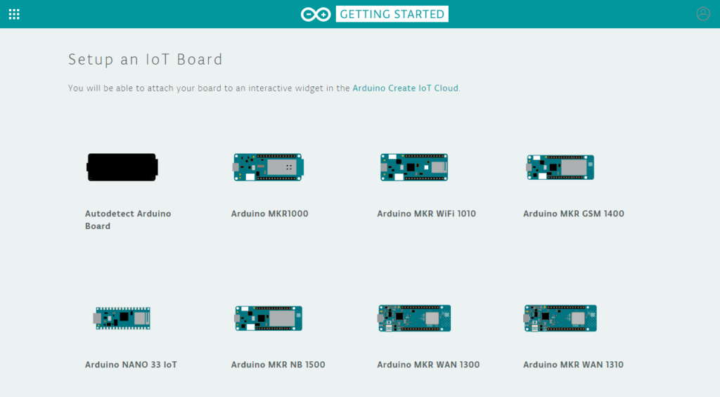
Now go back to the Getting Started page by clicking on the icon at the top of the page. The next step is to set up a new IoT board. For this project, I used the Arduino MKR1000. If you are not sure what the name of your board is, you can click on the Autodetect Arduino Board icon.
The IoT configuration wizard will open which will guide you through setting up and testing the board.
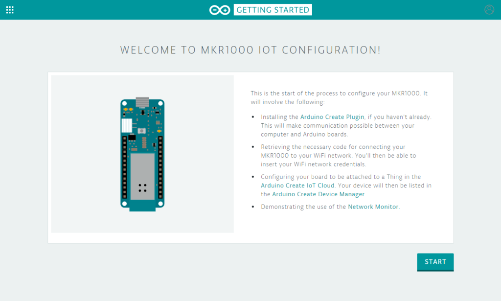
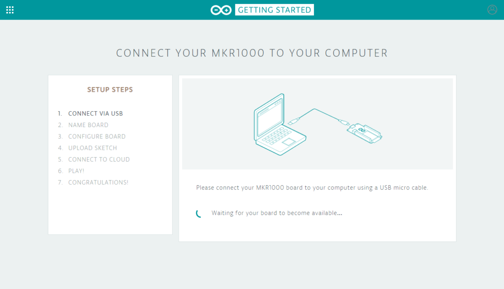
Click on start and connect the board to your computer with a USB cable. If you installed the Arduino Create plugin correctly, the computer should be able to detect your device.
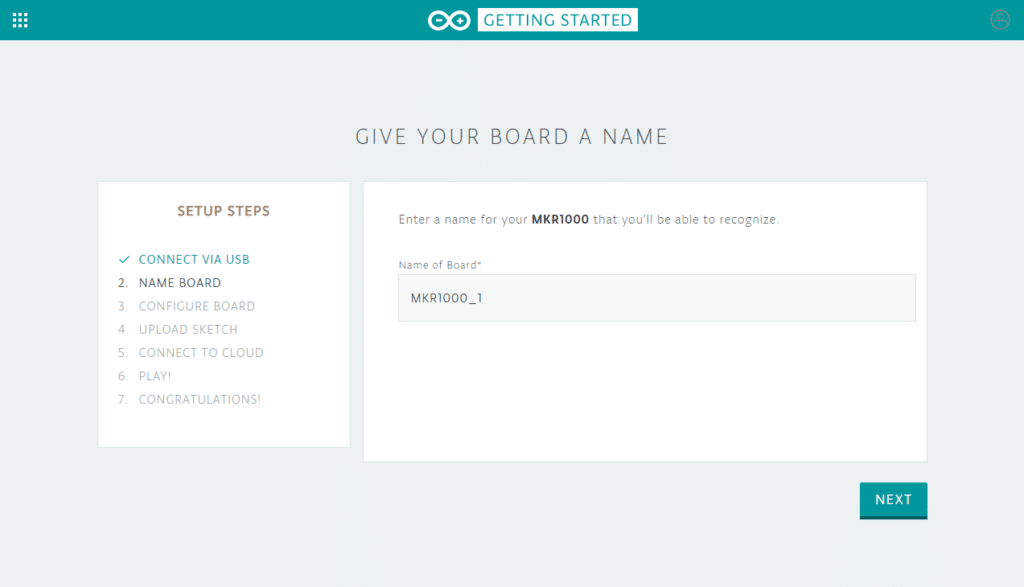
Next, give your board a name. I simply called the board MKR1000_1. Make sure that you use a name that is easy to recognize, especially if you are using multiple boards for different projects.
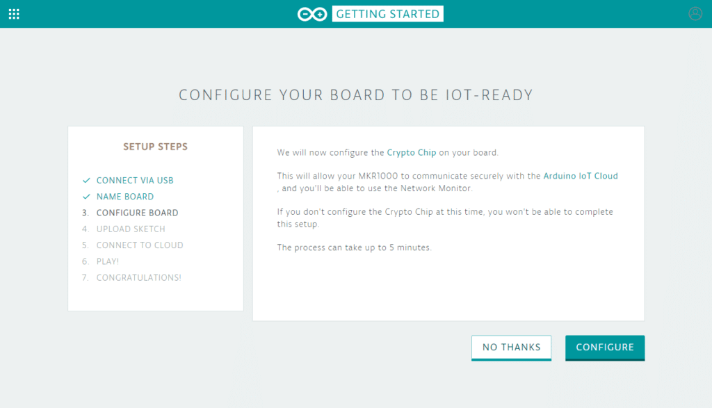
After this, the crypto chip of the MKR1000 needs to be configured which takes up to 5 minutes. Each MKR1000 is equipped with a Microchip ECC508 crypto chip. This chip is used to store the identity of your board securely when it’s linked to your Arduino account.
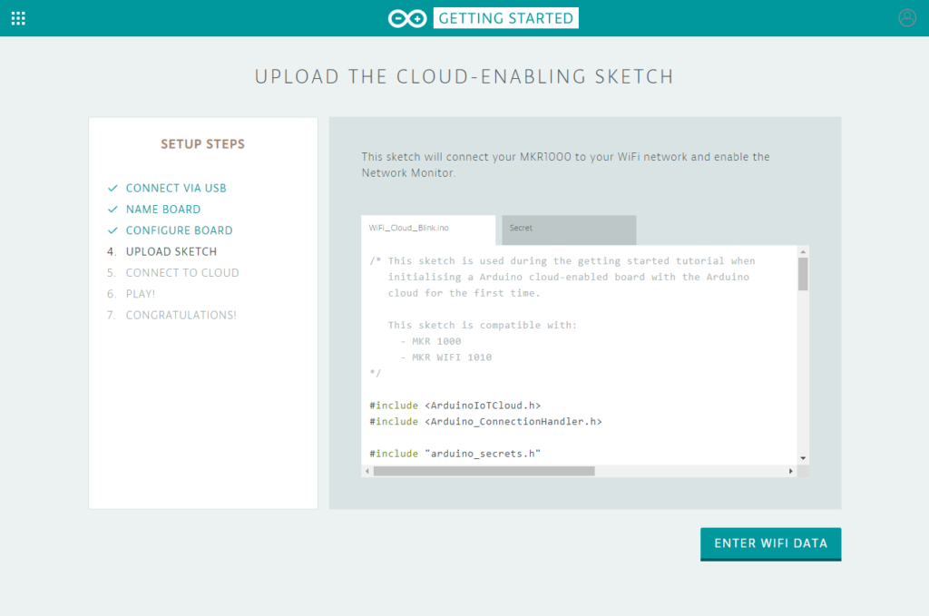
Next, you can upload an example sketch that will allow you to test the functionality of the board and turn the on-board LED on and off via the Network Monitor. In the Secret tab of the sketch, you need to enter the name and password of your local wifi network.
On the next page click on the LED character to turn the on-board LED on and off.
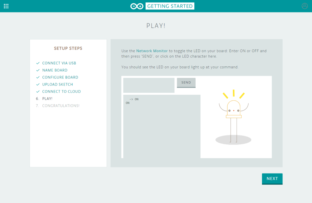
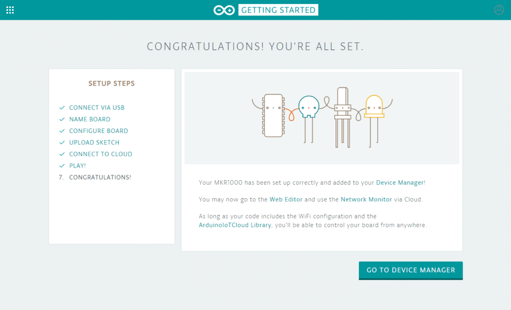
If everything went well, you should see the page below.
Creating a new Thing
After setting up a new IoT device, you can go back to the Arduino Create dashboard and click on the Arduino IoT Cloud icon.
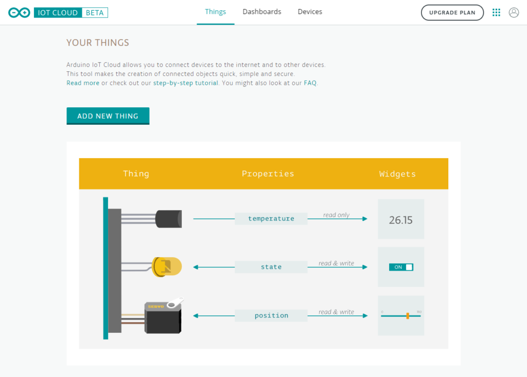
Once you click on this icon, the Arduino IoT Cloud “Your Things” page will open. On this page, you can create new Things, which is what Arduino calls the devices that you can connect to the internet. In our case, the Thing represents the Arduino MKR1000 board with multiple sensors connected. Each thing can have multiple properties like temperature, the state of an LED, GPS coordinates, etc.
In the free version of the IoT cloud, you can create only one Thing with up to five properties. If you want more than one, you have to upgrade to the paid plan for the Arduino cloud. Since this project uses only one Thing with less than five properties, the free-tier works just fine.
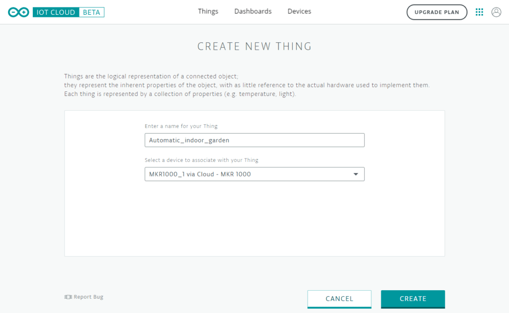
Click on ADD NEW THING and give it a name. I called mine Automatic_indoor_garden. Select the MKR1000 board that we just configured from the dropdown menu (MKR1000_1).
Now you will be redirected to a page where you can add properties to your Thing.
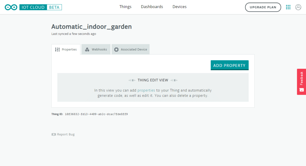
Adding properties
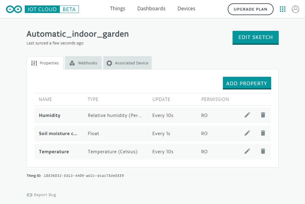
For this project, I added three different properties: temperature, humidity, and soil moisture content. Properties represent variables in the Arduino code and are also readable in the Cloud. After creating the properties and uploading the code, you will be able to see them in your Thing dashboard.
Adding properties is very easy by clicking on ADD PROPERTY. Note that you have to do this process three times.
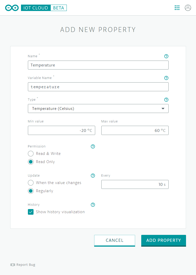
For each property you need to set the following parameters:
- Name – the name that will be displayed on your property list and widget.
- Variable Name – the name of the variable that you will use in your Sketch to reference this property. It can not include special characters.
- Type – select the correct property type. Add the minimum and maximum for numeric measurements, to draw the widget, correctly.
- Permission
- Read & Write: the property can both be set and shown in the Arduino IoT Cloud Dashboard.
- Read Only: the property will be sent to Arduino IoT Cloud and will be available in your Dashboard.
- Update
- When the value changes: The property will be sent to Arduino IoT Cloud every time the value change is greater than or equal to the delta.
- Regularly: the property will be sent to Arduino IoT Cloud each time the specified number of seconds has elapsed.
- History – Shows a visualization of historical data for the property.
In the picture below, you can see which parameters I used for the Temperature property. Note that you can select one of the many built-in property types like Temperature (Celsius) or you can create a custom one.
You can find the parameters for the other properties in the table below
Thing property parameters
| Name | Variable Name | Type | Permission | Update |
|---|---|---|---|---|
| Temperature | temperature | Temperature (Celsius) -20 °C – 60 °C | RO | Every 10s |
| Humidity | humidity | Relative Humidity (Percentage) 0 RH – 100 RH | RO | Every 10s |
| Soil moisture content | soilMoistureContent | Float 0 – 100 | RO | Every 1s |
By selecting show history visualization, you can record the values of your properties during a certain period of time and save them as graphs. Unfortunately, you can only save the data for 1 day in the free version of the Arduino IoT Cloud.
After adding all of the properties click on EDIT SKETCH. This will open the Arduino Web Editor.
Create sketch
After clicking on EDIT SKETCH, you will see that a new sketch has automatically been created.
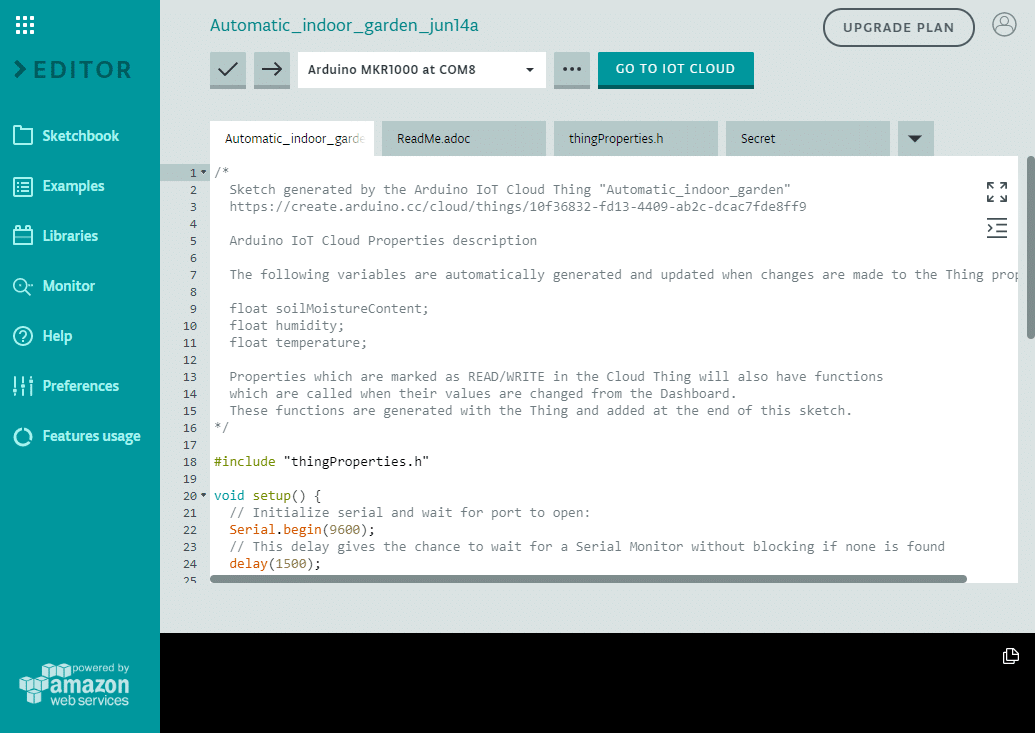
Note that the sketch has the same name as our Thing plus the date of creation. Besides this .ino file, you will see three more files:
ReadMe.adoc: this is a plain text file where you can add information about the author and the project.
thingProperties.h: this file is automatically generated by the Arduino IoT Cloud when you add properties to your Thing. In general, you should not edit the code in this file yourself. It is automatically updated when you change the Thing properties in the dashboard.
Please see the IoT Cloud – Getting Started page on the Arduino Project Hub for a more detailed explanation about the different functions in thingProperties.h.
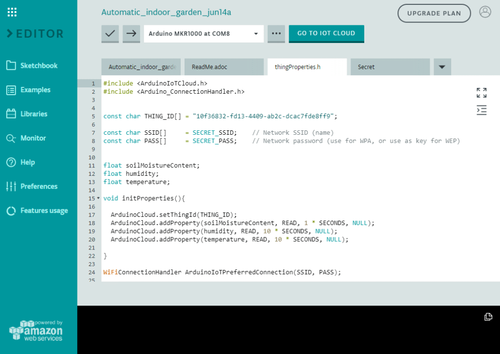
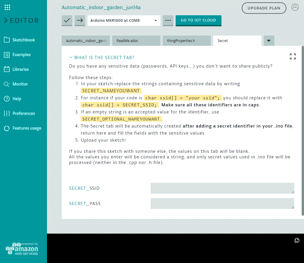
Secret: this tab allows you to fill in your network credentials. SECRET_SSID and SECRET_PASS are the name and password of the wifi network that the MKR1000 will connect to. After filling in these details, click on save.
Arduino code
The auto-generated files make it quite easy to get started with the IoT cloud, but of course, you still need to write some code yourself.
In the main sketch, so not thingProperties.h, I added code that will read out the sensors, controls the water pump, and displays information on the character I2C LCD.
You can replace the code in the main sketch with the code below. Connect the MKR1000 board to your computer if you haven’t already and upload the code by clicking on the upload button (right arrow at the top of the page). I recommend to disconnect the pump for the time being and only leave the sensors installed.
Next, I will explain how the code works and show you how you can change several parameters yourself.
You can copy the code by clicking on the button in the top right corner of the code field.
/*
  Sketch for automatic indoor garden project. More info: https://www.makerguides.com

  Arduino IoT Cloud Properties description

  The following variables are automatically generated and updated when changes are made to the Thing properties

  float soilMoistureContent;
  float humidity;
  float temperature;

  Properties which are marked as READ/WRITE in the Cloud Thing will also have functions
  which are called when their values are changed from the Dashboard.
  These functions are generated with the Thing and added at the end of this sketch.
*/

#include "thingProperties.h"
#include "DHT.h"
#include "LiquidCrystal_I2C.h"

#define DHTPIN A1
#define DHTTYPE DHT21

#define RELAYPIN 1
#define SOILPIN A2

DHT dht = DHT(DHTPIN, DHTTYPE);
LiquidCrystal_I2C lcd = LiquidCrystal_I2C(0x27, 20, 4);

const unsigned long pumpPeriod = 20000;
const unsigned long waitPeriod = 120000;
unsigned long previousMillis;
float moistureSensorData;

void setup() {
  // Initialize serial and wait for port to open:
  Serial.begin(9600);
  // This delay gives the chance to wait for a Serial Monitor without blocking if none is found
  delay(1500);

  // Defined in thingProperties.h
  initProperties();

  // Connect to Arduino IoT Cloud
  ArduinoCloud.begin(ArduinoIoTPreferredConnection);

  /*
     The following function allows you to obtain more information
     related to the state of network and IoT Cloud connection and errors
     the higher number the more granular information you’ll get.
     The default is 0 (only errors).
     Maximum is 4
  */
  setDebugMessageLevel(4);
  ArduinoCloud.printDebugInfo();

  pinMode(LED_BUILTIN, OUTPUT);
  pinMode(RELAYPIN, OUTPUT);

  dht.begin();

  lcd.init();
  lcd.backlight();
}

void loop() {
  ArduinoCloud.update();

  // Your code here
  temperature = dht.readTemperature();
  humidity = dht.readHumidity();

  lcd.setCursor(0, 0);
  lcd.print("Temperature:");
  lcd.setCursor(13, 0);
  lcd.print(temperature);
  lcd.print("\xDf" "C");
  lcd.setCursor(0, 1);
  lcd.print("Humidity:");
  lcd.setCursor(10, 1);
  lcd.print(humidity);
  lcd.print("%");

  moistureSensorData = analogRead(SOILPIN);
  //Serial.println(moistureSensorData);
  soilMoistureContent = map(moistureSensorData, 883, 469, 0, 100);
  soilMoistureContent = constrain(soilMoistureContent, 0, 100);
  lcd.setCursor(0, 2);
  lcd.print("Soil moisture:");
  lcd.setCursor(15, 2);
  lcd.print(soilMoistureContent, 0);
  lcd.print("%  ");

  if (soilMoistureContent <= 30 && millis() - previousMillis >= waitPeriod) {
    digitalWrite(RELAYPIN, HIGH);
    digitalWrite(LED_BUILTIN, HIGH);
    delay(pumpPeriod);
    digitalWrite(RELAYPIN, LOW);
    digitalWrite(LED_BUILTIN, LOW);

    previousMillis = millis();
  }
}
How the code works
In the loop section of the code, the temperature and humidity are read with dht.readTemperature() and dht.readHumidity() respectively. The variables temperature and humidity were added automatically in thingProperties.h and their values will be sent to the cloud every 10 seconds.
The next section of the code prints the values on the I2C LCD.
  lcd.setCursor(0, 0);
  lcd.print("Temperature:");
  lcd.setCursor(13, 0);
  lcd.print(temperature);
  lcd.print("\xDf" "C");
  lcd.setCursor(0, 1);
  lcd.print("Humidity:");
  lcd.setCursor(10, 1);
  lcd.print(humidity);
  lcd.print("%");
Next, the analog output of the soil moisture sensor is read with analogRead(). This value is then scaled to 0 and 100 % humidity. To calibrate the sensor, you can print the sensor data in the Serial Monitor. The value 833 corresponds to the value I got when I held the sensor in the air and 469 when I stuck it in a glass of water.
  moistureSensorData = analogRead(SOILPIN);
  //Serial.println(moistureSensorData);
  soilMoistureContent = map(moistureSensorData, 883, 469, 0, 100);
  soilMoistureContent = constrain(soilMoistureContent, 0, 100);
  lcd.setCursor(0, 2);
  lcd.print("Soil moisture:");
  lcd.setCursor(15, 2);
  lcd.print(soilMoistureContent, 0);
  lcd.print("%  ");
In the last section of the code, I check if the soil moisture content is below 30 % and if so, the plants are watered for a set duration. I added a minimum wait period between watering cycles to give the soil some time to absorb the water.
  if (soilMoistureContent <= 30 && millis() - previousMillis >= waitPeriod) {
    digitalWrite(RELAYPIN, HIGH);
    digitalWrite(LED_BUILTIN, HIGH);
    delay(pumpPeriod);
    digitalWrite(RELAYPIN, LOW);
    digitalWrite(LED_BUILTIN, LOW);

    previousMillis = millis();
  }
You will probably have to tweak the parameters pumpPeriod and waitPeriod at the top of the code to suit your particular setup.
Create a dashboard
After uploading the code, click on GO TO IOT CLOUD. Now click on Dashboards at the top of the page.

When you are on this page, click on create dashboard. You can add widgets to your dashboard to display values, charts, etc.
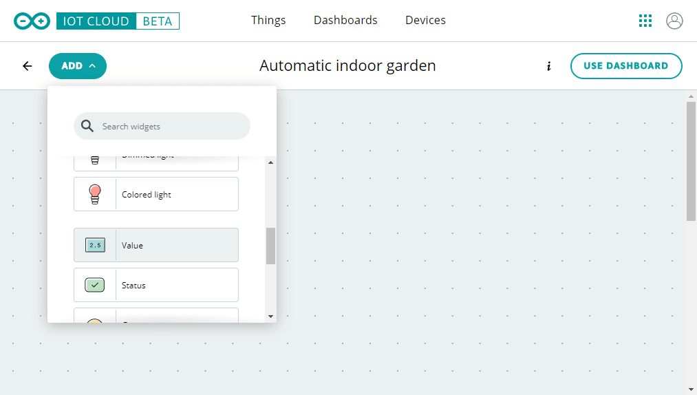
Click on the widget and select Link Property
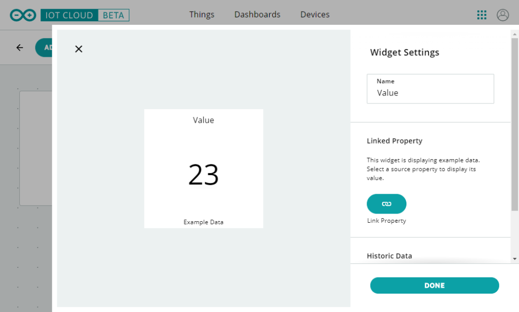
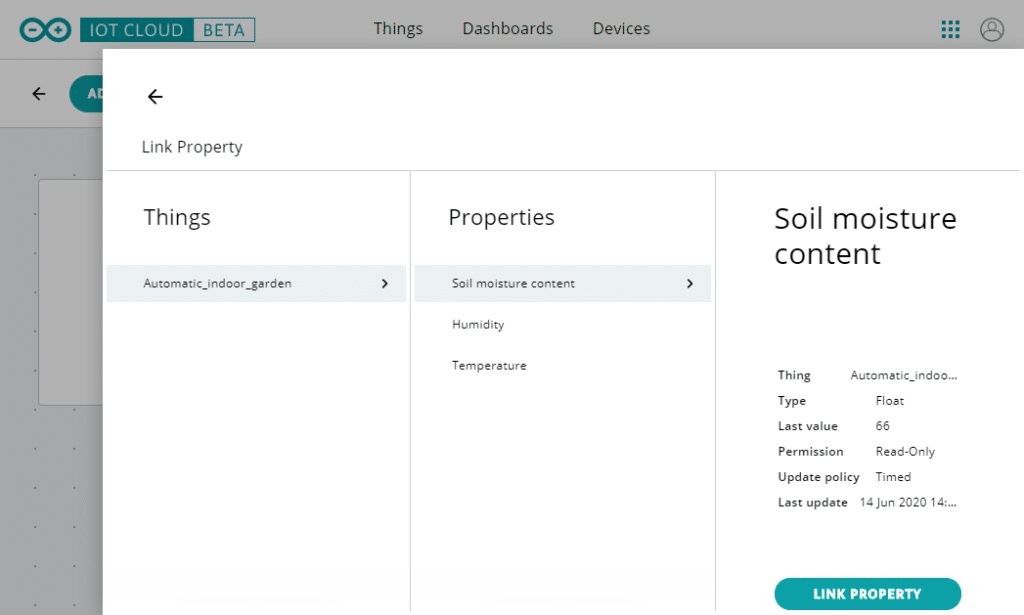
Now select which property you want to display.
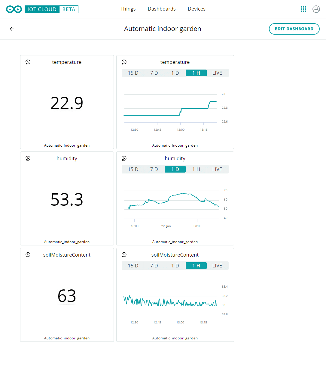
After adding multiple widgets, your dashboard should look something like this:
Wrapping up
In this article, I have shown you how you can create a simple automatic watering system with the MKR1000 and the Arduino IoT Cloud. I hope this tutorial was helpful and can give you some inspiration.
In the current setup, the Arduino IoT Cloud is only used to display and record the sensor data. Hence, you could also make this as a standalone system with an Arduino Uno or similar. Personally, I just wanted to experiment with the Arduino IoT Cloud and see how difficult it was to set up. It was quite a bit easier than I thought and I will definitely use it for other projects in the future.
I have been running this system for a short while and it seems to be working great. I will report back in a month or so, once I have tested it for a bit longer.
One thing I might add in the future is a water level switch for the tank and connect it to an email alert system. I’m afraid I will forget to refill the tank now that I don’t have to think about watering the plants anymore…
If you have any questions or suggestions, please leave a comment below.
Note that comments are held for moderation to prevent spam.

This work is licensed under a Creative Commons Attribution-NonCommercial-ShareAlike 4.0 International License.
Other Useful Links From Around The Web:
Benne is professional Systems Engineer with a deep expertise in Arduino and a passion for DIY projects.
Chanel Tolksdorf
Monday 16th of May 2022
Hi, i am working on a project for my engineering class and this has been such a huge help. A question I had was would we still get the relay proto shield with a nano or how would we connect that otherwise. Thanks!
nicola pivetta
Monday 15th of March 2021
Hello, I'm Nicola. Thanks so much for sharing so much in detail your project. It is a delight. I'm working in this moment at a project () where I use the "IOT Arduino cloud" like you and I got a nema 17 stepper motor with L298n that is going to open the doors of a greenhouse when temperature and humidity has some conditions. But I have a problem. I can run the step motor with the sample code when is not in a the "arduino IOT cloud" but If I copy and paste the conde in the "arduino IOT cloud" enviroment the stepper motor is not working anymore. From your posts I can see that you have experience with IO cloud and steeper motors, so I belive that you did domething similar or not to far. If you wan to to see the code I have it in the link, in the arduino project hub. Thanks in advance. Nicola
Frank
Friday 5th of March 2021
Do you have any recommendations for how to make a new cable for the moisture sensor? Did you create yours from some other cable that you salvaged or did you pull/crimp/heat-shrink it yourself?
Benne de Bakker
Sunday 14th of March 2021
Hi Frank,
Yes, I made the new cable myself. You can buy assortment boxes with the connector housings and crimp pieces on AliExpress or Amazon. Unfortunately, I don't remember which exact type they are.
Benne
Anthony Denaro
Monday 28th of September 2020
Hi Benne,
I am working on an art project and was hoping you could lend your expertiece with some input.
I am creating a canvas (12 x 24 as a trial) and on the back, I want to build a full direcetional (up, down, left, right, horizontal) pulley system, similar to what you would find on a 3D printer I guess. I would like the system to do a few things:
First, it's purpose is to move a magnet around on a random course at random times that will be on the painted side of the canvas. The magent will be held in place by another magent that is part of the pulley system on the back of the canvas.
Second, I would like to add a motion sensor, so that not only is the system random movement to random locations, but will turn on if it senses movement in front of the canvas.
Third, I would like the speed of movement to also be random, from almost can't see movement, to something that is noticeably moving.
I am new to all this, and was excited to come across your site.
I hope to hear from you with any ideas or input.
Regards,
Anthony
Admon
Friday 25th of September 2020
Great idea! However this type of installation (transparent plastic pipe and container) looks good on pictures only. In reality algae appear on an inner/wet side in one week time.
Benne de Bakker
Sunday 27th of September 2020
Good point! This system works fine as a proof of concept but an opaque container and tube would definitely be better in the long run.