You can find linear actuators everywhere. They are found in industries, homes, offices, shopping malls and more. The devices have applications in window automation, safety door locks, robotics, solar panel controller, agriculture machinery, and much more.
Linear actuators are easy to use. There are several linear actuators, but the basic operation principle is similar. Linear actuators convert the electrical power into linear mechanical movement with the help of a motor and a pair of switches.
In this article, I will take you through the basic operation principles of linear actuators, how to build a linear actuator driver, and how to use linear actuators with Arduino devices.
I’ve included a linear actuator interface diagram, example code, and answered some common questions that people often have.
By the end of this article, you will be confident in working with Arduino and linear actuators.
Let’s get started.
Components Needed To Complete Arduino-based Linear Actuator Project
Hardware Components
- Arduino Uno Rev3 x 1
- Linear Actuator x 1
- Dupont wire 1 set
- Arduino USB cable x 1
- DC power supply x 1
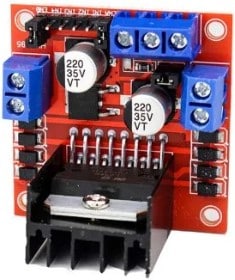
- L298N driver board x 1
Software
Makerguides.com is a participant in the Amazon Services LLC Associates Program, an affiliate advertising program designed to provide a means for sites to earn advertising fees by advertising and linking to products on Amazon.com.
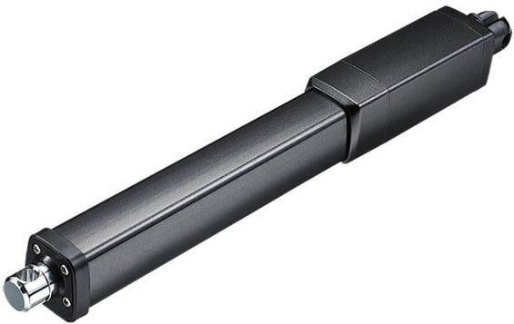
What Is A Linear Actuator?
A Linear Actuator is an electromechanical device that converts circulatory motion into a linear motion. It consists of a motor, limit switches, gears, a lead screw, and a cylinder. The linear actuators come in various sizes and shapes depending on the intended applications.
In the following sections, I will take you through the working principle of a linear actuator and the different types of linear actuators available.
How does a linear actuator work?
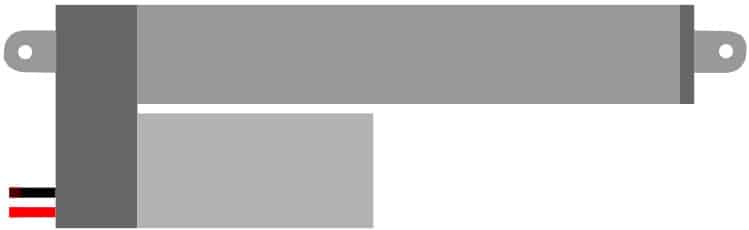
Here is a mechanical drawing of a lead screw type linear actuator.
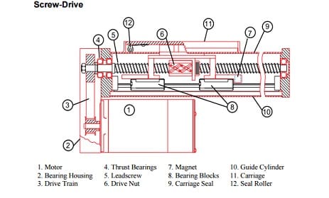
I have listed the critical parts of the linear actuators and their functions.
Motor – a DC motor is the heart of the linear actuator. The motor connects to the different parts of the actuators, which finally bring the linear motion.
Lead Screw – The lead screw converts the rotary motion of the Dc motor into linear motion. I can give you a simple analogy. Think of a screwdriver sending a nail inside the wooden block. In this example, the screwdriver is rotated by a user in a circular fashion where s the screw moves linearly.
Gears – The gears are one of the best inventions and my favorite machine. The gears convert the low torque high-speed motor energy into low-speed high torque energy, which can be used to drive the leadscrew.
The arrangement of gears will define the maximum power the linear actuator can handle and the speed.
Types of linear actuators
You can find various types of actuators based on space constraints and specific applications. All the images below are attributed to www.timotion.com.
Parallel Drive Actuator Type
The driving motor will be parallel to the spindle. These type of actuators are found everywhere.
The actuators can provide a range of loads and linear motion.
L type or a Right Angle Actuator Type
As the name suggests, the motor will parallel the driving spindle. Typical gears used are worn gear styles. The worm gear mechanism produces significantly less noise.
The actuators can self-lock due to the gear mechanics, which is a prime advantage.
Inline Actuator Type
The motor and the spindle will be inline in these linear actuators. You can mount these in narrow spaces.
These are known to generate higher noise compared to L-type actuators.
Dual Motor Actuator Type
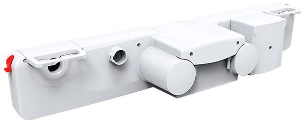
These actuators consist of two motors which you can drive separately or synchronously. The applications include a hospital bed driving mechanism, windows, and more.
There are several other types of actuators that you can find, such as vertical sliders ( for hidden cabinets in the kitchen, floor, etc.), linear slide actuators, etc.
In the next section, let us see the list of parameters we should look at while selecting a linear actuator.
- Load drive strength
- Space available for mounting
- Amount of sound the actuator makes
- Speed of operation etc.
Here is a screenshot from a linear actuator found on digikey.
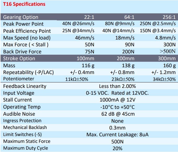
Here are a few takeaways from the datasheet
- As the gear ratio increases, the max speed decreases.
- All actuators will have a peak power point. This is where the power delivery will be maximum at a given speed and force. You will save power and get maximum efficiency if you operate the device at this speed with the specified load.
- Actuators should be operated within their specified duty cycle. A duty cycle of 20% means you should drive the actuator for not more than 20% of the time. For example, if you operate the actuator for one minute. You should not run the actuator for another 4 minutes
- The force is proportional to the gear ratio
Driving a Linear Actuator
You must use a DC motor driver to drive the linear actuators. The H bridge motor driver boards are designed to control the DC motors of the linear actuators.
The H bridge is necessary because you need to control the linear actuator in both forward and reverse directions (push and pull).
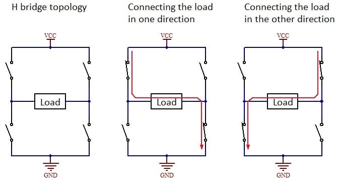
Depending on the type of H bridge driver you have, you need to plan the driving strategy. You will need two GPIOs to control the motor in two directions but you can use any of the GPIOs. We will use a PWM signal on the GPIO to control the speed of the linear actuator.
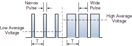
The duty cycle of the PWM signal will be proportional to the speed of the linear actuator. The PWM can vary from 0 to 255 (0 V to 5 V), corresponding to no movement to the maximum speed possible.
There are several DC motor driver boards you can find online.
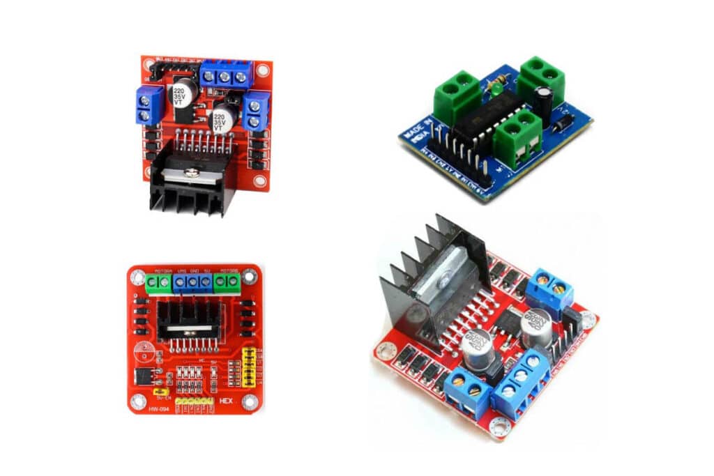
Though they vary in colors, size, or options, the basic principle of operation remains the same.
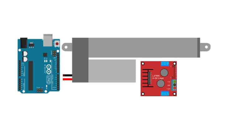
Step-By-Step Instructions To Connect A Linear Actuator Valve To An Arduino
In this section, I will take you through the steps to build a simple Arduino base linear actuator project. Let’s start!
How To Connect Linear Actuator to An Arduino?
Here are the connection details needed to complete the linear actuator and the Arduino UNO board.
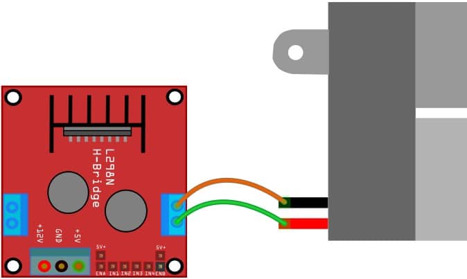
I am using Arduino UNO for this example, along with the H bridge driver in between Arduino UNO and the actuator.
Step 1: Start with the Linear Actuator
The linear actuator consists of two wires. Positive and negative. Simply reversing the voltages applied across the two wires will change the direction of the motion.
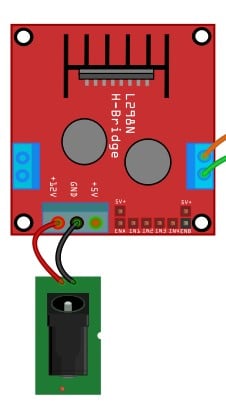
Step 2: Connect the linear actuators’ terminals
The red wire and black wires are interchangeable. The board I am showing has two connectors (for two linear actuators). We are using only one in this demonstration.
Step 3: Connect the Power supply to the H Bridge driver
Make sure you match the DC voltage to the actuator’s rating from the datasheet.
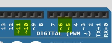
Step 4: Connect the Arduino GPIO pins to the H bridge controller IC
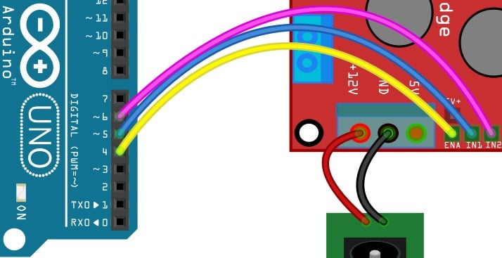
The pins selections are arbitrary. If you select the PWM compatible pins, the PWM generation will be hardware timer based.
If the pins have a “~” symbol behind the PIN, it means that they are PWM compatible.
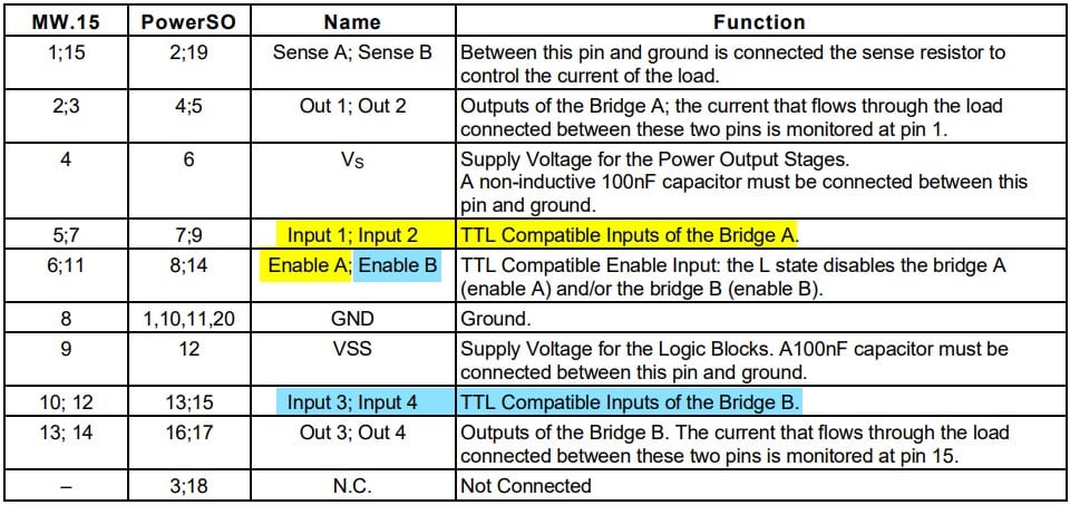
The Input 1 and Input 2 pins corresponds to bridge A. You can see the pinout of the L298N in the table below.
Step 5: The Entire connection
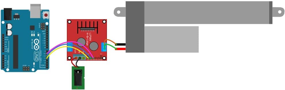
You can verify the connection once more to be sure of the connection.
Congratulations! You have now completed the connections as well as a fair understanding of linear actuators.
The following section shows you the basic Arduino code required to test the circuit.
Arduino Code For the Linear Actuator And The Arduino Uno Project
Here is a simple Arduino sketch you can use to program the Arduino. The author has mapped the control pins in the code below to pins 10 and 11. Both 10 and 11 are PWM compatible. In our connections above, we connected the input pins of the H bridge driver to pins 4 and 5.
Some linear actuators will provide you feedback on the position, you can adapt the code based on that.
#include "elapsedMillis.h"

elapsedMillis timeElapsed;

int RPWM = 10;
int LPWM = 11;
int sensorPin = A0;

int sensorVal;
int Speed = 255;
float strokeLength = 6.0;
float extensionLength;

int maxAnalogReading;
int minAnalogReading;

void setup() {
  pinMode(RPWM, OUTPUT);
  pinMode(LPWM, OUTPUT);
  pinMode(sensorPin, INPUT);
  Serial.begin(9600);
  maxAnalogReading = moveToLimit(1);
  minAnalogReading = moveToLimit(-1);
}

void loop() {
  Serial.println("Extending...");
  sensorVal = analogRead(sensorPin);
  while (sensorVal < maxAnalogReading) {
    driveActuator(1, Speed);
    displayOutput();
    delay(20);
  }
  driveActuator(0, Speed);
  delay(1000);

  Serial.println("Retracting...");
  sensorVal = analogRead(sensorPin);
  while (sensorVal > minAnalogReading) {
    driveActuator(-1, Speed);
    displayOutput();
    delay(20);
  }
  driveActuator(0, Speed);
  delay(1000);
}

int moveToLimit(int Direction) {
  int prevReading = 0;
  int currReading = 0;
  do {
    prevReading = currReading;
    driveActuator(Direction, Speed);
    timeElapsed = 0;
    while (timeElapsed < 200) { delay(1); }
    currReading = analogRead(sensorPin);
  } while (prevReading != currReading);
  return currReading;
}

float mapfloat(float x, float inputMin, float inputMax, float outputMin, float outputMax) {
  return (x - inputMin) * (outputMax - outputMin) / (inputMax - inputMin) + outputMin;
}

void displayOutput() {
  sensorVal = analogRead(sensorPin);
  extensionLength = mapfloat(sensorVal, float(minAnalogReading), float(maxAnalogReading), 0.0, strokeLength);
  Serial.print("Analog Reading: ");
  Serial.print(sensorVal);
  Serial.print("\tActuator extension length: ");
  Serial.print(extensionLength);
  Serial.println(" inches");
}

void driveActuator(int Direction, int Speed) {
  switch (Direction) {
    case 1:  //extension
      analogWrite(RPWM, Speed);
      analogWrite(LPWM, 0);
      break;

    case 0:  //stopping
      analogWrite(RPWM, 0);
      analogWrite(LPWM, 0);
      break;

    case -1:  //retraction
      analogWrite(RPWM, 0);
      analogWrite(LPWM, Speed);
      break;
  }
}
FAQ’s About The Linear Actuator And Arduino UNO Project
I have compiled the most frequently asked questions about the Arduino UNO and linear actuator projects.
If you have further questions about the linear actuators, please post the questions in the comments window.
1) Can Arduino control a linear actuator?
Arduino can control a linear actuator. Arduino cannot drive the linear actuator directly. The current and the voltage requirements are beyond the Arduino UNO capabilities.
What you can do is this. It would help if you used an H bridge IC or an H bridge driver board to drive the actuator. It would be best if you also had an external power supply.
You must use the H bridge circuit to drive the motor in both directions.
2) How do you control the speed of a linear actuator in Arduino?
You can control the speed of the linear actuator by modulating the motor speed. You can use a PWM signal from the Arduino UNO to maintain the motor’s speed.
PWM is a standard technique for varying the duty cycle to control the motor’s speed.
In some linear actuators, you will also get feedback on the position of the moving arm.
You can use the position and time information to control the speed of the linear actuator.
3) How do you control 4 linear actuators?
One L298D IC can drive two linear actuators. Two control four linear actuators. You can use two such boards.
Watch out for the total current consumption.
The total current consumed by both linear actuators should be less than the current capability of the L298N.
4) How do you program a linear actuator?
Programming a linear actuator is similar to programming a DC motor. It would help if you used an external driver (L298D) to supply sufficient power to the linear actuator.
The direction and speed is easily controlled by the GPIO pins of the Arduino UNO.
You can refer to the article above for connection details and project examples.
Conclusion
In this article, I have presented the basic working principle of a linear actuator along with the different types of actuators available.
I am positive that you have enough information to build your next linear actuator project confidently.
I will be glad to hear about the projects you have created using linear actuators.
You can share your projects in the comments.
Please post your queries in the comments section. I will be happy to answer and provide more support if needed.
I would be glad to hear your feedback on the article. Please share your feedback along with suggestions to improve the presentation.
Don’t forget to share the report with your friends and other Arduino enthusiasts!

I am Puneeth. I love tinkering with open-source projects, Arduino, ESP32, Pi and more. I have worked with many different Arduino boards and currently I am exploring, Arduino powered LoRa, Power line communication and IoT.