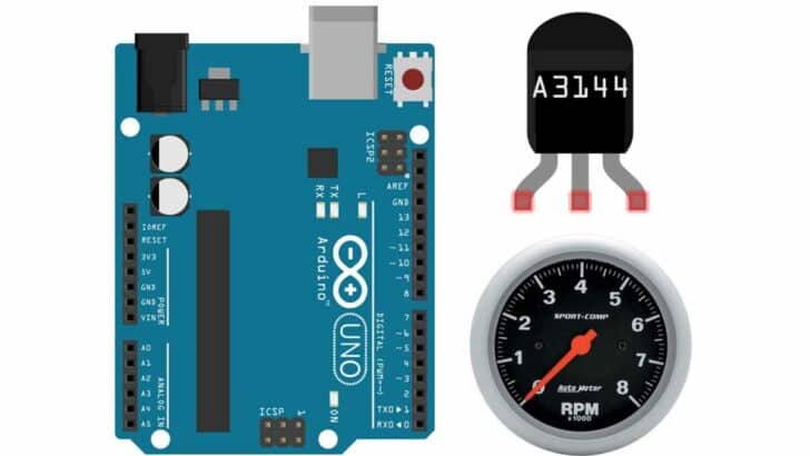
In this tutorial you will learn how to use the A3144 Hall Effect Sensor and an Arduino to build a Tachometer. A tachometer is a device to measure the speed of a rotating object. For instance, it is common in automotive applications to monitor the RPM (revolutions per minute) of an engine.
The Hall Effect sensor detects the presence of a magnetic field. By attaching a small magnet to a rotating object, we can use this to count revolutions. With an Arduino we then can measure the time it took for a given number of revolutions and calculate the RPM.
In the next sections, I will list the required parts for this project, explain the basics of Hall Effect sensors, and introduce the A3144 Hall Effect sensor, which we will be using for our tachometer. I will also provide examples of different tachometer implementations using the A3144 sensor, including a simple tachometer and a more advanced one using interrupts.
So let’s get started!
Required Parts
Makerguides.com is a participant in the Amazon Services LLC Associates Program, an affiliate advertising program designed to provide a means for sites to earn advertising fees by advertising and linking to products on Amazon.com. As an Amazon Associate we earn from qualifying purchases.
Below you will find the parts required for this project. If you just want to explore and learn about Hall Effect Sensors buy the Sensor Module. It will be a bit easier to use but is too big for practical applications. For those rather buy the Hall Effect Sensor itself, which is much smaller and cheaper as well.

Arduino Uno

USB Cable for Arduino UNO

Dupont Wire Set

Resistor & LED kit
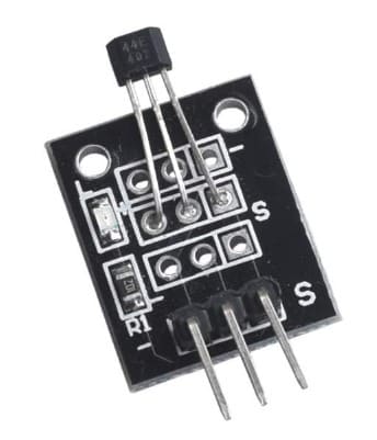
A3144 Hall Effect Sensor Module
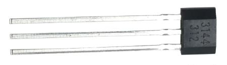
A3144 Hall Effect Sensor

Magnets
Basics of Hall Effect Sensors
Hall Effect sensors are electronic devices that can detect the presence of a magnetic field. They work based on the Hall Effect, which is the creation of a voltage difference across a conductor when it is placed in a magnetic field while current flows through it.
How do they work?
Hall Effect sensors consist of three main components: a voltage source, a current-carrying conductor, and a magnetic field. When a magnetic field is applied perpendicular to the current flow in the conductor, it creates a Lorentz force that pushes the electrons to one side of the conductor. This creates a voltage difference across the conductor, which can be measured.

Typical applications
Typical application for Hall Effect sensors are:
- Proximity sensing: Hall Effect sensors can detect the presence or absence of a magnetic field, making them suitable for proximity sensing applications.
- Speed measurement: By attaching a magnet to a rotating object and using a Hall Effect sensor to detect the magnetic field changes, the speed of the object can be measured.
- Current sensing: Hall Effect sensors can measure the current flowing through a conductor by detecting the magnetic field generated by the current.
- Position sensing: By placing magnets at specific positions and using Hall Effect sensors, the position of an object can be determined.
Latching vs non-latching
Hall Effect sensors can be categorized as latching or non-latching. Latching sensors have a built-in magnetic field that keeps them in the on or off state until another magnetic field of opposite polarity is applied. Non-latching sensors, on the other hand, only detect the presence of a magnetic field and do not retain their state. We will be using a non-latching sensor.
Bipolar vs unipolar
Hall Effect sensors can also be classified as bipolar or unipolar. Bipolar sensors can detect both positive and negative magnetic fields, while unipolar sensors only respond to one polarity. The A3144 Hall Effect Sensor is a unipolar sensor and will react only to one pole of a magnet.
Switching vs linear
Hall Effect sensors can operate in either switching or linear mode. Switching sensors provide a digital output, toggling between on and off states based on the presence or absence of a magnetic field. Linear sensors, on the other hand, provide an analog output that varies linearly with the strength of the magnetic field. We will be using the A3144 Hall Effect Sensor, which is of the switching type.
Hall Effect Sensors vs Reed Relays
Apart from the Hall Effect Sensor another common type of magnetic switch is the Reed Relay. Let’s quickly discuss the differences between them.
Hall Effect Sensors offer advantages such as non-contact sensing, solid-state technology, faster response time, wide operating temperature range, and digital output. However, they have a limited sensing range, higher cost, and are sensitive to stray magnetic fields.
Reed relays, on the other had, have a wide sensing range, lower cost, and are insensitive to stray magnetic fields. However, they suffer from mechanical wear and tear, slower response time, and limited operating temperature range. For more detailed information have a look at our tutorial on Interfacing Magnetic Switch To The Arduino.
In the next section, we will have a look at the A3144 Hall Effect sensor and its features.
Introducing the A3144 Hall Effect Sensor
The A3144 Hall Effect Sensor is a fantastic, very small magnetic sensor packed with electronics.
It can operate with unregulated voltages from 4.5 up to 24 Volts due to a built-in voltage regulator. In addition it has reverse polarity protection, which means if you wire it wrongly it will survive. The power consumption with 3.5mA (at 5V) is minimal, making it a suitable for battery-powered applications.
The image below shows you the pinout. If you look at the sensor from the front where you can read the label, the positive pin (+) will be to the left. Ground (-) is in the middle and the signal output (s) is the right pin.
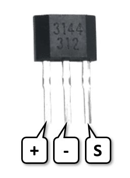
Note that the A3144 is unipolar. So it will react to only one pole of a magnet but not the other. Remember this when testing it!
The sensor has an open-collector output, which means it can be directly interfaced with microcontrollers and can drive up to 25mA. We will take advantage of that and directly connect an LED to test its function.
Finally, the A3144 sensor has a high sensitivity (2.5mV/Gauss), a high operating frequency of 2kHz and a wide operating temperature range of -40°C to +150°C. In short, it is a great sensor for almost any application that requires frequent, contactless, fast switching.
Testing the A3144 Hall Effect Sensor
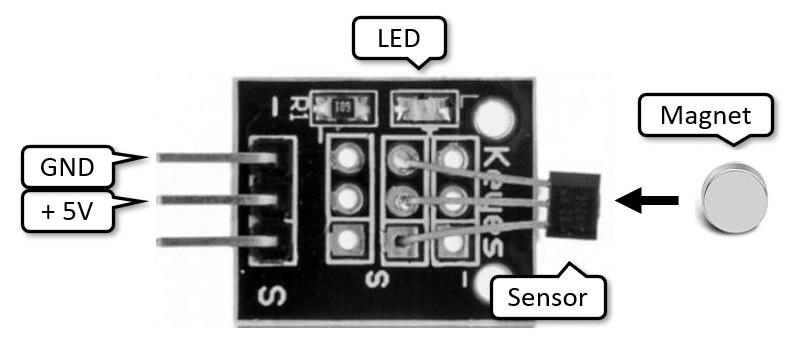
As mentioned under required parts, you can buy the sensor as a module or the plain sensor itself. The module has an integrated LED and pullup resistor (R1) and is therefore very easy to test. Just connect 5V (up 24V) to the module and bring the magnet close to the sensor. The LED should light up. But remember that the sensor is unipolar. Try both poles of the magnet. One side will work the other will not.
If you want to test the plain sensor, you will need to wire up an LED and a pullup resistor yourself. The schematic below shows you how to do this.
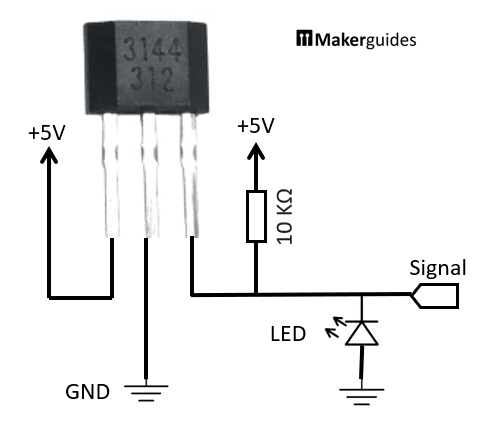
Note that the logic is inverted. The LED will glow weakly (due to the 10 KΩ resistor) and will switch off when the magnet gets near the sensor. Remember this behaviour for later. In short, the output of the A3144 will go low when the a magnetic field is detected and is otherwise high.
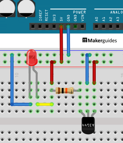
By the way: If you want to test this on a breadboard using the Arduino power supply; here is the wiring. Don’t forget the 10 KΩ pullup resistor.
In the next section, I show you how to connect the A3144 Sensor properly to the Arduino.
Connecting the A3144 Hall Effect Sensor
Most of the necessary wiring you have seen already above. The only difference will be that we will connect the output of the A3144 Sensor to Pin 2 of the Arduino.
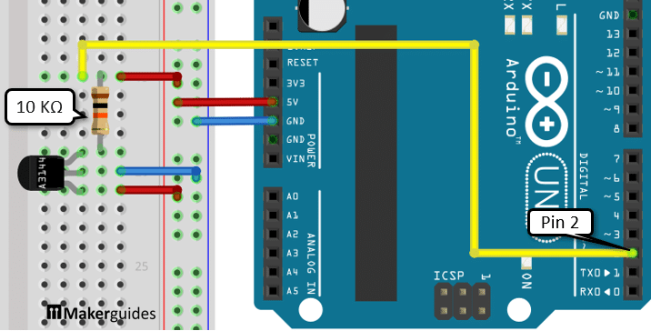
To summarize, we connect power from the Arduino to the breadboard and from there to the A3144 Sensor. Then we add the 10 KΩ pullup resistor and connect the output of the A3144 to Pin 2 of the Arduino. If you have any issues; below is the complete wiring table.
| From | Pin | Wire color | To | Pin |
| Arduino | 5V | Rojo | Tablero de pruebas | Positive rail |
| Arduino | GND | Blue | Tablero de pruebas | Negative rail |
| A3144 | GND | Blue | Tablero de pruebas | Negative rail |
| A3144 | VCC | Rojo | Tablero de pruebas | Positive rail |
| A3144 | Out/Signal | Amarillo | Arduino | 2 |
| A3144 | Out/Signal | - | Resistencia | 1 |
| Resistencia | 2 | Rojo | Tablero de pruebas | Positive rail |
In the next section I will show you, how to use the A3144 as a simple magnetic switch.
Example 1: A Magnetic Switch
Have a quick look at the very simple code below. Every 10ms we read the sensor value and if its value is LOW we switch the built-in LED of the Arduino on. If you bring a magnet close to the sensor, the LED should light up.
const int hallPin = 2;
const int ledPin = 13;  // built-in

void setup() {
  pinMode(hallPin, INPUT);
  pinMode(ledPin, OUTPUT);
}

void loop() {
  int val = digitalRead(hallPin);
  digitalWrite(ledPin, val ? LOW : HIGH);
  delay(10);
}
Here a detailed explanation of the code.
Constants and Variables
The code begins by defining two constants: hallPin y ledPin. El hallPin constant specifies the pin to which the Hall Effect sensor is connected, and the ledPin constant the pin for the built-in LED on the Arduino board.
const int hallPin = 2;
const int ledPin = 13;  // built-in
Setup function
En el setup() function, we set the mode of hallPin to INPUT and the mode of ledPin to OUTPUT. This is done using the pinMode() función.
void setup() {
  pinMode(hallPin, INPUT);
  pinMode(ledPin, OUTPUT);
}
Loop function
Inside the loop() function, we first read the value of the hallPin using the digitalRead() function. The value read from the pin will be LOW when a magnetic field is detected and HIGH otherwise. Watch out for this inverted logic.
int val = digitalRead(hallPin);
Next, we use the digitalWrite() function to control the state of the ledPin based on the value read from the Hall Effect sensor. If the value is HIGH, it means there is no magnetic field detected and we set the ledPin to LOW, turning off the LED. Otherwise we set the ledPin to HIGH, which turns on the LED.
digitalWrite(ledPin, val ? LOW : HIGH);
Finally, we introduce a small delay of 10 milliseconds using the delay() function. This delay allows for stable readings and prevents rapid fluctuations in the LED state.
delay(10);
And that’s it. Now you have a simple magnetic switch that reliably and quickly detects magnetic fields.
You could use the code above to build a start or end switch for a DC or Stepper Motor. Let’s say you want to rotate a motor to a certain position – for instance, a defined start position of a stepper motor that drives a clock after a power outage. Or the end position of a stepper motor for a 3D printer.
For this you simply attach a magnet on the motor to mark the desired position and attach the Hall sensor nearby. If the sensor detects the magnet it stops the motor. To actually implement this you would need to switch a relay instead of an LED, since motors generally cannot be controlled directly from an Arduino output. Have a look at our tutorial on How To Use A Relay With Arduino, if you aim to do this.
In the next section, we use the same principle to measure the rotational speed of a motor.
Example 2: A Simple Tachometer
In the first example we wrote the code to detect when the magnet is near the sensor. If we count how often that happens within a certain timeframe, we can measure the speed of a rotating object. We build this tachometer by attaching the magnet somewhere on the rotating object and whenever it passes the Hall Effect sensor we count it as one rotation.
const int hallPin = 2;
const int maxCnt = 100;

void setup() {
  Serial.begin(9600);
  pinMode(hallPin, INPUT);
}

void loop() {
  unsigned long start = micros();
  int old = 1;
  int cnt = 0;
  while (cnt < maxCnt) {
    int val = digitalRead(hallPin);
    if (!val && val != old) cnt++;
    old = val;
  }
  float seconds = (micros() - start) / 1000000.0;
  float rpm = cnt / seconds * 60.0;
  Serial.print("rpm: ");
  Serial.println(rpm);
}
This is what the above code does. Let’s take a closer look and understand how it works in detail.
Constants and Variables
The code starts by defining two constants: hallPin y maxCnt. El hallPin constant specifies the pin to which the Hall Effect sensor is connected, and the maxCnt constant sets the maximum count value. We will be counting max counts and then measure the elapsed time to calculate the speed.
const int hallPin = 2;
const int maxCnt = 100;
Setup function
En el setup() function, we initialize the serial communication with a baud rate of 9600 using Serial.begin(9600). We also set the hallPin as an input pin using pinMode(hallPin, INPUT).
void setup() {
  Serial.begin(9600);
  pinMode(hallPin, INPUT);
}
Loop function
El loop() function is where the main functionality of the tachometer is implemented. We start by getting the current time using micros() and storing it in the start variable. We also initialize the old sensor reading variable to 1 and the cnt variable to 0.
void loop() {
  unsigned long start = micros();
  int old = 1;
  int cnt = 0;
Inside the while loop, the code reads the value of the hallPin using digitalRead(hallPin) and stores it in the val variable. If the value is 0 (magnetic field detected) and different from the previous value (val != old), it increments the cnt variable.
  while (cnt < maxCnt) {
    int val = digitalRead(hallPin);
    if (!val && val != old) cnt++;
    old = val;
  }
Now this is important. We cannot simply count every time we detect a 0 (magnet detected) because we would count multiple times while the magnet is near. We must only count when there is a change in state. Either from 1 to 0 (Falling Edge) or 0 to 1 (Raising Edge). Have a look at the picture below that shows the Serial Plotter output with two detections of the magnet with different durations.
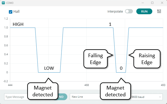
In the code above we only count when the sensor transitions from 0 (!val) to 1 (val !=old). In short, we detect the raising edge of the signal.
After the while loop, we calculate the time elapsed in seconds by subtracting the start time from the current time using micros() and dividing it by 1000000.0. From that we calculate the RPM (rotations per minute) by dividing the cnt by the elapsed time in seconds and multiplying it by 60 (a minute).
  float seconds = (micros() - start) / 1000000.0;
  float rpm = cnt / seconds * 60.0;
Finally, the code prints the calculated RPM value to the serial monitor using Serial.print() y Serial.println().
  Serial.print("rpm: ");
  Serial.println(rpm);
}
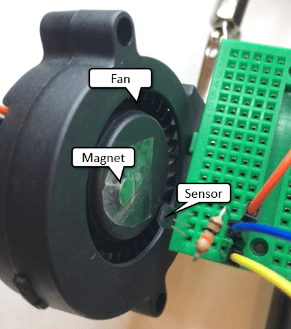
To try the code, attach a magnet in the right orientation to a rotating object let’s say a cooling fan. Then bring the sensor close enough and ensure that the magnet passes the sensor in each rotation. If you now run the code, you should be able to measure the RPM of the fan.
The code above should will work fine. But for faster rotating objects and more accurate measurements we can do even better by using interrupts. How that works, I’ll show you in the next section.
Example 3: A Faster Tachometer using Interrupts
The code example above uses a loop to poll the state of the Hall Effect sensor and if we detect a change in state from 0 to 1 we count this as one rotation. However, the speed of the Arduino is limited. If the object rotates faster then we can poll, we will miss changes in state and undercount.
Interrupts provide a solution for this problem. Instead of polling and looking for state changes we attach an interrupt to the sensor pin and whenever the state changes an ISR (interrupt service routine) is called. This will be a lot faster and the code is even simpler. Have a look:
const int hallPin = 2;
const int maxCnt = 100;

volatile int cnt = 0;

void count() {
  cnt++;
}

void setup() {
  Serial.begin(9600);
  pinMode(hallPin, INPUT);
  attachInterrupt(digitalPinToInterrupt(hallPin), count, FALLING);
}

void loop() {
  unsigned long start = micros();
  while (cnt < maxCnt) ;
  float seconds = (micros() - start) / 1000000.0;
  float rpm = cnt / seconds * 60.0;
  Serial.print("rpm: ");
  Serial.println(rpm);
  cnt = 0;
}
Let’s dive in and understand how this works in detail.
Constants and Variables
The code starts by defining the constants and variables.
const int hallPin = 2;
const int maxCnt = 100;

volatile int cnt = 0;
As before the hallPin constant specifies the pin to which the Hall Effect sensor is connected and the maxCnt constant sets the maximum count. The cnt variable is used to keep track of the number of rotations. Note that it is declared as “volatile“. That is necessary because we are going to use it inside of an interrupt service routine. More about this in the next section.
Count Function
El count() function is the interrupt service routine (ISR) that is called whenever the Hall Effect sensor detects a falling edge on the hallPin. ISRs should be as short as possible. In our case the function just increments the cnt variable by one, which is great for an ISR.
void count() {
  cnt++;
}
Setup Function
En el setup() function, we initialize the serial communication and set the hallPin as an input. Most importantly, we attach an interrupt to the hallPin that triggers the count() function on a falling edge.
Note that not all pins can be used for interrupts! It will depend on the microcontroller. In case of the Arduino Uno only pins 2 and 3 can be used for interrupts.
void setup() {
  Serial.begin(9600);
  pinMode(hallPin, INPUT);
  attachInterrupt(digitalPinToInterrupt(hallPin), count, FALLING);
}
Loop Function
En el loop() function we get the current time using the micros() function. Then, we enters a while loop that simply waits until the cnt variable reaches the maxCnt value. This ensures that we have counted enough rotations to calculate the speed accurately. Note that the counter is incremented outside the loop within the interrupt service routine count(). In short the Arduino is waiting in the while loop, while in parallel reacting to interrupts by calling the count() función.
If we have received enough counts the while loop exists. We then calculate the RPM (rotations per minute) as before and after resetting the cnt variable to zero, the main loop starts again.
void loop() {
  unsigned long start = micros();
  while (cnt < maxCnt) ;
  float seconds = (micros() - start) / 1000000.0;
  float rpm = cnt / seconds * 60.0;
  Serial.print("rpm: ");
  Serial.println(rpm);
  cnt = 0;
}
For more accurate but slower measurements of the rotational speed increase the value of the maxCnt constant. You will be averaging over more rotations, which will give you more stable readings but it will take longer. A lower maxCnt value, will give you faster RPM readings but they will fluctuate more.
That’s it! With this code, you can build a tachometer using an Arduino and a Hall Effect sensor to measure the speed of a rotating object.
Conclusión
In this tutorial, we have learned how to build a tachometer using a Hall Effect sensor and an Arduino. We started by understanding the basics of Hall Effect sensors and then introduced the A3144 Hall Effect sensor, which is commonly used in speed measurement applications.
Then we tested the A3144 sensor to ensure its functionality and proceeded to connect it to the Arduino. We explored three different examples to demonstrate the versatility of the sensor.
In example 1, we used the A3144 sensor as a magnetic switch, detecting the presence or absence of a magnetic field. This can be useful in various applications such as door/window sensors or proximity detection.
In example 2, we built a simple tachometer using the A3144 sensor. By attaching the sensor to a rotating object, we were able to measure its speed in revolutions per minute (RPM). This can be handy in applications like monitoring the speed of a motor or a fan.
In example 3, we improved upon the simple tachometer by utilizing interrupts. By configuring the Arduino to trigger an interrupt whenever the A3144 sensor detects a magnet, we achieved more accurate and reliable RPM measurements.
By following this tutorial, you should now have a good understanding of how to use the A3144 Hall Effect sensor with an Arduino to build a tachometer. If you have any questions or need further assistance, feel free to check out the frequently asked questions section.
Happy tinkering!
Frequently Asked Questions
Here are some commonly asked questions about building a tachometer using a Hall Effect sensor with an Arduino:
Q: What is a tachometer?
A: A tachometer is a device used to measure the speed of a rotating object. It provides information about the rotational speed in revolutions per minute (RPM).
Q: What is a Hall Effect sensor?
A: A Hall Effect sensor is a transducer that detects the presence of a magnetic field. It works on the principle of the Hall Effect, which states that when a conductor with current flowing through it is placed in a magnetic field, a voltage is generated perpendicular to both the current and the magnetic field.
Q: What are the advantages of Hall Effect sensors?
Hall effect sensors are generally immune to noise, light, or temperature. Since they have no mechanical parts they react fast and last pretty much forever. In addition, they are very small and therefore can fit in tight space.
Q: Why use a Hall Effect sensor for a tachometer?
A: Hall Effect sensors are commonly used in tachometers because they can accurately measure the speed of rotating objects without physical contact. This makes them ideal for applications where non-intrusive speed measurement is required.
Q: Why is the Hall Effect sensor not reacting?
A: Make sure that everything is correctly wired up. The A3144 is a unipolar Hall Effect Sensor and will react only to one pole of the magnet. Check that your magnet is strong enough.
Q: Can I use the A3144 to measure the strength of a magnetic field
The A3144 is a switching Hall Effect sensor and not suitable for that. You would need a linear Hall Effect sensor
Q: Can I use the A3144 with an ESP32
Not directly. The A3144 operates with 5V while the ESP operates with 3.3V. You would need a voltage level shifter.

I am Puneeth. I love tinkering with open-source projects, Arduino, ESP32, Pi and more. I have worked with many different Arduino boards and currently I am exploring, Arduino powered LoRa, Power line communication and IoT.
Michael Sailor
Wednesday 14th of February 2024
Hi, I have a sixslotted wheel that I am using in pace of the hall sensor. I am using an Arduino Nana ESP32 board and the reading I am getting are times the value that I read with my digital tach. What could be the problem?
Stefan Maetschke
Monday 19th of February 2024
Hi, without seeing the code and the hardware setup it is difficult to tell. You are mentioning a "six slotted wheel". Are you using six magnets and one Hall sensor? Or is your digital tachometer reading six times higher speed due to the six slotted wheel?
Art
Sunday 26th of November 2023
Thnks, code (for old arduino nano) needs pinMode(hallPin,INPUT); instead of pinMode(hallPin)
Stefan Maetschke
Monday 27th of November 2023
Indeed, Thanks! Code has been fixed.
Naveen
Thursday 26th of October 2023
Hi, I'm using the A3144 and am unable to produce the expected output. Would you be able to help me troubleshoot this? I tried using the exact same code that you did, still doesnt work.
Stefan Maetschke
Friday 27th of October 2023
Hi, what is the problem? Does the following code work for you? If not then there is a problem with the sensor or the wiring.
void setup() { Serial.begin(9600); pinMode(A0, INPUT); } void loop() { auto sensorValue = digitalRead(A0); Serial.print("Hall:"); Serial.println(sensorValue); delay(100); }