Have you ever wanted to build a project that utilizes a 4-digit or an 8-digit 7-segment display?
Driving a large number of 7-segment displays with an Arduino UNO can be challenging, as it requires many pins and complex software functions.
This is where the CD4511 7-segment driver IC comes in handy.
The CD4511 is a BCD-to-7-segment latch decoder driver integrated circuit, widely used in digital clocks, counters, and display systems.
CD4511 converts binary-coded decimal (BCD) data into a pattern of 7-segment displays.
Using the CD4511, you can connect your Arduino UNO to a larger number of 7-segment displays using fewer pins and software effort.
In this article, I will provide a connection diagram and code examples to help you use the CD4511 with your Arduino UNO.
Whether you’re just starting or an experienced maker, the CD4511 is a useful and powerful tool for your next 7-segment display project.
So grab your breadboard, and let’s dive in!
Components Needed To Build Arduino And CD4511 7-Segment Display Project
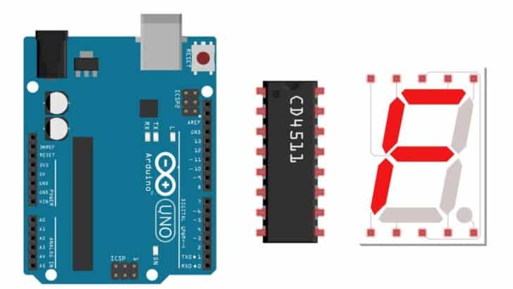
Componentes de hardware
- Arduino Uno Rev3 x 1
- CD4511 chip – BCD to 7-segment decoder x 1
- 7-segment display x 1 (optional)
- Alambre Dupont x 1 juego
- Cable USB Arduino (para alimentar Arduino y programar) x 1
- Arduino Power adapter x 1 (optional)
Software
Makerguides.com participa en el Programa de Asociados de Amazon Services LLC, un programa de publicidad de afiliados diseñado para proporcionar un medio para que los sitios ganen honorarios de publicidad mediante la publicidad y los enlaces a productos en Amazon.com.
Basics of The CD4511 BCD decoder
In this section, we will understand the basics of the CD4511 BCD decoder IC. It’s a low-cost BCD to the 7-segment decoder with many features and a super-easy display driver.
The CD4511 is a handy IC for driving 7-segment displays. It’s a CMOS device that’s designed to be low-power and noise-immune. This makes it ideal for a variety of applications.
The CD4511 takes binary-coded decimal (BCD) data and outputs the corresponding information to a 7-segment display.
The CD4511 has four BCD input and seven output bits for the 7-segment display.
The four BCD inputs are connected to the data inputs, while the seven outputs are connected to the segments of the 7-segment display.
The below image shows you the functional block diagram of the CD4511 IC.
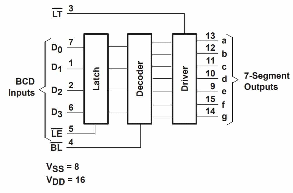
When you send a BCD number to the CD4511, decode it and light up the corresponding segments to display the number on the 7-segment display.
One of the great things about the CD4511 is its flexibility. It can be used with common-cathode and common-anode 7-segment displays, making it a popular choice for a wide range of projects.
It’s also easy to use – simply connect the inputs and outputs, and the CD4511 does the rest.
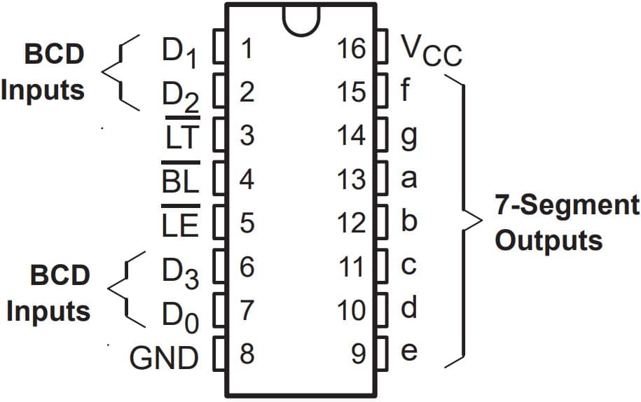
The below image shows the CD4511 pinout details.
Another benefit of the CD4511 is its low power consumption. This makes it ideal for battery-powered projects where power conservation is important.
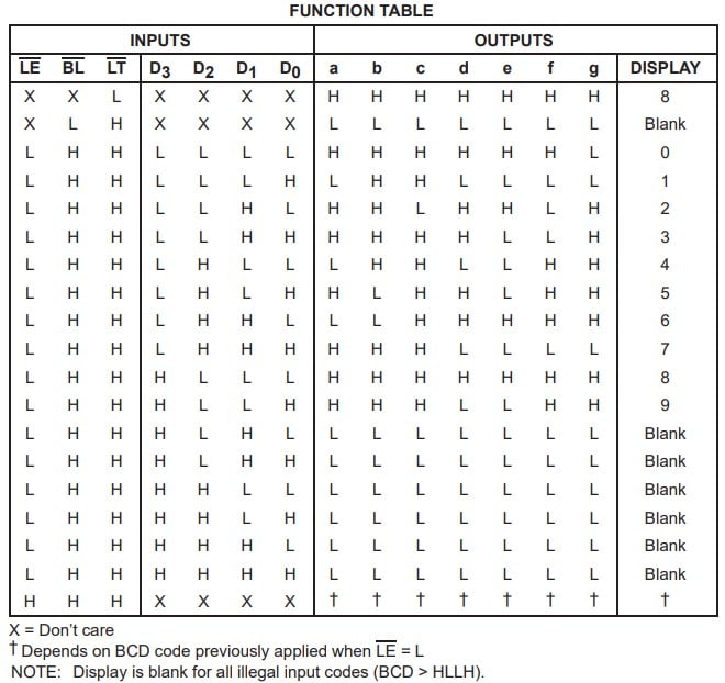
The CD4511 IC has a lamp test (LT) capability, which means all segments in the 7-segment display will light up.
If you want to turn off all the segments temporarily, the CD4511 also features an active-low blanking feature.
This feature allows you to create blinking effects, making your displays more dynamic and eye-catching. The below table summarizes the functions.
Whether you’re working on a simple project or a more complex one, the CD4511 is an excellent choice for driving 7-segment displays.
Features Of The CD4511
Here are the features of Arduino-compatible CD4511 IC:
- 4.5 V to 5.5 V operating voltage range
- High current sourcing capability (7.5 mA)
- High noise immunity
- Input latches for BCD code storage
- Balanced propagation delay and transition times
- 8 µA maximum current consumption at room temperature
- Segment blanking feature
- All lamp feature (to test and debug segments easily)
Pin Details Of The CD4511 IC
The BCD inputs are used to input binary-coded decimal data, which is decoded and then displayed on a 7-segment display.
The Lamp Test input is used to test all the segments in the 7-segment display. The Blanking input is used to turn off all the segments temporarily.
The seven-segment outputs drive the corresponding segments in the 7-segment display.
I have summarised the pin description of the CD4511 chip in the table below.
| Número de pin | Nombre de la clavija | Función de la clavija |
| 1 | D1 | BCD input data D1 |
| 2 | D2 | BCD input data D2 |
| 3 | #LT | Lamping test (Active Low) |
| 4 | #BL | Blanking capability (Active Low) |
| 5 | #LE | Latch enable (Active low input) |
| 6 | D3 | BCD input data D3 |
| 7 | D0 | BCD input data D0 |
| 8 | GND | Conexión a tierra |
| 9-15 | a-f | LCD segment drive pins |
| 16 | VCC | Power supply input pin. This pin should be decoupled using a 0.1 µF to 1.0 µF capacitor. |
Potential Applications Of The CD4511 IC
- Digital displays in clocks and calculators
- Control panels of a weather station to display temperature, pressure, etc.
- Numerical information displayed on weighing scales
- Measuring pieces of equipment, and
- Industrial process control systems. etc
Step-By-Step Instructions To Connect The CD4511 With Arduino UNO And 7-segment Display
In this section, we will build a project using Arduino UNO, 7-segment display, and the CD4511 module.
Las conexiones son fáciles de realizar y llevan mucho menos tiempo.
Empecemos con las conexiones de hardware.
How To Connect The 7 Segment Driver CD4511 to the Arduino UNO?
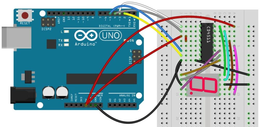
Below is the step-by-step connection guide to complete the Arduino and the CD4511 module.
Paso 1: Empezar con las conexiones GND
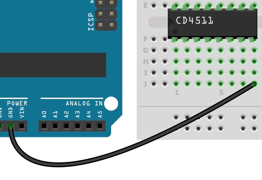
Connect the GND pin of the CD4511 module to the GND of the Arduino.
Elige cualquier pin GND disponible en el Arduino para la conexión.
Es una excelente práctica comenzar con las conexiones GND.
Step 2: Connect the BCD Lines to the module
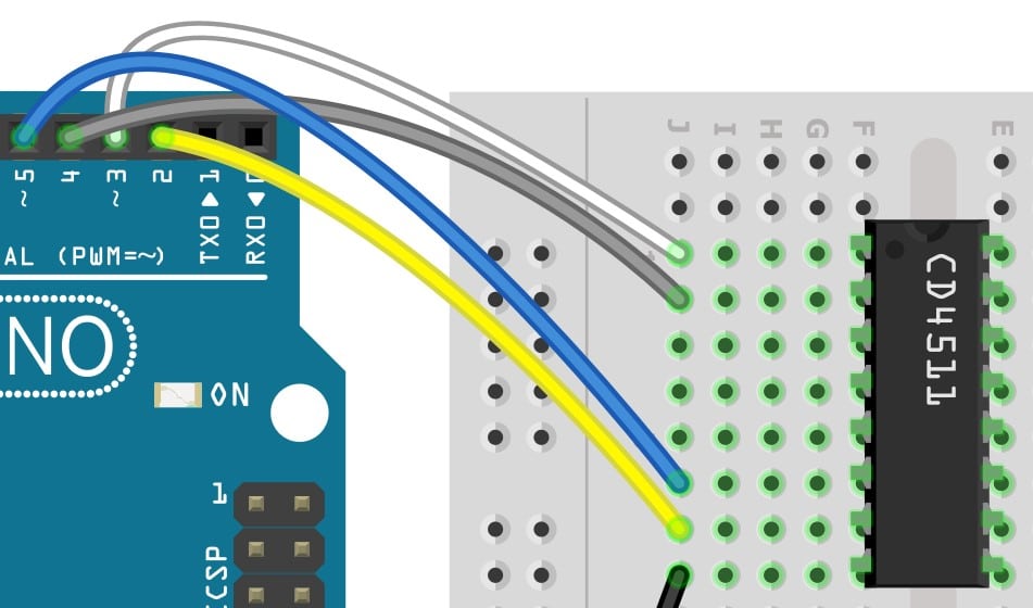
Connect the Arduino pins 2-5 to BCD data inputs pin on the CD4511.
Step 3: Terminate the Lamp test and Blank test inputs
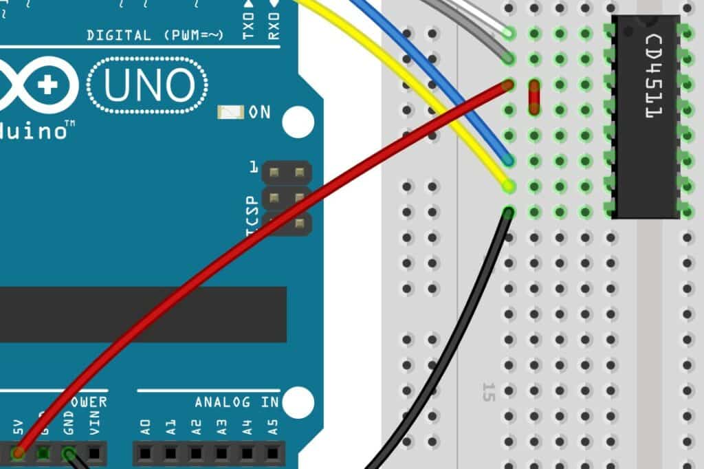
Connect pins 3 and 4 of the CD4511 IC to the Arduino 5V pin. The two pins are used to test the module. In this example, we will terminate them safely.
Step 4: Connect the Power line
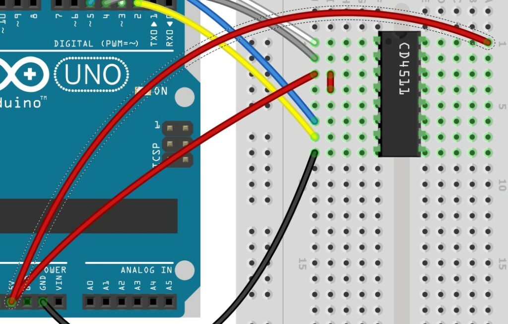
Connect the VCC pin on the CD4511 IC to 5 V pin on the Arduino UNO.
Step 5: Connect the 7-segment module
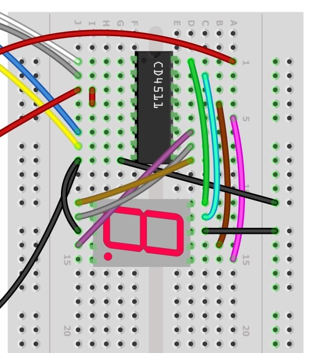
Connect the 7-segment module to the CD4511 IC.
Step 6: Complete connection
Congratulations! This completes all the required connections.
Arduino Code Example For The CD4511 Arduino Module Project
En esta sección, puedes encontrar el sketch completo de Arduino y la información sobre la instalación de las librerías necesarias.
The complete Arduino Code For The CD4511 Arduino Project Example
 /*
Example of how to drive a seven-segment display using HCF4511   or similar

This sketch drives the display in order to show a number from   0 to 9 every time a button connected to A0 is pressed.
Source: https://projecthub.arduino.cc/Arduino_Scuola/36b84c1e-70fc-4f09-87a3-62fb39dc21cb
*/

//Declaration   of Arduino pins used as HCF4511 inputs
const int A = 2;
const int B = 3;
const int C = 4;
const int D = 5;

void setup() {
  pinMode(A0, INPUT);
  pinMode(A, OUTPUT); //LSB
  pinMode(B, OUTPUT);
  pinMode(C, OUTPUT);
  pinMode(D, OUTPUT); //MSB
}

int count = 0; //the variable used to show the number

void   loop() {
  if (digitalRead(A0) == LOW) //if button is pressed
  {
    count++;
    delay(200); //the delay prevent from button bouncing
    if (count ==   10) //we want to count from 0 to 9!
      count = 0;
    to_BCD(); //convert   to binary
  }

  if (count == 10)
    count = 0;
}

void to_BCD()
{
  if (count == 0) //write 0000
  {
    digitalWrite(A, LOW);
    digitalWrite(B, LOW);
    digitalWrite(C, LOW);
    digitalWrite(D, LOW);
  }

  if (count == 1) //write 0001
  {
    digitalWrite(A, HIGH);
    digitalWrite(B, LOW);
    digitalWrite(C, LOW);
    digitalWrite(D, LOW);
  }

  if (count == 2) //write 0010
  {
    digitalWrite(A, LOW);
    digitalWrite(B, HIGH);
    digitalWrite(C, LOW);
    digitalWrite(D, LOW);
  }

  if (count == 3) //write 0011
  {
    digitalWrite(A, HIGH);
    digitalWrite(B, HIGH);
    digitalWrite(C, LOW);
    digitalWrite(D, LOW);
  }

  if (count == 4) //write 0100
  {
    digitalWrite(A, LOW);
    digitalWrite(B, LOW);
    digitalWrite(C, HIGH);
    digitalWrite(D, LOW);
  }

  if (count == 5) //write 0101
  {
    digitalWrite(A, HIGH);
    digitalWrite(B, LOW);
    digitalWrite(C, HIGH);
    digitalWrite(D, LOW);
  }

  if (count == 6) //write 0110
  {
    digitalWrite(A, LOW);
    digitalWrite(B, HIGH);
    digitalWrite(C, HIGH);
    digitalWrite(D, LOW);
  }

  if (count == 7) //write 0111
  {
    digitalWrite(A, HIGH);
    digitalWrite(B, HIGH);
    digitalWrite(C, HIGH);
    digitalWrite(D, LOW);
  }

  if (count == 8) //write 1000
  {
    digitalWrite(A, LOW);
    digitalWrite(B, LOW);
    digitalWrite(C, LOW);
    digitalWrite(D, HIGH);
  }

  if (count == 9) //write 1001
  {
    digitalWrite(A, HIGH);
    digitalWrite(B, LOW);
    digitalWrite(C, LOW);
    digitalWrite(D, HIGH);
  }
}
The code is written in a straightforward way. If you have to display 1 on the 7-segment display, you have to send 0001 to the BCD input pins of the CD4511 decoder.
  if (count == 1) //write 0001
  {
    digitalWrite(A, HIGH);
    digitalWrite(B, LOW);
    digitalWrite(C, LOW);
    digitalWrite(D, LOW);
  }
Another way to decrease the code length is by defining a function that takes the count value as input and maps it onto the BCD inputs.
FAQs About The CD4511 And Arduino Projects
I have included a list of the most frequently asked questions about projects built using Arduino and the BCD to the 7-segment module – CD4511.
If you have more questions, please post them in the comments section. I will be happy to answer them.
1. What is the CD4511 IC?
The CD4511 is an IC commonly used to control 7-segment displays in various applications, such as digital clocks, calculators, and other display-based projects.
It acts as a decoder and driver, converting binary-coded decimal (BCD) inputs into outputs. The binary outputs can control the segments of the 7-segment display.
It is found in many hobby projects and commercial applications where the 7-segment displays are used.
2. How does the CD4511 work with an Arduino board?
The CD4511 works in conjunction with an Arduino board by receiving binary inputs from the board, decoding them, and then driving the corresponding segments of the 7-segment display.
The CD4511 requires a connection to the power supply (5 V), ground, and data inputs from the Arduino board to function properly (BCD inputs).
3. What are the advantages of using the CD4511 with an Arduino board?
The CD4511 offers several advantages when used with an Arduino board.
- It is a compact and cost-effective solution for controlling 7-segment displays, combining the functions of a decoder and driver into a single IC.
- It also reduces the amount of wiring and the number of components required, making the overall project simpler and easier to construct.
- It simplifies the software and saves time and software complexity.
4. How many inputs does the CD4511 have?
The CD4511 has four input pins. You can use the pins to receive binary-coded decimal (BCD) data from the Arduino UNO board.
The CD4511 IC decodes the data and controls the segments of the 7-segment display.
There are test inputs as well to perform a basic quick test. Please refer to the basics of the CD4511 section above for more details.
5. What is the maximum current that the CD4511 can drive?
The CD4511 is capable of driving a maximum current of 15 mA per segment.
This allows it to power the most common 7-segment displays, including those used in digital clocks, calculators, and other display-based projects.
6. Can the CD4511 be used with other microcontrollers besides the Arduino board?
Yes, the CD4511 can be used with other types of microcontrollers besides the Arduino board.
However, the specific wiring and code required will depend on the microcontroller being used, as well as the type of 7-segment display being used.
It is important to consult the datasheet for both the CD4511 and the microcontroller to ensure compatibility and proper use.
Conclusión
In this article, we have explored all the key features and capabilities of the CD4511.
I have provided a comprehensive guide on how to use it with an Arduino UNO.
With the step-by-step connection guide and working code examples, you have all the information you need to start your CD4511 and Arduino project.
I hope that this article has been of great help to you in learning about the CD4511 and how to use it with Arduino.
If you have any questions, comments, or suggestions, please do not hesitate to reach out.
My goal is to ensure that you have all the information and support you need to be successful in your projects in one place.
If you have found any info missing or an improvement, please let me know.
Keep tinkering. Keep learning!
Benne is professional Systems Engineer with a deep expertise in Arduino and a passion for DIY projects.