The MQ-7 Gas Sensor is a popular sensor used to detect the presence of carbon monoxide (CO) gas in the air. In this article, we will explore how to use this sensor with an Arduino to display the gas level on an LCD display.
Carbon monoxide is a colorless and odorless gas that can be harmful or even fatal if inhaled in high concentrations. It is produced by the incomplete combustion of fossil fuels, such as gas, oil, and coal.
In this tutorial, we will guide you through the process of connecting the MQ-7 Gas Sensor to an Arduino and displaying the gas level on an LCD display. We will also provide you with the necessary code to get started.
By the end of this tutorial, you will have a working system that can detect gas levels and display them on an LCD display. This project can be particularly useful in environments where carbon monoxide is a potential risk, such as homes with gas appliances or workshops with gas-powered tools.
Before we begin, let’s take a look at the parts you will need for this project.
Required Parts
Below you will find the parts required for this project. Instead of the larger 20×4 LCD display you could also use a smaller 16×2 LCD display. Just make sure it has an I2C interface and not the also common SPI interface.

Arduino Uno

Dupont Wire Set

Tablero de pruebas

USB Cable for Arduino UNO
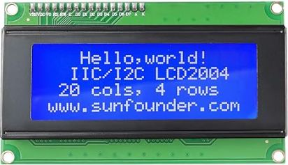
LCD Display
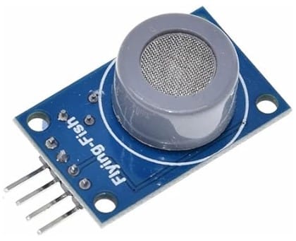
MQ-7 Gas Sensor
Makerguides.com is a participant in the Amazon Services LLC Associates Program, an affiliate advertising program designed to provide a means for sites to earn advertising fees by advertising and linking to products on Amazon.com. As an Amazon Associate we earn from qualifying purchases.
Introducing the MQ-7
The MQ-7 Gas Sensor is a small module that can detect carbon monoxide gas in the air. It operates on the principle of chemoresistance, where the electrical resistance of the sensor changes when it comes into contact with CO gas.
The MQ-7 is specifically aimed at the detection of carbon monoxide (CO), while the other sensors in the MQ series are optimized for other gases. For instance:
- MQ-2: Fairly universal in the detection of gases.
- MQ-3: Designed primarily for detecting alcohol.
- MQ-4: Designed primarily for detecting methane and natural gas.
- MQ-5: Designed for LPG and natural gas.
- MQ-6: Designed specifically for LPG detection.
- MQ-7: Focused on carbon monoxide (CO) detection.
- MQ-8: Primarily for hydrogen gas detection.
- MQ-9: Detects carbon monoxide (CO) and flammable gases.
The MQ-2 is a bit of an exception in the sense that it very generic and not optimized for a specific gas. Note that we have in-depth tutorials for some of these sensors:
- How to use the MQ-2 Gas Sensor with Arduino and an OLED
- Air Pollution Monitoring and Alert System Using Arduino and mq135
- MQ3 Sensor & Arduino: Building An Alcohol Detector
- Using the MQ4 Methane Gas Sensor With Arduino Made Easy
Internals of the MQ-7 Gas Sensor
In this section we look at the internal workings of the MQ-7 sensor. The sensor uses a layer of a metal oxide (SnO2). When carbon monoxide comes into contact with this layer, it reacts with the SnO2. This results in a change in the material’s resistance.
The picture below is taken from the datasheet of the MQ-7 sensor and show its components and internal circuitry.
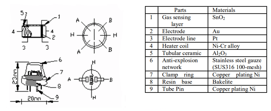
If you look closely you can see that the sensing layer (1) is wrapped in a heater coil (4). It provides the heat needed for the chemical reaction of the gas with the SnO2 layer to occur. The heating element is the reason, why the sensor gets warm in operation.
Around the sensing layer and the heater coil is a tubular ceramic (5) for physical protection and thermal insulation. The mesh on top (6) ensures that the gas doesn’t explode.
Finally, we have the electrodes (2, 3), made of gold (Au) and platinum (Pt). They are attached to the sensing layer. These electrodes measure the changes in the resistance of the sensing layer.
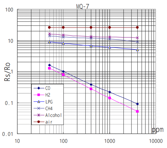
Sensitivity Characteristics of the MQ-7 Gas Sensor
The MQ-7 gas sensor is designed to specifically detect carbon monoxide (CO). As you can see in the diagram below, it reacts much more strongly to CO and H2 (slope of the line), compared to other gases such as LPG (liquefied petroleum gas), methane (CH4) and alcohol.
Humidity and Temperature Dependency of the MQ-7 Gas Sensor
Note, however, that the MQ-7 is influenced by humidity and temperature. The following graph shows the change in resistance depending on ambient temperature and relative humidity.
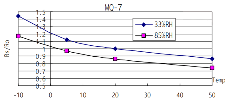
You can see that the curve flattens for higher temperature and shifts for down when humidity increases. If you need accurate and stable readings, you may need additional temperature and a humidity sensors to compensate for those dependencies. Also note, that the MQ-7 has a pre-heat time of at least 48 hours.
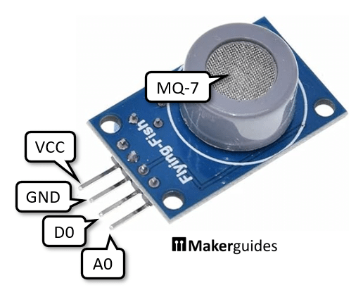
MQ-7 Sensor Pinout
Instead of using the raw MQ-7 sensor described above, it is easier to use a MQ-7 module that can be directly connected to an Arduino. These module typically have four pins. The VCC pin is for the 5V power supply and the GND pin needs to be connected to ground. The A0 pin provides the analog output voltage proportional to the gas concentration. And the D0 pin outputs a digital signal (HIGH or LOW).
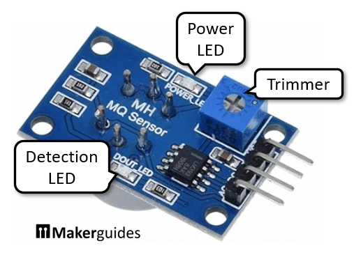
On the backside of the module you will find a trimmer to adjust the switching threshold for D0. There you also see a power LED (red) that is lit when the module has power. In addition there is a detection LED (green) that comes on when gas is detected (D0=HIGH) above the threshold set by the trimmer.
Testing the MQ-7 Gas Sensor
You can easily test the function of the module even without an Arduino. Connect VCC and GND to a 5V power supply and the red power LED at the back of the module should come on. Now wait a few seconds until the sensor has warmed up. You should feel that it gets warm. If not check your power supply connection to the sensor.
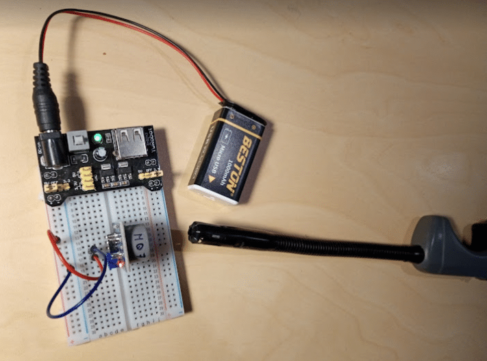
If you now let the gas of a lighter stream out (don’t ignite it) or spray perfume/alcohol close to the sensor, you should see the green LED on the back come on for a short time. While the sensor is optimized for carbon monoxide (CO), it still reacts to these other gases. If not, try to adjust the trimmer to change the detection threshold.
In the next section, I will show you how to connect the MQ-7 to the Arduino and write the necessary code to display gas levels.
Connecting the Parts
In this section we will connect the MQ-7 sensor and the LCD display to the Arduino. First, let’s connect power from the Arduino to the power rails of the breadboard (red and blue wire from 5V and GND pin). Then connect power from the power rails to MQ-7 sensor and the LCD display (red and blue wires).
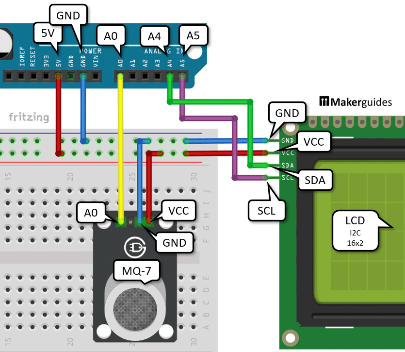
After that connect the analog output A0 of the MQ-7 sensor to the analog input A0 of the Arduino (yellow wire).
Finally we need to connect the I2C pins SCL and SDA of the display to the A4 and A5 inputs of the Arduino (purple and green wires, SCL->A5, SDA->A4).
That completes the connection of the parts. If you need more details regarding the wiring of the components have a look at the table below and at our tutorial Character I2C LCD with Arduino Tutorial (8 Examples).
| From | Pin | Wire color | To | Pin |
| Arduino | 5V | Rojo | Tablero de pruebas | Positive rail |
| Arduino | GND | Blue | Tablero de pruebas | Negative rail |
| MQ-7 | GND | Blue | Tablero de pruebas | Negative rail |
| MQ-7 | VCC | Rojo | Tablero de pruebas | Positive rail |
| MQ-7 | Out/Signal/A0 | Amarillo | Arduino | A0 |
| LCD | VCC | Rojo | Tablero de pruebas | Positive rail |
| LCD | GND | Blue | Tablero de pruebas | Negative rail |
| LCD | SCL | Purple | Arduino | A5 |
| LCD | SDA | Green | Arduino | A4 |
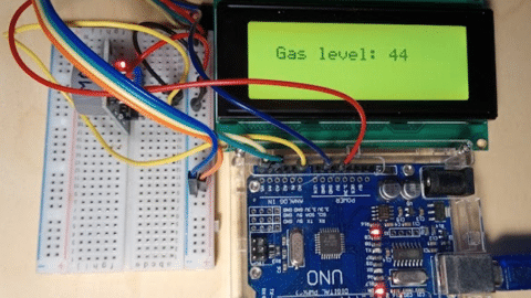
In the following picture you can see how the complete wiring looks like in reality. I know it is a bit messy but works ; )
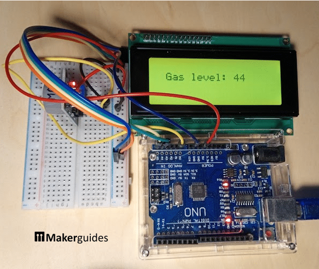
In the next section we are going to write the code to display the measured gas levels on the LCD display.
Writing the Arduino Code – 1. Example
We start with a base implementation that we will later expand a bit. The following code reads the value from the MQ-7 every second, prints it to the Serial Monitor and additionally displays it on the LCD.
#include "LiquidCrystal_I2C.h"

LiquidCrystal_I2C lcd = LiquidCrystal_I2C(0x27, 20, 4);

void setup() {
  Serial.begin(9600);
  lcd.init();
  lcd.backlight();
}

void loop() {
  int sensorValue = analogRead(A0);
  Serial.print("Gas:");
  Serial.println(sensorValue);

  lcd.clear();
  lcd.setCursor(2, 1);
  lcd.print(sensorValue);

  delay(1000);
}
Let’s take a closer look at the code and understand how it works.
Library and Object Initialization
To begin with, we include the LiquidCrystal_I2C library, which provides functions to control the LCD display.
#include "LiquidCrystal_I2C.h"

LiquidCrystal_I2C lcd = LiquidCrystal_I2C(0x27, 20, 4);
If you don’t have this library already installed, you will need to install it. Just go to Tools -> Manage Libraries ... and install LiquidCrystal I2C by Frank de Brabander:
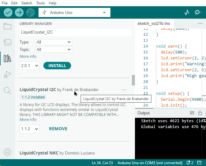
LiquidCrystal I2C library We then create an instance of the LiquidCrystal_I2C class called lcd. The parameters passed to the constructor are the I2C address of the LCD (0x27) and the dimensions of the display (20 columns and 4 rows). If you use the smaller 16×2 LCD display, you have to change these dimensions to (16, 2).
Also, if you run the code and cannot connect to the display, check that your display has the I2C address 0x27. Sometimes it is printed on the backside of the display module. If not, then you can run an I2C scan to detect it. Install the I2CScanner library and run the following code.
#include "I2CScanner.h"

I2CScanner scanner;

void setup() {
  Serial.begin(9600);
  while (!Serial) {};
  scanner.Init();
}

void loop() {
  scanner.Scan();
  delay(5000);
}
Setup Function
En el setup() function, we initialize the serial communication with a baud rate of 9600 using Serial.begin(9600). This allows us to view the gas sensor readings on the serial monitor for debugging purposes. We then initialize the LCD display using lcd.init() and turn on the backlight using lcd.backlight().
void setup() {
  Serial.begin(9600);
  lcd.init();
  lcd.backlight();
}
Loop Function
El loop() function is where the main functionality of the code resides. It runs repeatedly in an infinite loop.
First, we read the analog value from the gas sensor connected to pin A0 using analogRead(A0). The sensor value is stored in the variable sensorValue.
void loop() {
  int sensorValue = analogRead(A0);
Next, we print the gas sensor value to the serial monitor for debugging purposes using Serial.print() y Serial.println(). This allows us to monitor the gas level in real-time.
  Serial.print("Gas:");
  Serial.println(sensorValue);
We then clear the LCD display using lcd.clear() to remove any previous content. After that, we set the cursor position to column 2 and row 1 using lcd.setCursor(2, 1). This is where we will display the gas sensor value on the LCD.
  lcd.clear();
  lcd.setCursor(2, 1);
Using lcd.print(), we print the sensorValue on the LCD display.
lcd.print(sensorValue);
Finally, we introduce a delay of 1000 milliseconds (1 second) using delay(1000) before the loop repeats.
delay(1000);
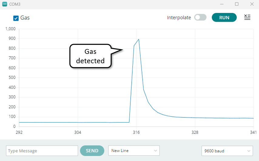
Running the Code
Now let’s test the code. If you open the Serial Plotter and expose the MQ-7 to a bit of the gas from a lighter you should see a peak like the one I detected.
In the next section we extend our code a bit with a blinking warning text, if the gas levels exceed a certain threshold.
Writing the Arduino Code – 2. Example
In this second example, we factor out some code in two functions display() y warning(). This will allow us to simplify the main loop and add a blinking effect if the gas levels are getting to high. Below you will find the complete code and it’s explantion.
#include "LiquidCrystal_I2C.h"

LiquidCrystal_I2C lcd = LiquidCrystal_I2C(0x27, 20, 4);

void display(int sensorValue) {
  lcd.setCursor(2, 1);
  lcd.print("Gas level:");
  lcd.setCursor(13, 1);
  lcd.print(sensorValue);
  delay(1000);
}

void warn() {
  delay(500);
  lcd.setCursor(2, 2);
  lcd.print("Warning!");
  lcd.setCursor(2, 3);
  lcd.print("High gas level!");
}

void setup() {
  Serial.begin(9600);
  lcd.init();
  lcd.backlight();
}

void loop() {
  int sensorValue = analogRead(A0);
  Serial.print("Gas:");
  Serial.println(sensorValue);

  lcd.clear();
  if (sensorValue > 100) {
    warn();
  }
  display(sensorValue);
}
We start by including the LiquidCrystal_I2C library and creating the lcd object as before. Next we define the display() función.
Display function
El display() function is responsible for displaying the gas level on the LCD display. It takes the sensor value as a parameter and prints the gas level on the second row of the display. The function also includes a delay of 1 second to allow time for the reading to be displayed.
void display(int sensorValue) {
  lcd.setCursor(2, 1);
  lcd.print("Gas level:");
  lcd.setCursor(13, 1);
  lcd.print(sensorValue);
  delay(1000);
}
Warning function
El warn() function is called when the gas level exceeds a certain threshold (in this case, 100). It displays a warning message on the LCD display, indicating a high gas level. The function includes a delay of 500ms to allow time for the warning message to be displayed.
void warn() {
  delay(500);
  lcd.setCursor(2, 2);
  lcd.print("Warning!");
  lcd.setCursor(2, 3);
  lcd.print("High gas level!");
}
Setup function
El setup() function remains unchanged. We initialize the serial communication and the LCD display and turn the backlight on.
void setup() {
  Serial.begin(9600);
  lcd.init();
  lcd.backlight();
}
Loop function
El loop() function is where the main logic of the program resides. It starts by reading the sensor value from analog pin A0 and printing it to the serial monitor. The LCD display is then cleared.
If the sensor value is greater than 100, indicating a high gas level, the warn() function is called to display a warning message on the LCD display. After that the display() function is called to display the gas level .
void loop() {
  int sensorValue = analogRead(A0);
  Serial.print("Gas:");
  Serial.println(sensorValue);

  lcd.clear();
  if (sensorValue > 40) {
    warn();
  }
  display(sensorValue);
}
Since we clear the display in between and wait for 500ms in the warn() function, this will result in a blinking display if the gas level exceeds 100.
And that’s it. We now have a system that measures carbon monoxide (CO) levels and shows them on an LCD display.
Conclusión
In this tutorial, we have learned how to use the MQ-7 Gas Sensor with an Arduino to display the gas level on an LCD display. We have covered the necessary parts, the connection process, and provided you with an example Arduino code.
Remember, carbon monoxide gas can be dangerous, so it’s important to have a reliable gas sensor like the MQ-7 to ensure the safety of your environment. With the knowledge gained from this tutorial, you can now build your own gas monitoring system.
If you have any further questions or need additional assistance, please refer to the Frequently Asked Questions section or check out the provided links for more resources.
Frequently Asked Questions
In this section, we will address some common questions that may arise when working with the MQ-7 Gas Sensor and an Arduino to display gas levels on an LCD display.
How accurate is the MQ-7 Gas Sensor?
The accuracy of the MQ-7 Gas Sensor depends on various factors such as temperature, humidity, and the presence of other gases. It is important to calibrate the sensor properly.
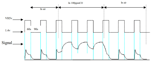
However, even then it may be difficult to get accurate measurement. The datasheet states that the sensor has to perform high- and low-heating cycles but the simple MQ-7 sensor module does not support this. We would need to modify hardware (and the software). For instruction on the modification have a look at this tutorial: Arduino CO Monitor Using MQ-7 Sensor.
In short, our project can provide a good indication of gas levels and is sufficient for a warning system, but will not show precise CO measurements in PPM unit.
Can I use a different gas sensor with this setup?
Yes, you can use a different gas sensor with this setup. However, you may need to make some modifications to the code and connections depending on the specifications of the sensor. It is important to ensure compatibility and adjust the code accordingly.
How can I calibrate the MQ-7 Gas Sensor?
Calibrating the MQ-7 Gas Sensor involves exposing it to a known concentration of the target gas and adjusting the sensitivity of the sensor accordingly. The datasheet says for calibration to expose the detector to 200ppm CO in air and use a Load resistance (RL) of about 10 KΩ.
Can I display gas levels in other units?
Yes, you can display gas levels in other units. Currently we simply show the value from the analog input which is in the range [0..1023]. Typically, you would want to measure in parts per million (ppm) but that would require a calibration of the sensor. Displaying the gas levels in PPM would then achieved by a simple scaling of the analog input reading.
How can I improve the sensitivity and accuracy of the MQ-7 Gas Sensor?
To improve the sensitivity and accuracy of the MQ-7 Gas Sensor, you can consider implementing temperature and humidity compensation techniques. Additionally it is important to minimize the influence of other gases that may interfere with the sensor’s measurements.
Can I use multiple MQ-7 Gas Sensors simultaneously?
Yes, you can use multiple MQ-7 Gas Sensors simultaneously with an Arduino. Each sensor will require its own set of connections and a different I2C address. However, keep in mind that using multiple sensors may require additional power and may impact the overall performance of your project.
How can I protect the MQ-7 Gas Sensor from external factors?
To protect the MQ-7 Gas Sensor from external factors, you can consider using a protective enclosure or housing. This can help shield the sensor from dust, moisture, and other contaminants that may affect its performance. Additionally, proper ventilation and avoiding exposure to extreme temperatures can also contribute to the longevity of the sensor.
Can I use the MQ-7 Gas Sensor for detecting other gases?
The MQ-7 Gas Sensor is primarily designed for detecting carbon monoxide (CO) gas. While it may respond to other gases to some extent, its sensitivity and accuracy may not be optimized for them. If you need to detect other gases, it is recommended to use sensors specifically designed for those gases to ensure reliable and accurate measurements.
Remember, if you have any specific questions or concerns regarding the MQ-7 Gas Sensor or its implementation with an Arduino and LCD display, it is always best to refer to the sensor’s datasheet or consult the manufacturer for detailed information and support.
Links
- MQ-7 Gas Sensor Datasheet
- Arduino Official Website
- LiquidCrystal_I2C Library
- Arduino CO Monitor Using MQ-7 Sensor

I am Puneeth. I love tinkering with open-source projects, Arduino, ESP32, Pi and more. I have worked with many different Arduino boards and currently I am exploring, Arduino powered LoRa, Power line communication and IoT.