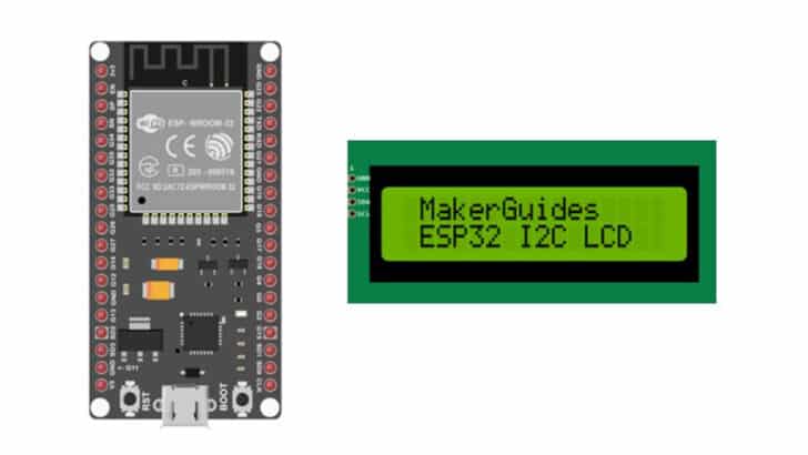
Adding a simple display to your ESP32 board can take your project and HMI feature to the next level.
A simple display such as an I2C based 16×2 display will help you to bring many possibilities to build projects faster and more efficiently.
You don’t have to reach for a laptop or mobile every time to learn about the status of the system and ESP32.
You can view data directly on a small screen as part of your project. Imagine atmospheric climate data or remote station monitoring.
A simple status update of the sensor data on the display before you send it to the cloud can be helpful for a quick visual assessment.
In this article, I have provided a step-by-step guide to connecting an I2C LCD with an ESP32.
I have also shared a working code example for ESP32, which you can easily use to test your connections, and discussed how to create and use symbols on the display.
By the end of this article, you will find a few frequently asked questions about the ESP32 and the character LCD interface.
So, grab your breadboard, and let’s get started.
(I also have an article on How To Control A Character I2C LCD with Arduino if you want to work with an Arduino microcontroller instead.
Components Needed To Build ESP32 And I2C LCD Module
Componentes de hardware
- Alambre Dupont x 1 juego
- Micro USB Cable for ESP32 (for powering Arduino and programming) x 1
Software
Guide
Makerguides.com participa en el Programa de Asociados de Amazon Services LLC, un programa de publicidad de afiliados diseñado para proporcionar un medio para que los sitios ganen honorarios de publicidad mediante la publicidad y los enlaces a productos en Amazon.com.
Basics of The ESP32 And I2C LCD Module
In this section, we will understand the basics of the ESP32 that are useful to complete the I2C LCD project.
So, What makes ESP32 so helpful and widely used?
ESP32 is a powerful microcontroller. I have listed the key features of ESP32 and the applications that make ESP32 a first choice in your next wireless project:
- Internet Of Things (IoT) – ESP32 is my first choice for IoT projects. ESP32 consumes low power, and it is affordable. It has built-in Wi-Fi and Bluetooth and comes with various supported protocols such as MQTT, HTTP, and more.
- Home Automation is a possibility with ESP32. You can control lights, heating, door locks, and more.
- ESP32 is considerably powerful when compared with Arduino. You can use it in robotics, image sensing, colour processing, and more.
- ESP32 has built-in hardware support for processing audio and video. Your following speech processing project can explore ESP32 capabilities!
- ESP32 modules also come with built-in sensors making environment sensing projects’ build time shorter.
- There is a vast community working with ESP32, which means you get many examples, support, and access to easy learning projects like this one.
You will see a pinout of an ESP32 module in the below image:
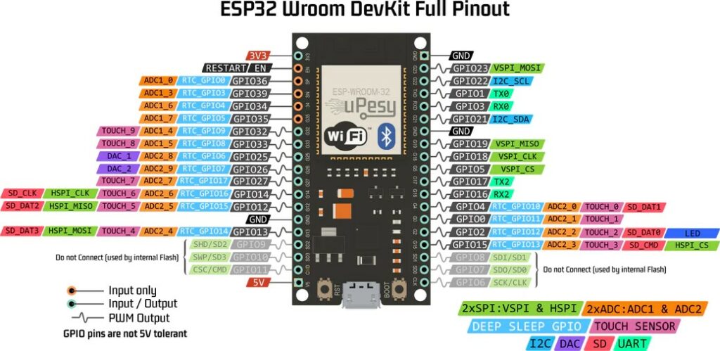
I only need I2C lines to connect to the LCD module for our project. I2C protocol uses two lines SDA and SCL. The SCL is a serial clock line, and SDA is a Serial Data line.
Since the I2C LCD consumes only two pins of the ESP32, keeping the wiring to a minimum is a better choice, and most of the ESP32 pins are available for other connections when necessary.
Various sources can power the ESP32. You can power it from USB, an external power supply, or batteries. To enable long-term functionality, you should employ deep sleep modes. Sleep modes allow you to conserve power ad extend battery life.
My personal preference is to use USB power always during development.
The below table summarizes the connections needed to I2C LCD (in general, any I2C device) and ESP32.
| I2C LCD | ESP32 | Observaciones |
| I2C Clock pin | SCL (GPIO 22, default) | You can change the pins to which the SCL function is mapped in ESP32. |
| I2C Data pin | SDA (GPIO 21, default) | You can change the pins to which the SDA function is mapped in ESP32. |
| Fuente de alimentación | 3.3 V or 5 V | Usually, 3.3 V or 5 V is sufficient |
| Tierra | GND | Conexiones a tierra |
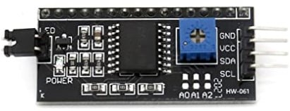
What if you don’t have an I2C LCD but a parallel data LCD?
No worries. Here is a picture of an I2C module that can act like a bridge between 8 bit LCD and your ESP32 I2C lines.
You can find I2C LCDs used in many places. I2C LCD is a very commonly used display.
Here are a few examples of cases where you can find applications for the I2C LCD
- Embedded Systems: I2C LCDs are widely used in embedded systems as they demand significantly less memory and can be used to display sensor readings, status messages, etc.
- Smart Home Devices: I2C LCDs can also be used in smart home devices like thermostats and home automation systems. Use cases: display temperature readings, device status, error condition, etc.
- Automotive Applications: I2C LCDs are used in automotive applications.Example: dashboard displays
- Medical Devices: I2C LCDs are used in medical devices to display patient data, medicine info, and much more
Because the LCDs cost less and are easy to work with, they find a lot of applications.
In the next section, I’ll show you how to connect the I2C LCD to the ESP32.
Step-By-Step Instructions To Connect The LCD Module with ESP32
In this section, we will build a project using ESP32 and I2C LCD. Since we use the I2C protocol, you can complete the connections with fewer wires.
Empecemos con las conexiones de hardware.
How To Connect The I2C LCD module with ESP32?
Below is the step-by-step connection guide to complete the ESP32 and I2C LCD modules.
Paso 1: Empezar con las conexiones GND
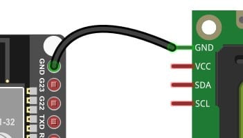
Connect the GND pin of the ESP32 module to the GND of the Arduino. Choose any GND pins available on the ESP32 for the connection. It is an excellent practice to start with the GND connections.
Paso 2: Conectar la línea I2C SCL
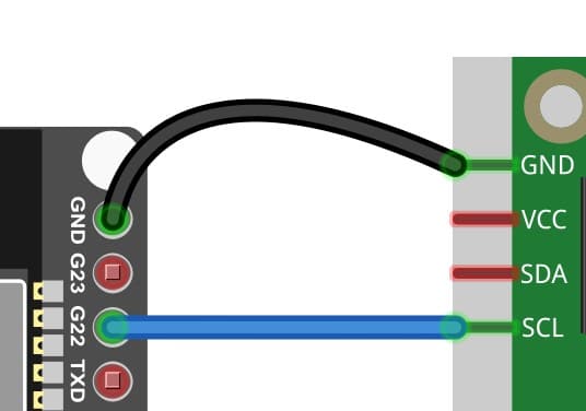
Connect the SCL pin on the I2C LCD module to GPIO22 on the ESP32.
Paso 3: Conectar la línea I2C SDA
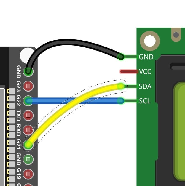
Connect the SDA pin on the I2C LCD to ESP32’s GPIO 21.
Paso 4: Conectar la línea de alimentación (cable rojo)
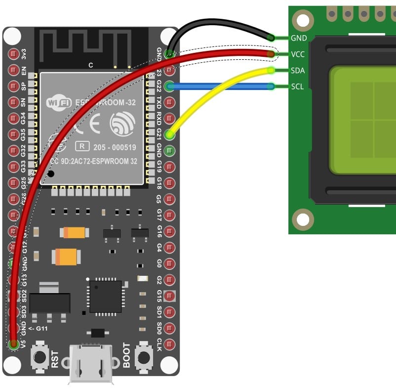
Connect the VCC pin on the ESP32 to the supply pin of the I2C LCD module.
Paso 5: La conexión completa
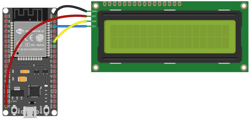
Congratulations. In the coming section, we will go through the code you can program to verify the connections.
ESP32 Code Example For The I2C LCD Project
In this section, you can find the complete ESP32 code to test the I2C LCD connections. Please follow the instructions in the guide to install the ESP32 core on Arduino UNO.
 #include "LiquidCrystal_I2C.h"

LiquidCrystal_I2C lcd(0x3F, 16, 2); // set the LCD address to 0x3F for a 16 chars and 2 line display

void setup() {
  lcd.init();
  lcd.clear();
  lcd.backlight();      // Make sure backlight is on

  // Print a message on both lines of the LCD.
  lcd.setCursor(2, 0);  //Set cursor to character 2 on line 0
  lcd.print("Hello world!");

  lcd.setCursor(2, 1);  //Move cursor to character 2 on line 1
  lcd.print("LCD Tutorial");
}

void loop() {
}
Let’s walk through the code.
#include "LiquidCrystal_I2C.h"
This line includes the header file for the LiquidCrystal_I2C library. This library interfaces with LCDs that use the I2C protocol.
LiquidCrystal_I2C lcd(0x3F, 16, 2);
This line initializes a LiquidCrystal_I2C object called “lcd”. The object is created with three parameters: the I2C address of the LCD (in this case 0x3F), the number of columns (16), and the number of rows (2) of the LCD.
void setup() {
  lcd.init();
  lcd.clear();
  lcd.backlight();      // Make sure backlight is on

  // Print a message on both lines of the LCD.
  lcd.setCursor(2, 0);  //Set cursor to character 2 on line 0
  lcd.print("Hello world!");

  lcd.setCursor(2, 1);  //Move cursor to character 2 on line 1
  lcd.print("LCD Tutorial");
}
The setup function is called once when the program starts. In this function, the LCD is initialized by calling lcd.init(), the display is cleared using lcd.clear(), and the backlight is turned on using lcd.backlight(). The two lines of the display are then used to print messages by setting the cursor position with lcd.setCursor() and printing text with lcd.print().
void loop() {
}
The loop function is repeatedly called after the setup function has been completed. In this code, the loop function is empty and contains no instructions.
Bonus Section – How To Create Your Own Symbols On LCD?
In this section, I will show you simple tricks with the LCD so that you can create your own custom characters.
First, How do I find the characters the LCD controller already supports? To know this, let’s look at the LCD controller datasheet.
A common LCD controller is HD44780U. You can find the datasheet link here.
The LCD controller contains ROM (Read Only Memory) section, where the predefined codes are stored. It can hold up to 240 different character fonts. It is also known as Character Generator ROM (CGROM).
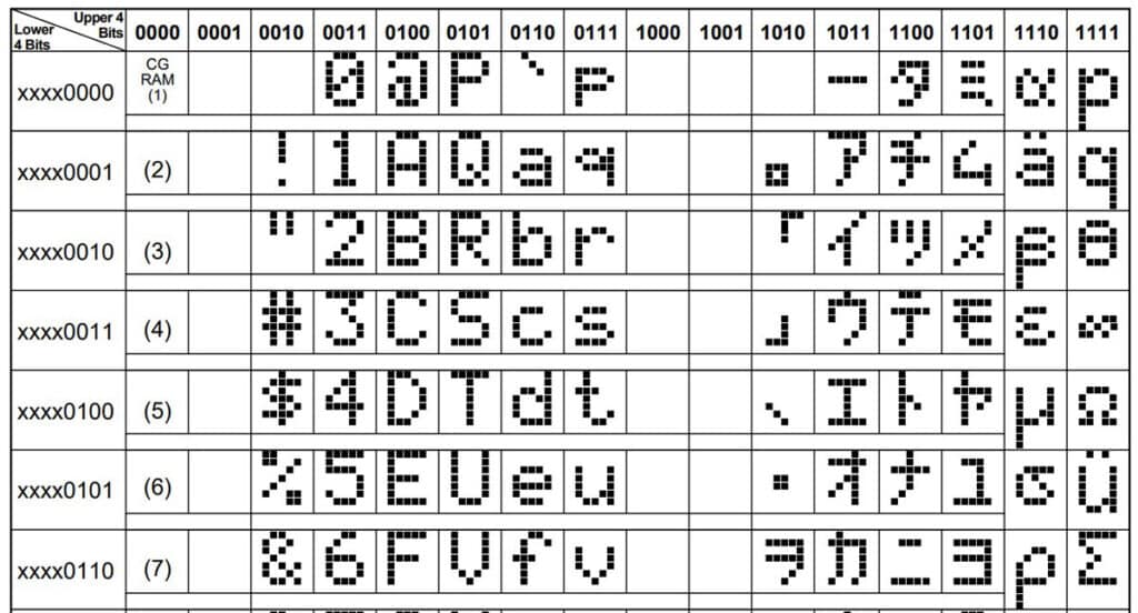
The LCD library takes care of mapping the right code from the ROM table.
But what if you want to create your characters like this one?
Or
That is where the CGRAM of the LCD controller comes into the picture. What is Character Generator RAM (CGRAM)?
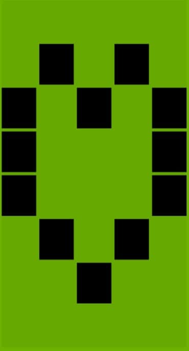
The LCD controller supports eight character fonts which you can define. Each character can be in 5×8 font.
One character on the LCD looks like this.
Each character is made up of 40 dots. 8 rows and 5 dots in each row.
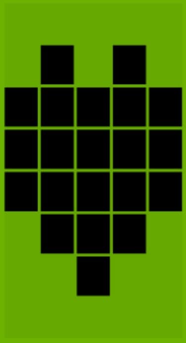
I will show you how to create the heart symbol
First, create a map as shown below. Wherever you want the dot to appear, write a 1. If you don’t want that particular cell in the LCD to be lit, write a zero. Refer to the image below.
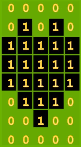
Next, create an array variable which will hold the values of each row as a number. I have created an array of type integer.
uint8_t heart[8] = {
  0b00000,
  0b01010,
  0b11111,
  0b11111,
  0b11111,
  0b01110,
  0b00100,
  0b00000,
};
Please make sure you have understood how I have defined the numbers. It is very convenient to represent the rows in binary as it also helps to edit and alter them for other symbols.
lcd.createChar(3, heart);
The above line will create a character defined by the array (in this case, it’s the heart )
The number 3 can be any number between 1 and 8. You can create up to eight custom characters.
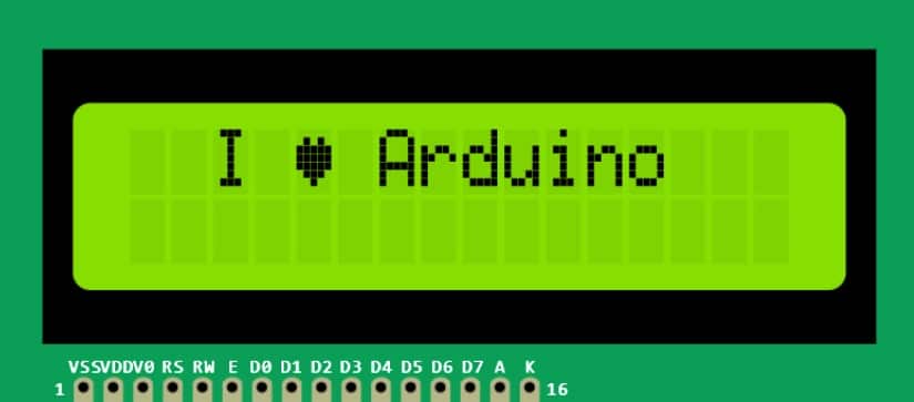
To print the newly created symbol on display, use the below code
lcd.print(" I \x03 Arduino");
The \x operation is a hexadecimal escape character which will be recognised by the library. It will now load the character stored in that location to the screen. Isn’t it cool?
Can you guess what the array should be to be set up for the below font?
Here is the array I used to create the symbol above.
uint8_t heart[8] = {
  0b00000,
  0b01010,
  0b10101,
  0b10001,
  0b10001,
  0b01010,
  0b00100,
  0b00000,
};
Now, I have combined those two symbols to create a beating heart symbol. You can find the code below.
// LCD1602 custom characters example
#include "LiquidCrystal_I2C.h"

LiquidCrystal lcd(12, 11, 10, 9, 8, 7);

uint8_t heart[8] = {
  0b00000,
  0b01010,
  0b10101,
  0b10001,
  0b10001,
  0b01010,
  0b00100,
  0b00000,
};

uint8_t heart2[8] = {
  0b00000,
  0b01010,
  0b11111,
  0b11111,
  0b11111,
  0b01110,
  0b00100,
  0b00000,
};

void setup() {
  lcd.createChar(4, heart);
  lcd.createChar(3, heart2);
  lcd.begin(16, 2);
  lcd.print("  I \x04 Arduino");
  lcd.print("  I \x03 Arduino");
}

void loop() {
  lcd.begin(16, 2);
  lcd.setCursor(0, 0);
  lcd.print("\x04");
  delay(500);
  lcd.setCursor(0, 0);
  lcd.print("\x03");
  delay(500);
}
I am hoping that this was very helpful to get insights about the custom characters.
FAQs About The ESP32 And I2C LCD Module Projects
I have included a list of the most frequently asked questions about projects built using ESP32 and the I2C LCD module. If you have more questions, please post them in the comments section. I will be glad to answer them.
1. What are the advantages of an I2C LCD with an ESP32?
You can reduce the wires required to connect the LCD to the ESP32. It means there is less scope for mistakes. You also free the number of GPIOs on ESP32, which you can further plan to use for other purposes. You can change the pins to which the SDA function is mapped in ESP32.
2. What common issues are faced when connecting I2C LCD with ESP32?
The I2C LCD and ESP32 may not work straightway due to several reasons. A few examples:
- I2C address of the LCD is not set correctly
- Wrong wiring
- Incompatible library
- Wrong pin mapping in the firmware, etc
3. Can I use multiple I2C devices with ESP32?
You can use multiple I2C devices with ESP32. You have t make sure no two I2C devices have the same address. There is a physical limit on the number of I2C devices you can connect (bus capacitance and clock speed). Generally, three to five devices can be easily connected without any issues.
4. How do I interface ESP32 with an I2C LCD?
Interfacing I2C LCD with an ESP2 is simple. You need to connect SDA and SCL lines to the appropriate pins of the I2C LCD device. You also have to install specific libraries later. Follow the previous sections above to learn and build an I2C LCD and ESP32 project.
5. What is an I2C LCD?
I2C LCD is a type of LCD that can be interfaced with microcontrollers over the I2C interface. The display will have an I2C device (slave) that accepts MCU commands over the I2C lines. The I2C interface reduces the number of wires needed to complete the connection.
Conclusión
In this article, I have covered all the essential information required to connect I2C LCD and ESP32.
Adding a display element to ESP32 will help in so many ways. You can eliminate mobile, computer, or other devices to understand what’s happening with your ESP32 data.
I have provided a step-by-step guide, connection diagrams, working ESP32 code, and FAQs about the project.
I’d love to hear from you! Let us know if there’s anything else you’d like me to cover in future articles or if I can do anything to improve this one.

I am Puneeth. I love tinkering with open-source projects, Arduino, ESP32, Pi and more. I have worked with many different Arduino boards and currently I am exploring, Arduino powered LoRa, Power line communication and IoT.