En este tutorial, aprenderás a utilizar un mando y un receptor IR con el Arduino. He incluido diagramas de cableado y varios códigos de ejemplo para ayudarte a empezar.
Siguiendo las instrucciones de este tutorial podrás utilizar prácticamente cualquier mando a distancia por infrarrojos (como el de tu televisor) para controlar cosas conectadas al Arduino.
In the code examples below, we will be using the IRremote Arduino library . This library is fairly easy to use and supports many different IR communication protocols. With the first two examples, you can identify the IR protocol of your remote and determine which code it sends when you press on a key/button. Next, I will show you how to map the received code to the key values and display these in the Serial Monitor or on an LCD. Lastly, we will look at controlling the outputs of the Arduino with an IR remote and receiver.
Suministros
Componentes de hardware
Software
Makerguides.com is a participant in the Amazon Services LLC Associates Program, an affiliate advertising program designed to provide a means for sites to earn advertising fees by advertising and linking to products on Amazon.com. As an Amazon Associate we earn from qualifying purchases.
¿Cómo funciona un mando y un receptor de infrarrojos (IR)?
Un mando a distancia y un receptor IR se comunican entre sí mediante la transmisión y descodificación de una señal en forma de radiación IR pulsada.
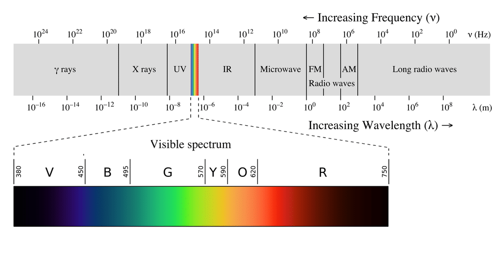
La radiación infrarroja (IR), o luz infrarroja, es un tipo de radiación electromagnética con longitudes de onda que van de 700 nm a 1 mm. Como el ser humano sólo puede ver la luz con longitudes de onda de aproximadamente 400 (violeta) a 700 (rojo) nanómetros, la radiación IR es invisible para el ojo humano.
Como la transmisión por infrarrojos es un protocolo inalámbrico basado en un tipo de luz, requiere una línea de visión clara entre el transmisor (el mando) y el receptor. Esto significa que no puede transmitir a través de paredes o techos, a diferencia del WiFi o el Bluetooth.
Fundamentos de la comunicación IR
Desgraciadamente, el LED IR del mando a distancia no es la única fuente de radiación IR. Cualquier objeto que tenga temperatura también irradia en el espectro infrarrojo. Este fenómeno también es utilizado por las cámaras térmicas para detectar el calor.
Toda esta IR ambiental puede interferir en la comunicación entre el mando y el receptor. Entonces, ¿cómo hace el receptor para detectar sólo la señal de infrarrojos procedente del mando? La respuesta es la modulación de la señal.
Con la modulación de la señal, la fuente de luz IR situada en el extremo del mando a distancia parpadea con una frecuencia determinada. En la electrónica de consumo, esta frecuencia portadora suele ser de unos 38 kHz.
Esta frecuencia específica se utiliza para la transmisión de IR comercial porque es poco frecuente en la naturaleza y, por tanto, puede distinguirse del IR ambiental.
The receiver is built in such a way that it only lets IR through that is coming in at 38 kHz. This is achieved using a bandpass filter and amplifier. The demodulated binary signal is then sent to the microcontroller (the Arduino) where it is decoded.
IR signal protocol
¿Qué aspecto tiene una señal de infrarrojos?
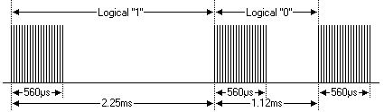
In the image above, the vertical axis can be seen as the voltage going to the IR LED in the remote and the horizontal axis is time. So when the IR LED is on, it is blinked (modulated) at 38 kHz and when it is off, no voltage is applied.
Lo importante es la cantidad de tiempo que el LED IR se mantiene alto o bajo (encendido o apagado). En el protocolo NEC, que es uno de los protocolos de transmisión IR más populares, los bits ("1" o "0") se representan de la siguiente manera:
Each bit consists of a 560 µs long 38 kHz carrier burst (about 21 cycles) followed by a pause. A logical “1” has a total transmission time of 2.25ms, while a logical “0” only 1.125 ms.
El tiempo que la señal permanece alta o baja y el número de bits que se envían para cada comando es diferente para todos los protocolos IR. En el protocolo NEC, el mensaje total suele constar de cuatro bytes de 8 bits.
Tipos de receptores IR
Los receptores de infrarrojos, a veces llamados sensores de infrarrojos o diodos de detección de infrarrojos, suelen tener dos formatos diferentes. Puedes comprar los diodos por separado o montados en una pequeña placa breakout.
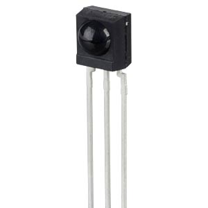
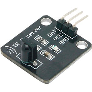
Funcionan exactamente igual, así que no importa cuál utilices. La única diferencia es que la placa de circuito impreso suele contener un pequeño LED que parpadea cada vez que el receptor detecta una señal, lo que puede ser útil para la depuración.
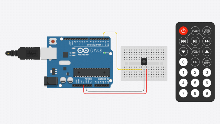
Conexión de un receptor de infrarrojos al Arduino
Es muy fácil conectar un receptor de infrarrojos al Arduino, ya que sólo hay que conectar tres cables. El cable de salida se puede conectar a cualquiera de los pines digitales del Arduino. En este caso, lo conecté al pin 2 para los primeros ejemplos de abajo.
La clavija de alimentación se conecta a 5 V y la clavija de tierra central a GND. Si utiliza un receptor montado en una placa de circuito impreso, compruebe las etiquetas de la PCB, ya que el orden de los pines puede ser diferente.
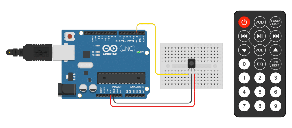
Las conexiones también se indican en la siguiente tabla
Conexiones del receptor IR
| Receptor IR | Arduino |
|---|---|
| OUT (izquierda) | Clavija 2 |
| GND (medio) | GND (-) |
| Vcc (derecha) | 5 V (+) |
Instalación de la biblioteca IRremote Arduino
For this tutorial, we will be using the popular IRremote library. This library is fairly easy to use and supports many different types of IR remotes.
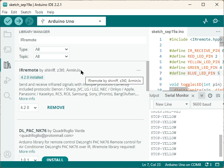
Para instalar la biblioteca, vaya a Herramientas > Gestionar Bibliotecas (Ctrl + Shift + I en Windows) en el IDE de Arduino. El Gestor de Bibliotecas se abrirá y actualizará la lista de bibliotecas instaladas.
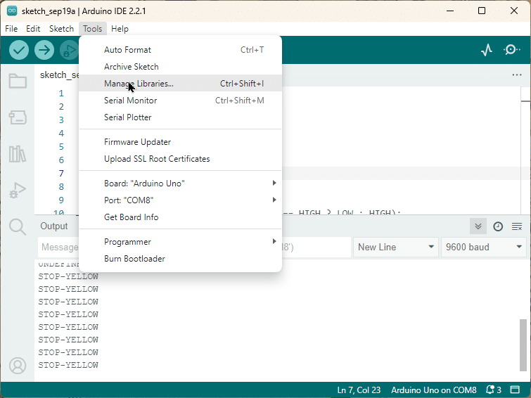
Puedes buscar 'IRremote' y buscar la biblioteca de shirriff y z3to. Seleccione la última versión y luego haga clic en Instalar.
Determine el protocolo IR utilizado por su mando a distancia
NEC es probablemente el protocolo de transmisión de infrarrojos más conocido y extendido, ya que es utilizado por la gran mayoría de los aparatos electrónicos de consumo fabricados en Japón. Sin embargo, existen muchos otros tipos de protocolos. Puede ser útil saber qué tipo de protocolo IR utiliza tu mando si quieres trabajar en proyectos más avanzados. O puede que simplemente tengas curiosidad
As of Sep 2023, the IRremote library supports the following IR protocols:
- PulseWidth
- PulseDistance
- Apple
- Denon
- JVC
- LG
- LG2
- NEC
- NEC2
- Onkyo
- Panasonic
- Kaseikyo
- Kaseikyo Denon
- Kaseikyo Sharp
- Kaseikyo JVC
- Kaseikyo Mitsubishi
- RC5
- RC6
- Samsung
- Samsung48
- SamsungLG
- Sharp
- Sony
- Bang&Olufsen
- BoseWave
- Lego
- MagiQuest
- Whynter
- FAST
With the short code below you can identify which protocol your remote is using. You can also try some other remotes that you have in your house and see if it can detect the protocol.
Localizador de protocolos a distancia por infrarrojos
#include "IRremote.hpp"

#define IR_RECEIVE_PIN 2

void setup() {
  Serial.begin(9600);
  IrReceiver.begin(IR_RECEIVE_PIN, ENABLE_LED_FEEDBACK);
}

void loop() {
  if (IrReceiver.decode()) {
    IrReceiver.printIRResultShort(&Serial);
    IrReceiver.resume();
  }
}
I experimented with three of the remotes in my house and two were detected as NEC, while the third one (for an air-conditioning unit) was UNKNOWN:
However, there is an excellent library called IRremoteESP8266, which specifically supports the protocols for various air-conditioners. So, if you want to control your air-conditioning unit vi IR, that’s the place to go but that is not the library we are using here.
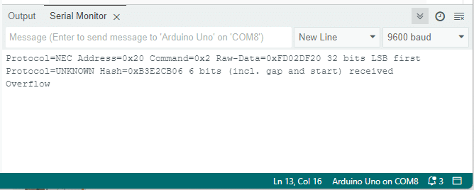
Note: for remotes with unknown protocols you will also see the “Overflow” error in addition to the protocol info. That is simply because the end of the IR command could not be detected, since the protocol was unknown.
Cómo encontrar los códigos de las llaves del mando a distancia
Because there are many different types of remotes on the market (with different number of keys and key functions), we need to determine which received signal corresponds to which key.
The IRremote library will read the signal and returns all information about the signal in the following structure:
struct IRData {
    decode_type_t protocol;          // UNKNOWN, NEC, SONY, RC5, PULSE_DISTANCE, ...
    uint16_t address;                // Decoded address
    uint16_t command;                // Decoded command
    uint16_t extra;
    uint16_t numberOfBits;           // Number of bits received for data
    uint8_t flags;                   // IRDATA_FLAGS_IS_REPEAT, IRDATA_FLAGS_WAS_OVERFLOW
    IRRawDataType decodedRawData;    // Up to 32  bit decoded raw data,
    uint32_t decodedRawDataArray[RAW_DATA_ARRAY_SIZE]; // 32 bit decoded raw data for send function.
    irparams_struct *rawDataPtr;     // Pointer of the raw timing data to be decoded.
};
We are especially interested in the command part of that structure. This will contain the code the remote sends depending on which key is pressed. By printing the command value in the Serial Monitor, we can create a conversion table.
The code below does just that. Note that we are adding a delay of 100ms, so that we slow down the printing if a key is pressed continuously, which will result in a repeated print out.
#include "IRremote.hpp"

#define IR_RECEIVE_PIN 2

void setup() {
  Serial.begin(9600);
  IrReceiver.begin(IR_RECEIVE_PIN, ENABLE_LED_FEEDBACK);
}

void loop() {
  if (IrReceiver.decode()) {
    uint16_t command = IrReceiver.decodedIRData.command;
    Serial.println(command);
    delay(100);  // wait a bit
    IrReceiver.resume();
  }
}
After you have uploaded the code, open the Serial Monitor. Now press each key on the remote and record the corresponding value that you see in the Serial Monitor.
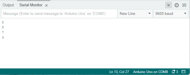
For my remote that controls an audio player, I got the following codes:
| Clave | Código |
|---|---|
| Play | 7 |
| Stop | 3 |
| Mute | 20 |
| Next track | 8 |
| Previous track | 2 |
| Volume up | 31 |
| Volume down | 23 |
Your table will probably look different! You will have to create your own to use the code examples below.
Print key names in the Serial Monitor
Now that we know which code corresponds to which keypress, we can modify the code to print the name of the pressed key in the Serial Monitor.
Para ello, utilizaremos una estructura de control de caso de conmutación. Esto nos permite ejecutar un trozo de código diferente dependiendo de la tecla que se pulse.
The code example below prints the key name in the Serial Monitor instead of the integer value like we did in the previous example. Note that we keep the delay, so that we don’t overwhelm the receiver with repeated signals when a key is pressed continuously.
#include "IRremote.hpp"

#define IR_RECEIVE_PIN 2

void setup() {
  Serial.begin(9600);
  IrReceiver.begin(IR_RECEIVE_PIN, ENABLE_LED_FEEDBACK);
}

void loop() {
  if (IrReceiver.decode()) {
    uint16_t command = IrReceiver.decodedIRData.command;
    switch (command) {
      case 7:
        Serial.println("PLAY");
        break;
      case 3:
        Serial.println("STOP");
        break;
      case 20:
        Serial.println("MUTE");
        break;
      case 8:
        Serial.println("NEXT");
        break;
      case 2:
        Serial.println("PREV");
        break;
      case 31:
        Serial.println("VOL+");
        break;
      case 23:
        Serial.println("VOL-");
        break;
      default:
        Serial.println("UNDEFINED");
    }

    delay(100);
    IrReceiver.resume();
  }
}
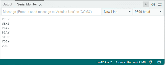
Here is what I see on the Serial Monitor when pressing some keys on my remote:
If your remote has different keys and sends different codes than the ones shown in the table above, simply replace the value and name of the lines in the switch case statement that looks like this:
 case 31:
   Serial.println("VOL+");
These lines translate to: when the command value is equal to 31, print “VOL+” in the Serial Monitor. If there is no case statement for a command value the default clause is activated and “UNDEFINED” is printed.
Cómo funciona el código
The first line of the code includes the IRremote.hpp library. This library provides the functions necessary to interact with IR signals.
#include "IRremote.hpp"
Next, we define the pin that will receive the IR signals. In this case, we’re using pin 2.
#define IR_RECEIVE_PIN 2
In the setup() function, we start serial communication at a baud rate of 9600. We also initiate the IR receiver on the pin we defined earlier, with LED feedback enabled. That means whenever a code is received an LED on the Arduino (and the IR receiver module) will flicker, which is handy for debugging.
void setup() {
  Serial.begin(9600);
  IrReceiver.begin(IR_RECEIVE_PIN, ENABLE_LED_FEEDBACK);
}
In the loop() function, we check if the IR receiver has decoded a signal. If it has, we get the command value from the decoded data.
void loop() {
  if (IrReceiver.decode()) {
    uint16_t command = IrReceiver.decodedIRData.command;
We then use a switch statement to interpret the command. Each case corresponds to a different command sent from the remote. For example, if the command is 7, the Arduino prints “PLAY” to the serial monitor.
    switch (command) {
      case 7:
        Serial.println("PLAY");
        break;
      case 3:
        Serial.println("STOP");
        break;
        ...

      case 23:
        Serial.println("VOL-");
        break;
      default:
        Serial.println("UNDEFINED");
    }
After interpreting the command, we delay for 100 milliseconds and then resume the IR receiver. This allows it to decode the next signal.
    delay(100);
    IrReceiver.resume();
  }
}
This code provides a basic framework for reading and interpreting signals from an IR remote. You can modify it to suit your specific needs.
Control remoto y receptor IR con Arduino y ejemplo de LCD
El siguiente ejemplo se puede utilizar para imprimir los valores de las teclas pulsadas en una pantalla LCD de caracteres. He escrito un tutorial detallado sobre el uso de pantallas LCD de caracteres que puede encontrar aquí:
Si prefiere utilizar una pantalla LCD I2C que necesite menos conexiones, consulte el tutorial que aparece a continuación:
Para este ejemplo, conecté la salida del receptor IR al pin digital 8 en lugar del 2. Las conexiones para la pantalla LCD de caracteres se muestran en el diagrama de cableado de abajo. Tenga en cuenta que también necesita un potenciómetro de 10 kΩ para ajustar el contraste de la pantalla y una resistencia de 220 Ω para controlar el brillo de la luz de fondo.
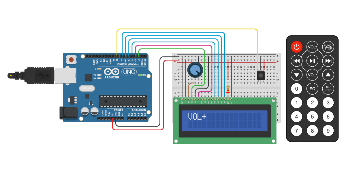
Las conexiones también se indican en la tabla siguiente. El pin más a la izquierda del LCD es el pin 1 (GND).
Conexiones del LCD y del receptor IR
| Pin | Conexión |
|---|---|
| Clavija 1 del LCD (GND) | Arduino GND |
| Clavija 2 del LCD (VCC) | Arduino 5 V |
| LCD pin 3 (VO) | Potenciómetro de clavija central |
| Potenciómetro del pin izquierdo | Arduino 5 V |
| Potenciómetro de clavija derecha | Arduino GND |
| LCD pin 4 (RS) | Arduino pin 2 |
| LCD pin 5 (RW) | Arduino GND |
| Clavija 6 del LCD (E) | Arduino pin 3 |
| Clavija 11 del LCD (DB4) | Arduino pin 4 |
| Clavija 12 del LCD (DB5) | Arduino pin 5 |
| Clavija 13 del LCD (DB6) | Arduino pin 6 |
| Clavija 14 del LCD (DB7) | Arduino pin 7 |
| Clavija 15 del LCD (ánodo del LED) | Arduino 5 V a través de una resistencia de 220Ω |
| Clavija 16 del LCD (LED-cátodo) | Arduino GND |
| Receptor IR OUT (izquierda) | Arduino pin 8 |
| Receptor IR GND (medio) | Arduino GND |
| Vcc del receptor IR (derecha) | Arduino 5 V |
Si tiene algún problema con la pantalla LCD, consulte este tutorial para obtener más detalles.
With the example code below, you can print the pressed key on the LCD.Again, if your remote sends different codes, just replace the command values and corresponding key values in the switch case statement.
Código de ejemplo de control remoto y receptor IR con Arduino y pantalla LCD
Puede copiar el código haciendo clic en el botón de la esquina superior derecha del campo de código.
#include "IRremote.hpp"
#include "LiquidCrystal.h"

// LCD object with pin parameters (RS, E, D4, D5, D6, D7)
LiquidCrystal lcd = LiquidCrystal(2, 3, 4, 5, 6, 7);

#define IR_RECEIVE_PIN 8

void setup() {
  lcd.begin(16, 2);  // LCD with 16 columns and 2 rows
  IrReceiver.begin(IR_RECEIVE_PIN, ENABLE_LED_FEEDBACK);
}

void loop() {
  if (IrReceiver.decode()) {
    uint16_t command = IrReceiver.decodedIRData.command;
    switch (command) {
      case 7:
        lcd.print("PLAY");
        break;
      case 3:
        lcd.print("STOP");
        break;
      case 20:
        lcd.print("MUTE");
        break;
      case 8:
        lcd.print("NEXT");
        break;
      case 2:
        lcd.print("PREV");
        break;
      case 31:
        lcd.print("VOL+");
        break;
      case 23:
        lcd.print("VOL-");
        break;
      default:
        lcd.print("UNDEFINED");
    }

    delay(100);
    IrReceiver.resume();
  }
}
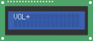
Debería ver la siguiente salida en la pantalla LCD si pulsa la tecla VOL+. Tenga en cuenta que es posible que tenga que ajustar el potenciómetro para aumentar el contraste de la pantalla.
Controla los LEDs (salidas de Arduino) con el mando y el receptor IR
Aunque es divertido ver los valores de las teclas en el Monitor Serial o en una pantalla LCD, probablemente querrás usar el control remoto para algo más útil, es decir, para controlar realmente algo. En el siguiente ejemplo, le mostraré cómo encender y apagar los LEDs con el control remoto. También puedes usar este tipo de código para controlar relés, luces y motores.
The code looks mostly the same as the previous examples but I added extra functionality to control the LEDs.
Tendrás que crear el siguiente circuito para controlar los LEDs:
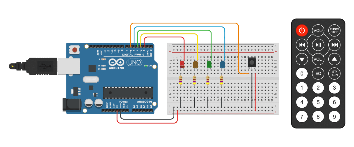
Los LEDs se conectan a los pines 2 a 5 del Arduino y la salida del receptor IR al pin 6. He utilizado unas resistencias de 470 Ω para limitar la corriente que pasa por los LEDs. La corriente de funcionamiento habitual de los LEDs de 3 y 5 mm es de unos 20 mA. Puedes determinar qué valor de resistencia necesitas con una calculadora online como ésta. A mí me gusta comprar estos surtidos de resistencias en Amazon para tener siempre a mano el valor adecuado.
#include "IRremote.hpp"

#define IR_RECEIVE_PIN 6
#define RED_LED_PIN 2
#define YELLOW_LED_PIN 3
#define GREEN_LED_PIN 4
#define BLUE_LED_PIN 5

void toggleLED(int pin) {
  digitalWrite(pin, digitalRead(pin) == HIGH ? LOW : HIGH);
}

void setup() {
  Serial.begin(9600);

  IrReceiver.begin(IR_RECEIVE_PIN, ENABLE_LED_FEEDBACK);

  pinMode(RED_LED_PIN, OUTPUT);
  pinMode(YELLOW_LED_PIN, OUTPUT);
  pinMode(GREEN_LED_PIN, OUTPUT);
  pinMode(BLUE_LED_PIN, OUTPUT);

  digitalWrite(RED_LED_PIN, LOW);
  digitalWrite(YELLOW_LED_PIN, LOW);
  digitalWrite(GREEN_LED_PIN, LOW);
  digitalWrite(BLUE_LED_PIN, LOW);
}

void loop() {
  if (IrReceiver.decode()) {
    uint16_t command = IrReceiver.decodedIRData.command;
    switch (command) {
      case 7:
        Serial.println("PLAY-BLUE");
        toggleLED(BLUE_LED_PIN);
        break;
      case 3:
        Serial.println("STOP-YELLOW");
        toggleLED(YELLOW_LED_PIN);
        break;
      case 20:
        Serial.println("MUTE-GREEN");
        toggleLED(GREEN_LED_PIN);
        break;
       default:
        Serial.println("UNDEFINED-RED");
        toggleLED(RED_LED_PIN);
    }

    delay(100);
    IrReceiver.resume();
  }
}
Explicación del código
First, we again include the IRremote.hpp library, which provides functions for working with IR remotes.
#include "IRremote.hpp"
Next, we define the pin numbers for the IR receiver and the LED pins. Note that we use a different pin (PIN 6) for the receiver than before (PIN 2).
#define IR_RECEIVE_PIN 6
#define RED_LED_PIN 2
#define YELLOW_LED_PIN 3
#define GREEN_LED_PIN 4
#define BLUE_LED_PIN 5
Then, we define a function called toggleLED that toggles the state of an LED pin. It takes an int parameter pin, which represents the pin number of the LED. If the pin is HIGH we set it to LOW and vice versa.
void toggleLED(int pin) {
  digitalWrite(pin, digitalRead(pin) == HIGH ? LOW : HIGH);
}
In the setup function, we initialize the serial communication at a baud rate of 9600. We also initialize the IR receiver and set the LED pins as output. Finally, we turn off all the LEDs.
void setup() {
  Serial.begin(9600);

  IrReceiver.begin(IR_RECEIVE_PIN, ENABLE_LED_FEEDBACK);

  pinMode(RED_LED_PIN, OUTPUT); // set the LED pins as output
  pinMode(YELLOW_LED_PIN, OUTPUT);
  pinMode(GREEN_LED_PIN, OUTPUT);
  pinMode(BLUE_LED_PIN, OUTPUT);

  digitalWrite(RED_LED_PIN, LOW); // turn all the LEDs off
  digitalWrite(YELLOW_LED_PIN, LOW);
  digitalWrite(GREEN_LED_PIN, LOW);
  digitalWrite(BLUE_LED_PIN, LOW);
}
In the loop function, we check if the IR receiver has received a signal. If a signal is received, we extract the command from the decoded IR data. Based on the command, we perform different actions.
void loop() {
  if (IrReceiver.decode()) {
    uint16_t command = IrReceiver.decodedIRData.command;
    switch (command) {
      case 7:
        Serial.println("PLAY-BLUE");
        toggleLED(BLUE_LED_PIN);
        break;
      case 3:
        Serial.println("STOP-YELLOW");
        toggleLED(YELLOW_LED_PIN);
        break;
      case 20:
        Serial.println("MUTE-GREEN");
        toggleLED(GREEN_LED_PIN);
        break;
      default:
        Serial.println("UNDEFINED-RED");
        toggleLED(RED_LED_PIN);
    }

    delay(100);
    IrReceiver.resume();
  }
}
In this code snippet, we have three cases for different commands received from the IR remote. If the command is 7, we print “PLAY-BLUE” to the serial monitor and toggle the blue LED. For command 3, we print “STOP-YELLOW” and toggle the yellow LED. And for command 20, we print “MUTE-GREEN” and toggle the green LED. For any other command, we print “UNDEFINED-RED” and toggle the red LED.
After performing the necessary actions, we add a delay of 100 milliseconds and resume the IR receiver to listen for the next signal.
Conclusión
En este tutorial, te he mostrado cómo utilizar un mando y un receptor IR con Arduino. Hemos visto diferentes ejemplos de código para determinar el protocolo IR e identificar los códigos de las teclas IR para su control remoto. Luego vimos cómo mostrar los valores de las teclas/botones en el Monitor Serial y en una pantalla LCD de 16×2 caracteres. Por último, le mostré cómo controlar las salidas del Arduino con el control remoto para encender y apagar algunos LEDs. Hay muchas más aplicaciones para los receptores IR y los mandos a distancia, así que asegúrate de dejar algunas sugerencias en los comentarios.
Espero que este artículo te haya resultado útil e informativo. Si lo has hecho, ¡compártelo con un amigo al que también le guste la electrónica y hacer cosas!
I would love to know what projects you plan on building (or have already built) with an IR remote and receiver. If you have any questions, suggestions, or if you think that things are missing in this tutorial, please leave a comment below.
Other Useful Links From Around The Web
- Arduino-IRremote
- IRremote – Arduino Reference
- Arduino Infrared Remote Tutorial : 7 Steps
- How to Set Up an IR Remote and Receiver on an Arduino
- Arduino IR Remote Controller Tutorial
- Arduino – Control LED’s with IR Remote Control
- IR Remote Control | Arduino Tutorial
Benne is professional Systems Engineer with a deep expertise in Arduino and a passion for DIY projects.
Vinayak
Monday 8th of January 2024
Dont need to use any specific remote. Any simple TV remote will also work
Stefan Maetschke
Monday 8th of January 2024
Yes, that is correct. Almost any TV remote should work. Garage openers are different.
boB
Thursday 14th of September 2023
I decoded and wrote code to mimic the Disney monorail model since this one was not in the library. The latest model has an 8 bit pulse code, the previous model is 9 bits and must be repeated at least three times.
Harry
Tuesday 12th of September 2023
Thanks, that was helpful, but as others say, you should update the sample code a bit. :)
Stefan Maetschke
Tuesday 19th of September 2023
Thanks for the feedback. The code has been updated.
Mike Sims
Wednesday 31st of August 2022
Hola,
So its been a while since you wrote this guide. And the IrRemote library has changed significantly some time ago... I re-wrote the first sketch in this guide so that it works with the new changes in the library - which are significant and require re-writing your code because, from the version of the library you use here, the author of the library has not maintained backward compatibility. So copying your code from here and trying to use it on the latest version of the library simply will not work... the code will not compile.
Anyways, here is the first sketch in this guide re-written for the latest version of the library. I tested it and it works:
``` #include #include // include the IRremote library
#define IR_RECEIVE_PIN 2 // define the IR receiver pin
void setup() { Serial.begin(9600); // begin serial communication with a baud rate of 9600 pinMode(LED_BUILTIN, OUTPUT); IrReceiver.begin(IR_RECEIVE_PIN, ENABLE_LED_FEEDBACK); }
void loop() { if (IrReceiver.decode()) { String commandData = String(IrReceiver.decodedIRData.decodedRawData, HEX); commandData.toUpperCase(); String protocol = getProtocolString(IrReceiver.decodedIRData.protocol); Serial.println(commandData + ": " + protocol); IrReceiver.resume(); } } ```
tim lee
Thursday 14th of April 2022
gave me the error code "'SANYO' was not declared in this scope" for the first bit of code, why?
Mike Sims
Wednesday 31st of August 2022
@tim lee, There have been a lot of changes implemented in the library since this guide was written ... see this portion of the readme for conversion from 2.x to 3.x https://github.com/Arduino-IRremote/Arduino-IRremote#converting-your-2x-program-to-the-3x-version