El JSN-SR04T es un sensor de distancia por ultrasonidos fácil de usar y resistente al agua con un alcance de 25 a 450 cm. Si está planeando construir un sistema de medición del nivel del agua o si necesita realizar otras mediciones de distancia en el exterior, ¡este es el sensor que necesita!
En este artículo, he incluido un diagrama de cableado y códigos de ejemplo para que puedas empezar a experimentar con tu sensor. Después de cada ejemplo, desgloso y explico cómo funciona el código, por lo que no deberías tener problemas para modificarlo y adaptarlo a tus necesidades.
First, we will look at an example that doesn’t use an Arduino library. Next, I will cover the easy to use NewPing library that has some nice built-in features. In the last, example I will show you how to display the measured distances on a 4-Digit-Display.
But let’s get started with the parts you will need to build this project.
Required parts
Below you will find the parts required for this project. When looking for the JSN-SR04T, you might come across the updated version, the JSN-SR04T-2.0. This newer version works exactly the same but is rated for 3-5 V instead of 5 V. However, some users have found issues while using the sensors at a lower voltage. Using a longer trigger pulse of at least 20 µs instead of 10 µs seems to help if you are having faulty readings.

Arduino Uno

USB Cable for Arduino UNO

Dupont Wire Set

Tablero de pruebas
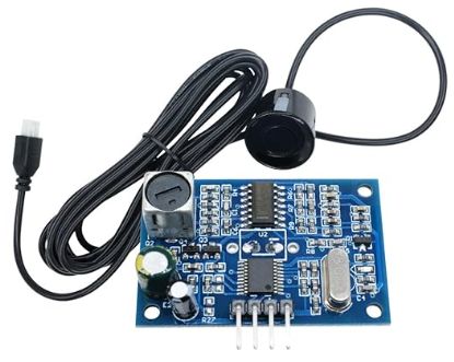
JSN-SR04T Sensor
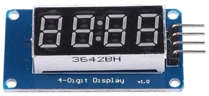
4-Digit-Display TM1637
Makerguides.com is a participant in the Amazon Services LLC Associates Program, an affiliate advertising program designed to provide a means for sites to earn advertising fees by advertising and linking to products on Amazon.com. As an Amazon Associate we earn from qualifying purchases.
About the JSN-SR04T Sensor
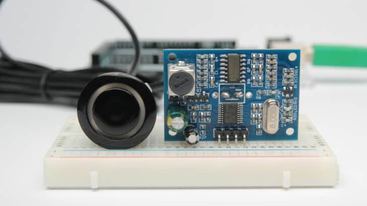
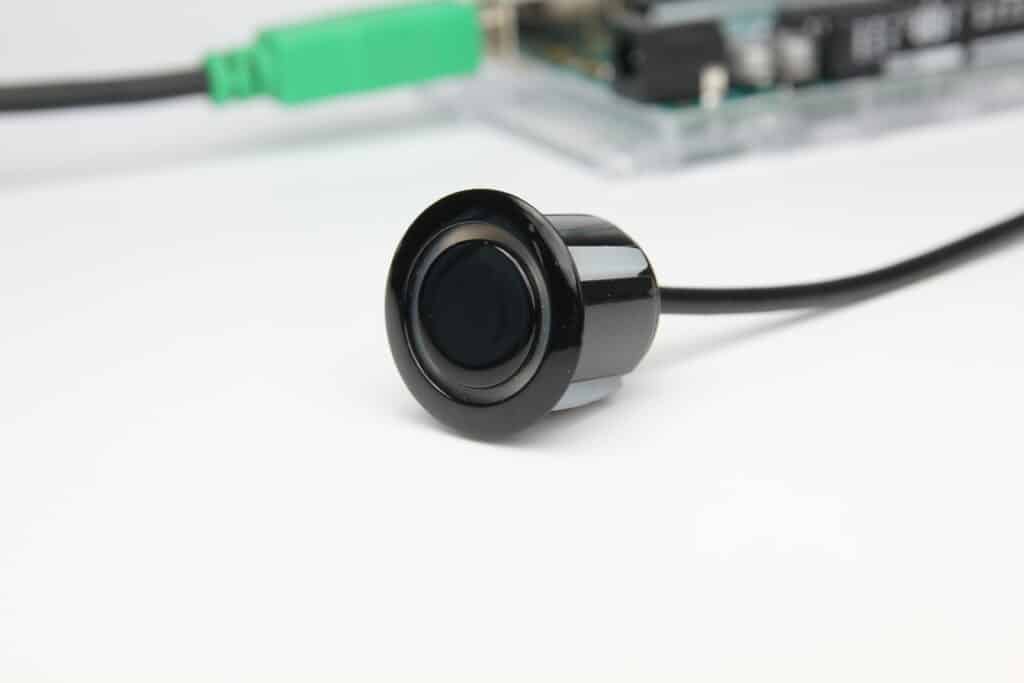
The sensor comes with a 2.5 m long cable that connects to a breakout board which controls the sensor and does all the processing of the signal. Note that only the sensor and the cable itself are waterproof. Don’t immerse the breakout board itself in water!
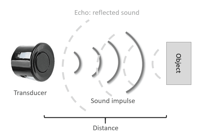
Un sensor de distancia por ultrasonidos funciona enviando ondas ultrasónicas. Estas ondas de ultrasonido son reflejadas por un objeto y el sensor ultrasónico las detecta. Al cronometrar el tiempo transcurrido entre el envío y la recepción de las ondas sonoras, se puede calcular la distancia entre el sensor y un objeto.
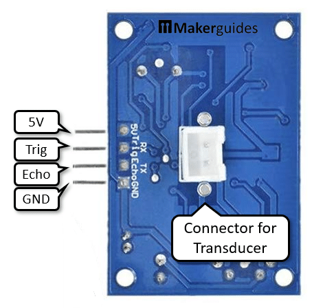
Pinout of JSN-SR04T
The breakout board of of JSN-SR04T the has four pins. 5V y GND for the power supply, Trig to trigger sending the ultrasound impulse and the output Echo, which returns a pulse that is proportional in length to the measured distance. The picture below shows the pinout.
Function of JSN-SR04T
To operate the sensor, you have the set Trig to HIGH for at least 10 microseconds. This will cause the board to send eight ultrasonic impulses (sonic burst).
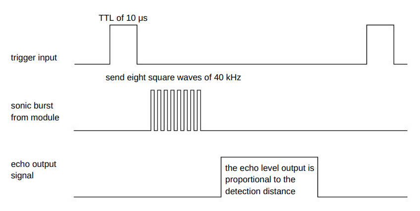
If a reflected sound (echo) is received the Echo output will go HIGH level and the distance can be calculated as
distance = high level time * 340 m/s / 2
where 340m/s is the speed of sound. We will use this formula later in our code but since we are going to measure the distance in cm, the constant will be 0.034cm/s.
Note that ultrasonic sensors are not like lasers with a focused beam. Instead their directivity is shaped like a bubble and also requires a sufficiently large and hard/reflective surface for accurate distance measurements.
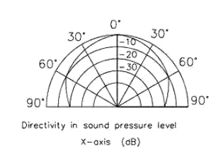
In case of the JSN-SR04T, the target should be at least 0.5 square metres in size and you want to point the sensor perpendicular to the target. The table below shows the specification of the sensor but be beware that measuring range and resolution assume ideal conditions.
Especificaciones del JSN-SR04T
| Tensión de funcionamiento | 5 V |
| Corriente de trabajo | 30 mA |
| Corriente de reposo | 5 mA |
| Frecuencia | 40 kHz |
| Rango de medición | 25-450 cm |
| Resolución | 2 mm |
| Ángulo de medición | 45-75 grados |
| Dimensiones del sensor | 23,5 x 20 mm, cable de 2,5 m de longitud |
| Dimensiones de la placa de circuito impreso | 41 x 28,5 mm |
| Agujero de montaje | 18 mm |
Para más información, puede consultar la hoja de datos aquí.
JSN-SR04T vs HC-SR04
What are the differences between this sensor and the HC-SR04? The main difference, besides it being waterproof, is that this sensor uses only one ultrasonic transducer instead of two. This transducer serves as both the transmitter and the receiver of the ultrasound waves.
For more info on how ultrasonic sensors work, you can check out my article on the HC-SR04. In this article the working principles of an ultrasonic distance sensor are explained in greater detail.
Wiring – JSN-SR04T to Arduino
El diagrama/esquema de cableado de abajo muestra cómo conectar el sensor JSN-SR04T al Arduino. La placa de circuito impreso del JSN-SR04T tiene exactamente la misma distribución de pines que el HC-SR04, por lo que se puede utilizar como un reemplazo. El cable del sensor se puede conectar al conector de la parte posterior de la placa de circuito impreso.
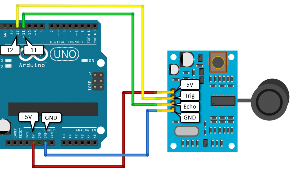
The code examples below use digital pin 12 and 11 for the trigger and echo pin, but of course you can change this to any digital pin you want.
| 5 V | 5 V |
| Trig | Clavija 12 |
| Eco | Clavija 11 |
| GND | GND |
Código de ejemplo para el sensor JSN-SR04T con Arduino
Ahora que has cableado el sensor es el momento de conectar el Arduino al ordenador y cargar algo de código. El sensor se puede utilizar sin una biblioteca de Arduino. Más adelante te mostraré un ejemplo con la librería NewPing, que hace el código mucho más corto.
Upload the following example code to your Arduino using the Arduino IDE. This code works for the JSN-SR04T-2.0 too. In the following sections, I will explain how the code works in detail.
const int trigPin = 12;
const int echoPin = 11;
void setup() {
Serial.begin(115200);
pinMode(trigPin, OUTPUT);
pinMode(echoPin, INPUT);
}
void loop() {
digitalWrite(trigPin, LOW);
delayMicroseconds(5);
digitalWrite(trigPin, HIGH);
delayMicroseconds(10);
digitalWrite(trigPin, LOW);
long duration = pulseIn(echoPin, HIGH);
long distance = duration * 0.034 / 2;
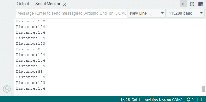
Serial.print("Distance:");
Serial.println(distance);
delay(100);
}
If you run the code and point the sensor to objects in different distances, you should varying distances (in cm) appear on the Serial Monitor. Don’t forget to set the baud rate to 115200 for this example!
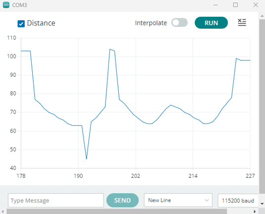
You can also open the Serial plotter and should see a wavy line if you move the sensor around to measure various distances.
Cómo funciona el código
En primer lugar, se definen el pin de disparo y el pin de eco. Los llamo trigPin y echoPin. The trigger pin is connected to digital pin 12 and the echo pin to digital pin11 on the Arduino. The statement const is used to give a name to a constant value.
const int trigPin = 12;
const int echoPin = 11;
En el setup(), you start by initializing the serial communication at a baud rate of 115200. To display the measured distance in the serial monitor, press Ctrl+Shift+M or Tools > Serial Monitor. Make sure the baud rate is also set to 115200 in the serial monitor.
Next, we are setting the trigPin as an output and the echoPin as an input.
void setup() {
  Serial.begin(115200);
  pinMode(trigPin, OUTPUT);
  pinMode(echoPin, INPUT);
}
En el loop()En el caso de que el sensor se dispare, se debe poner el trigPin en HIGH durante 20 µs. Tenga en cuenta que para obtener una señal limpia debe empezar por despejar el trigPin poniéndolo en LOW durante 5 microsegundos.
void loop() {
  digitalWrite(trigPin, LOW);
  delayMicroseconds(5);

  digitalWrite(trigPin, HIGH);
  delayMicroseconds(10);
  digitalWrite(trigPin, LOW);
Next, you need to read the duration of the pulse sent by the echoPin. I use the function pulseIn() para esto. Esta función espera que el pin pase de LOW a HIGH, inicia la temporización, luego espera que el pin pase a LOW y detiene la temporización.
After that, you can calculate the distance by using the formula mentioned in the introduction of this tutorial. Note that we use a constant of 0.034 for the speed of sound (instead of 340), since we want the distance in centimetres and not in meters.
  long duration = pulseIn(echoPin, HIGH);
  long distance = duration * 0.034 / 2;
Finally, print the calculated distance in the serial monitor and also show in in the plotter. The delay of 100 milliseconds at the end slows the measurements down to a reasonable rate.
  Serial.print("Distance:");
  Serial.println(distance);
  delay(100);
Código de ejemplo JSN-SR04T con Arduino y la biblioteca NewPing
La librería NewPing escrita por Tim Eckel puede utilizarse con muchos sensores de distancia ultrasónicos. La última versión de esta biblioteca se puede descargar aquí en bitbucket.org. Puedes notar que el código de abajo, que usa la librería NewPing, es mucho más corto que el código que usamos antes.
Puedes instalar la librería yendo a Sketch > Include Library > Add .ZIP Library en el IDE de Arduino.
La librería incluye algunos ejemplos que puedes usar, pero tendrás que modificarlos para que coincidan con tu configuración de hardware. He incluido un código de ejemplo modificado a continuación que se puede utilizar con la misma configuración de cableado que antes.
#include "newping.h"

const int trigPin = 12;
const int echoPin = 11;
const int maxDist = 450;

NewPing sonar(trigPin, echoPin, maxDist);

void setup() {
  Serial.begin(115200);
}

void loop() {
  // Wait 50ms between pings (about 20 pings/sec)
  delay(50);

  long distance = sonar.ping_cm();

  Serial.print("Distance:");
  Serial.println(distance);
  delay(100);
}
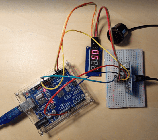
Example: JSN-SR04T with Arduino and 4-Digit-Display
As a last example, I want to show you how to display the measured distances on a 4-Digit 7-Segment Display. The display, listed under required parts, has a TM1637 driver, which makes it very easy to connect and to control. Let’s start with the wiring of this display in addition to the sensor.
Wiring – JSN-SR04T to Arduino and 4-Digit Display
We will wire the JSN-SR04T sensor the same as before but use the breadboard in addition to distribute the power to the sensor and the display.
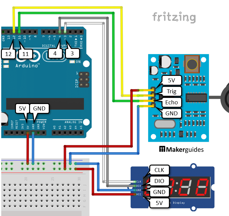
The display receives its power (VSS, GND) from the breadboard and has two extra pins that you need to connect to the Arduino. Connect the CLK (Clock) pin to pin 3 of the Arduino (white wire) and the DIO (Digital IO) to pin 4 of the Arduino (gray wire). And that completes the wiring.
Now, let’s have a look at the code.
Code – JSN-SR04T with Arduino and 4-Digit Display
We keep the code relating to the JSN-SR04T sensor as it is. As before we use the NewPing library, initialized with the same pins, and read distances via sonar.ping_cm().
#include "NewPing.h"
#include "TM1637Display.h"

// Display
const int clkPin = 3;
const int dioPin = 4;

// Sonar
const int trigPin = 12;
const int echoPin = 11;
const int maxDist = 450;

NewPing sonar(trigPin, echoPin, maxDist);
TM1637Display display = TM1637Display(clkPin, dioPin);

void setup() {
  Serial.begin(115200);
  display.setBrightness(5);
}

void loop() {
  long distance = sonar.ping_cm();
  Serial.print("Distance:");
  Serial.println(distance);
  display.showNumberDec(distance);
  delay(200);
}
What is new, is that we create the display TM1637Display object. It is initialized with the clkPin y dioPin constants, which are the pins we connected the display to.
En el setup() function, we set the brightness of the display, with 0 being the lowest brightness and being 7 the highest brightness. This command also turns the display on.
Finally, in the loop() function, we simply display the measured distance by calling display.showNumberDec(distance). And that’s it. Now you have an ultrasonic distance measure that displays distances in centimetres on a 4-digit display.
Conclusión
En este artículo, te he mostrado cómo funciona el sensor de distancia ultrasónico JSN-SR04T y cómo puedes utilizarlo con Arduino. Espero que te haya resultado útil e informativo. Si lo has hecho, ¡compártelo con un amigo al que también le guste la electrónica!
Me encantaría saber qué proyectos planeas construir (o ya has construido) con este sensor. Si tienes alguna pregunta, sugerencia, o si crees que faltan cosas en este tutorial, por favor deja un comentario abajo.
Links
Si quiere saber más sobre otros sensores de distancia, los siguientes artículos pueden resultarle útiles:
- Cómo utilizar un sensor de distancia IR SHARP GP2Y0A21YK0F con Arduino
- Cómo utilizar un sensor de distancia IR SHARP GP2Y0A710K0F con Arduino
- Cómo utilizar un sensor de distancia ultrasónico HC-SR04
- Tutorial del sensor de distancia resistente a la intemperie MaxBotix MB7389
- Tutorial Arduino del sensor de distancia ultrasónico MaxBotix MB1240
Benne is professional Systems Engineer with a deep expertise in Arduino and a passion for DIY projects.
ARJUN M
Wednesday 24th of May 2023
Hello, Iam working with this sensor for my project water level indicator , Iam struggling to make this sensor beam width as linear manner ,so i f any know about this idea please help out of this. And also one more problem that iam facing iam trying to visualizing the ultrasonic sensor path.....
Ángel Pedroza
Jueves 18 de agosto de 2022
Una muy buena forma de explicación. Realmente comentas cada código y al final la comparativa que realizas es realmente muy buena. Gracias por tomarte el tiempo de escribirlo. Muchas felicidades.
Saludos desde Aguascalientes, México
Mi sitio
Sábado 23 de julio de 2022
Un sitio web estupendo
Increíble blog gracias por compartir hoy en este blog
Steve
Domingo 20 de marzo de 2022
Hola, gracias por los detalles. He sido capaz de configurar esto para medir las nevadas. Estoy recibiendo lecturas precisas cuando no hay nieve y soy capaz de obtener una lectura precisa después de la nieve se hace, y por lo tanto puede determinar fácilmente la cantidad de nieve ha caído restando los 2. Lo que estoy luchando con ahora, es cuando la nieve está cayendo - mis lecturas son "salvaje y loco". Supongo que la causa es que el sensor está reflejando los copos de nieve que se encuentran bajo el sensor en función de cada lectura. Supongo que no hay manera de resolver esto, pero quería ver si alguien tenía alguna idea para hacer frente a esto? Aprecio cualquier y todas las sugerencias.
Bhaaskar Rajarajan
Viernes 18 de junio de 2021
Hola
Muy buena explicación.
1) Me gustaría saber cómo utilizar este sensor con sistema de tres hilos echo y trigger pin en el mismo I/O Es necesario conectar algún componente. He leído en alguna parte en la web. Hay que conectar una resistencia de 2K2 entre los pines Echo y Trigger. Si es así en que pin I / O para ser conectado
2) Como usted dijo, el sensor que se utiliza en el tubo estrecho para medir en el tanque de agua, ¿cuál es el tamaño del tubo (pulgadas)
esperando su respuesta
Gracias y saludos
Bhaaskar R