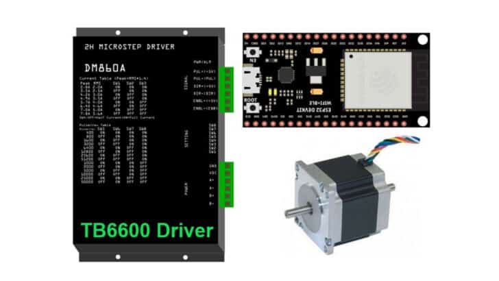
A stepper motor driver such as the TB6600 is straightforward and quick to set up.
In this article, I will take you through all the essential information you need to know to use a TB6600 stepper motor driver with an ESP32.
I will show you the connections needed between the ESP32 and TB6600 to complete a working project. I have covered the necessary setting information to ensure you drive the stepper motor with the correct TB6600 configuration.
You will find how to configure TB6600 to suit different current levels and a different micro-stepping mode supported by the TB6600.
I have also collected the most frequently asked questions on the ESP32 and TB6600 projects. Let’s get started!
(I also have an article on How To Use the TB6600 Stepper Motor Driver with Arduino if you want to work with an Arduino microcontroller instead.
Components Needed To Build ESP32 And TB6600 Stepper Motor Driver
Hardware Components
- Dupont wire x 1 set
- Micro USB Cable for ESP32 (for powering Arduino and programming) x 1
Software
Guide
Makerguides.com is a participant in the Amazon Services LLC Associates Program, an affiliate advertising program designed to provide a means for sites to earn advertising fees by advertising and linking to products on Amazon.com.
Basics of The ESP32 And TB6600 Stepper Motor Driver
Stepper Motor Fundamentals
In this section, we will understand the basics of the stepper motor and TB6600 stepper motor driver.
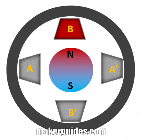
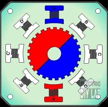
The above image is a simplified presentation of how a stepper motor works. Assume there is a magnet in the centre. I have marked the north and south poles. The four coils are labelled A, B, A’, and B’.
Now, when nothing is being driven, the magnet stays in place as no force is acting on it due to the 4 coils.
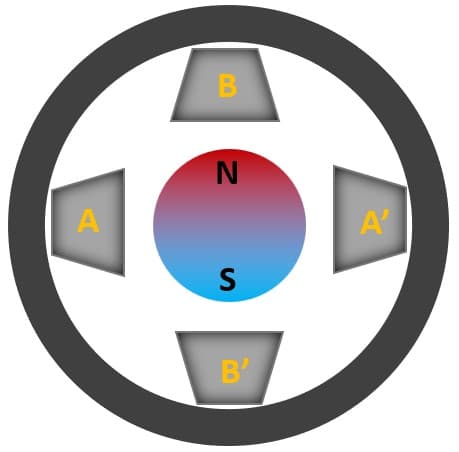
To start motion, let’s energize one of the coils. The coil temporarily acts as a magnet when a current flows through it. In the image above, I have excited coil A.
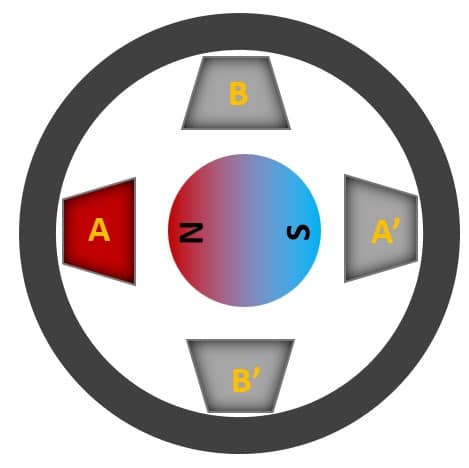
Notice how the magnet aligns north with coil A. If you change the excitations orderly, i.e., A → B → A’ → B’, you can make the motor clockwise. If you reverse the logic, i.e., A →B’ → A’ → B, the motor turns anticlockwise.
I hope my simplified explanation was easy to comprehend.
In practical stepper motors, there will be not just 4 but many more such coils which provide precise movements.
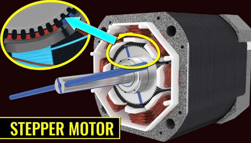
You can see in the image above what an actual stepper motor would look like. A 200-step stepper motor means there will be 200 such coils set up in an orderly fashion which can provide smaller steps of rotation.
One revolution means it is 360°. If a stepper motor has 200 steps, it means you can cover 360° / 200 steps or 1.8°.
Here is another animation of the stepper motor.
Introduction to TB6600
Driving a stepper motor manually is difficult. It would help if you controlled many things. So, it is permanently done using a dedicated driver IC.
One such driver IC is TB6600. It is a famous one among hobbyists and professionals both.
Here is the datasheet of TB6600.
Let’s understand the features and capabilities of the TB6600 stepper motor driver.
Features of TB6600 Stepper Motor Driver
TB6600 supports 8 levels of current control. Current levels supported – 0.5 A, 1 A, 1.5 A, 2 A, 2.5 A, 3 A, 3.5 A.
What are these current levels?
Since TB6600 is a generic stepper motor driver, you must set the maximum current based on the stepper motor you are using.
For example, if the stepper motor is rated to 1.2 A, then the current limit must be less than or equal to 1.2 A. Then you should set the current limit to 1 A or less.
How do you set the current?
You should set the switches S4, S5 and S6 as per the table below. Since we want to set the current limit to 1 A, the switches should be set as follows.
( S4, S5, S6 ) → ( ON, ON, OFF )
| Current | S4 | S5 | S6 |
| 0.5 A | ON | ON | ON |
| 1 A | ON | ON | OFF |
| 1.5 A | ON | OFF | ON |
| 2 A | ON | OFF | OFF |
| 2.5 A | OFF | ON | ON |
| 2.8 A | OFF | ON | OFF |
| 3 A | OFF | OFF | ON |
| 3.5 A | OFF | OFF | OFF |
Where are these switches?
The switches are present in the side panel of the TB6600 module.
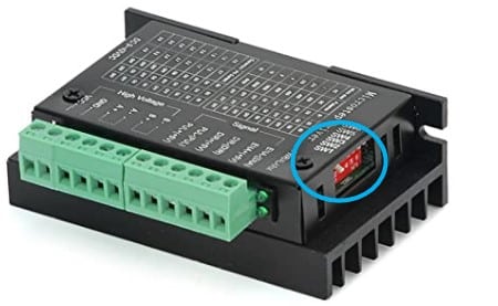

I hope the image will help you to locate the switches faster.
The second feature is micro-level adjustment settings. You can set 7 levels of micro-step adjustment.
Please refer to the table below to understand the settings.
| Microstep | Pulse/Rev | S1 | S2 | S3 |
| NC | NC | ON | ON | ON |
| 1 | 200 | ON | ON | OFF |
| 2/A | 400 | ON | OFF | ON |
| 2/B | 400 | OFF | ON | ON |
| 4 | 800 | ON | OFF | OFF |
| 8 | 1600 | OFF | ON | OFF |
| 16 | 3200 | OFF | OFF | ON |
| 32 | 6400 | OFF | OFF | OFF |
What does micro-stepping mean?
Microstepping is used in stepper motors to achieve smoother and more precise motor movement control.
Traditional stepper motors rotate in discrete steps, with each step representing a fixed angular displacement.
Micro-stepping divides these discrete steps into smaller angular increments, which allows the motor to move more smoothly and precisely.
How does it work?
By varying the current levels in a controlled manner, the motor can be moved in tiny increments, resulting in smoother motion and more precise positioning.
Microstepping is commonly used in applications requiring high accuracy.
Step-angle = Motor Step Angle / Micro step
A few examples:
- A stepper motor with a 1.8° step angle (200 steps), the final step angle under “Micro step 4”, will be 1.8° / 4 = 0.45°.
- A stepper motor with a 1.8° step angle (200 steps), the final step angle under “Micro step 2”, will be 1.8° / 2 = 0.90°.
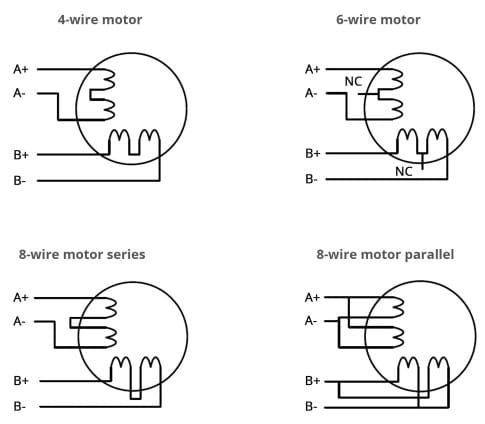
You may come across several types of motors. You can easily connect 4-wire, 6-wire, and 8-wire motors to the TB6600 driver module. Follow the pin connection guide below.
The TB6600 also has several advanced features including a large area heat sink to dissipate heat effectively, strong anti-high-frequency interference ability, input anti-reverse protection, and protection against overheat, overcurrent, and short circuits.
Control Signal Description of TB6600
The pin description of the TB6600 module is given in the table below.
| Pin name | Description |
| PUL+ | Step pulse signal positive input |
| PUL- | Step pulse signal negative input |
| EN+ | Offline enable signal positive input |
| EN- | Offline enable signal negative input |
| DIR+ | Stepping direction input positive |
| DIR- | Stepping direction input negative |
| A+ | Stepper motor A+ Connection |
| A- | Stepper motor A- Connection |
| B+ | Stepper motor B+ Connection |
| B- | Stepper motor B- Connection |
| DC+ | Power supply positive |
| DC- | Power supply negative |
Power Supply Requirements of TB6600
You can power up TB6600 with a power supply ranging from 9 V up to 42 V. A standard wall adapter of 12 V is a good power supply.
The current consumption depends on the motor connections and the load the motor is driving.
Step-By-Step Instructions To Connect The TB6600 Module with ESP32
In this section, we will build a project using ESP32 and the TB6600 Stepper motor driver.
Let’s get started with the hardware connections!
Step 1: Complete the GPIO connections between the ESP32 and TB6600
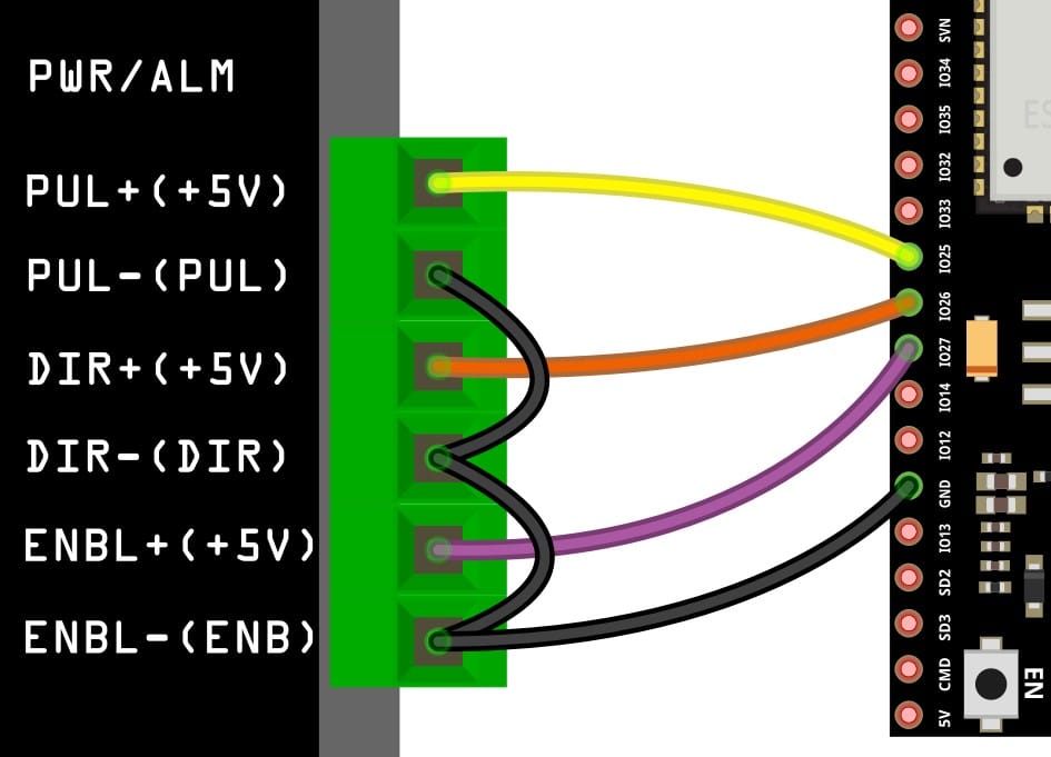
Connect the GND pin of the ESP32 module to the GND of the TB6600. Choose any GND pins available on the ESP32 for the connection. It is an excellent practice to start with the GND connections.
You can use the ESP32’s GPIO25, GPIO26, and GPIO27 for the rest of the TB6600 stepper motor driver connections, as shown in the image above.
Step 2: Connect the stepper motor
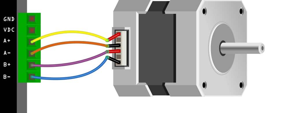
Follow the diagram above to complete the connection between the stepper motor and the TB6600 stepper motor driver IC.
Step 3: Complete connection
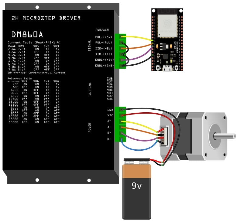
You can connect the power once you have completed programming the ESP32 provided in the next section. Congratulations, that completes the hardware connections.
ESP32 Code Example For TB6600 Stepper Motor Project
In this section, you can find the complete ESP32 code to test the TB6600 connections.
Please follow the instructions in the guide to install the ESP32 core on Arduino IDE.
 int PUL = 25; //define Pulse pin
int DIR = 26; //define Direction pin
int ENA = 27; //define Enable Pin
void setup() {
  pinMode (PUL, OUTPUT);
  pinMode (DIR, OUTPUT);
  pinMode (ENA, OUTPUT);
}

void loop() {
  for (int i = 0; i < 6400; i++) // Forward 5000 steps
  {
    digitalWrite(DIR, LOW);
    digitalWrite(ENA, HIGH);
    digitalWrite(PUL, HIGH);
    delayMicroseconds(50);
    digitalWrite(PUL, LOW);
    delayMicroseconds(50);
  }
  for (int i = 0; i < 6400; i++) // Backward 5000 steps
  {
    digitalWrite(DIR, HIGH);
    digitalWrite(ENA, HIGH);
    digitalWrite(PUL, HIGH);
    delayMicroseconds(50);
    digitalWrite(PUL, LOW);
    delayMicroseconds(50);
  }
}
Let’s walk through the code.
int PUL = 25; //define Pulse pin
int DIR = 26; //define Direction pin
int ENA = 27; //define Enable Pin
These lines map the connection between TB6600 and ESP32. I am using the GPIO pins 25, 26, and 27. If you are using different pins, you must update these lines accordingly.
  pinMode (PUL, OUTPUT);
  pinMode (DIR, OUTPUT);
  pinMode (ENA, OUTPUT);
In the setup() function, define all three pins as output pins.
The loop() function drives the motor in a clockwise and counterclockwise direction. The DIR pin defines the direction of the engine.
Every time you send a pulse on the PULSE pin, you wait for a short interval (for the motor to complete the journey). Here you are waiting for 50 µs.
delayMicroseconds(50);
You can adapt the code to your liking to further complete your stepper motor project.
You can also add two push buttons to control the direction manually.
In the next sections, you will see a few most frequently asked questions on TB6600.
FAQs About The ESP32 And TB6600 Stepper Motor Driver
I have included a list of the most frequently asked questions about projects built using ESP32 and the TB6600 Stepper motor driver. If you have more questions, please post them in the comments section. I will be glad to answer them.
1. What is a TB6600 stepper motor driver?
The TB6600 is a stepper motor driver commonly used in CNC and 3D printers to control the movement of stepper motors. You can find a step-by-step guide to interface the TB6600 stepper motor controller using ESP32.
2. How much current can a TB6600 handle?
The maximum current a TB6600 can handle depends on the model, but it is typically up to 3.5 A. You can set the current limit to eight levels starting from 0.5V to 3.5 A in steps of 0.5 A.
3. What is the voltage rating of the TB6600 driver?
The voltage required by a TB6600 depends on the input voltage of the stepper motor being used. The TB6600 can typically handle input voltages between 9V and 42V.
4. Can a TB6600 be used to drive bipolar stepper motors?
Yes, a TB6600 can be used to drive bipolar stepper motors. It has a built-in bipolar chopper circuit that allows it to drive this type of motor.
5. How do I set the micro stepping resolution on a TB6600?
The micro-stepping resolution on a TB6600 can be set using the DIP switches on the driver board. Different combinations of buttons will allow you to select different micro-stepping resolutions. For more information, refer to the basics of TB6600 section in the article above.
6. What are some common issues that can occur when using a TB6600 driver?
Common issues when using a TB6600 driver include overheating, motor stalling, and incorrect motor movement. These issues can be caused by faulty wiring or incorrect settings on the driver.
Always make sure the wiring is correct before powering on the setup. I have always built the project step-by-step, ensuring each sub-block worked before building the complete project.
Conclusion
In this article, I have covered all the basic information about the TB6600 stepper motor driver and how to connect a TB6600 module to an ESP32.
The connection guide and the working example code should help you to get started faster.
If you have any questions about the TB6600 driver or ESP32, I will happily answer them in the comments section.
I’d love to hear from you! Let us know if there’s anything else you’d like me to cover in future articles or if I can do anything to improve this one.
Keep Learning! Keep tinkering.

I am Puneeth. I love tinkering with open-source projects, Arduino, ESP32, Pi and more. I have worked with many different Arduino boards and currently I am exploring, Arduino powered LoRa, Power line communication and IoT.
Colin Spencer
Saturday 3rd of February 2024
Are there enough connections on this ESP32 board https://www.elecrow.com/esp32-display-7-inch-hmi-display-rgb-tft-lcd-touch-screen-support-lvgl.html to drive a stepper motor in this way?
Stefan Maetschke
Monday 5th of February 2024
Doesn't look like it. According to the schematics there is only a single GPIO (38) and that is not enough.
JH
Wednesday 18th of October 2023
It's important to set the EN pin to LOW to activate the motor driver. Alternatively, according to the manufacturer's instructions, you may not even need to connect the EN pin. This might save someone some troubleshooting time. Happy coding!
Joaco
Tuesday 20th of June 2023
I was trying to work with this code and it didn't work. Then a friend tell me that you have to put enable in LOW, and it works. thanks
Joaco
Thursday 15th of June 2023
Hi, very clear. I had a question and it is that the Drive says that it needs 5V to feed the signals, and I know that the ESP32 delivers 3.3V to the output of its GPIO, is it the same? thank you
Mike
Friday 2nd of June 2023
Could you supply a code sample that reliably moves the stepper a fix distance by specifying the number of steps and/or distance?
Thanks, Mike