Creating blinking LEDs is one of the first simple projects that newcomers to Arduino do.
It is an easy task to get started with and in this tutorial I will teach you four different ways to drive an LED using Arduino.
LEDs are everywhere, in applications such as home lighting, street lights, vehicles, mobile screens, TV remotes, backlights and more.
I will cover the LED basics, LED types, tips for choosing proper current limiting components and more.
You will get a complete connection diagram, working Arduino example code, and answers to a collection of the most frequently asked questions.
Let’s get started!
Components Needed To Build Arduino and LED Project
Hardware Components
- Arduino Uno Rev3 x 1
- LEDs Discrete x 1
- Dupont wire x 1 set
- Arduino USB cable (for powering Arduino and programming) x 1
Software
Makerguides.com is a participant in the Amazon Services LLC Associates Program, an affiliate advertising program designed to provide a means for sites to earn advertising fees by advertising and linking to products on Amazon.com.
Basics of an LED
Here I will share some interesting facts and basics about LEDs.
This will help you to understand the concepts such as forward voltage, maximum current, way to find out the correct value of a resistor, etc.
LED stands for Light Emitting Diode. A diode is a semiconductor which conducts only in one direction.
The LEDs come in various colours. The colour options depend on the wave light of the light the LED produces.
The LED has two pins. Anode and a cathode.
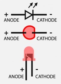
The Anode pin is (+) pin. The Cathode pin is the (-) pin.
If you connect the positive terminal of a supply to the Anode and the negative supply terminal to the cathode of the LED, the LED will glow.
In SMD (surface Mount Devices) the anode and cathode indications are difficult to notice.
You must refer to the datasheet to understand the polarity.
Warning: Never connect an LED directly to the supply. It would help if you always put a resistor in series. We will see how to calculate the resistor value later in the later section.
How to identify the positive terminal of an LED?
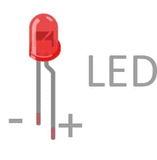
The LED’s positive terminal will be longer than the negative terminal, as shown in the image above.
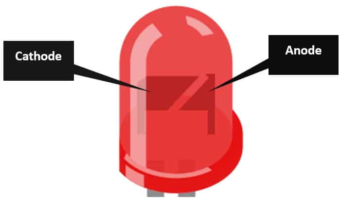
What if the LED pins are cut already to match the length?
You will find two parts if you can still see through the LED glass. One part is significantly larger than the other.
In the image below, you can easily see the cathode part being wider than the anode inside the LED.
Let us understand a few critical LED specifications from an example datasheet.
| Parameter | Value | Remarks |
| Forward voltage | 2.1 to 2.8 V | Always consider maximum LED forward voltage while choosing a supply. |
| Reverse Current | 100 uA | |
| Reverse Voltage | 5 V | Voltage beyond this value will destroy the LED permanently. |
| Peak Wavelength | 590 nm | Different wavelengths correspond to different colours. |
| Luminous Intensity | 5 to 15 mcd |
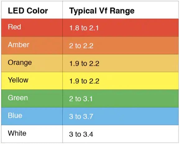
- Forward Voltage – The minimum voltage needed to turn on the LED. The red LEDs’ forward voltage is usually lower than other color LEDs. The forward voltage of the white LEDs is generally in the range of 3 V to 3.5 V.
The Arduino UNO drives all LEDs because a 5 V supply powers it. If you are using Arduino micro or other boards powered by 3.3 V, you have to use additional circuitry.
- Maximum Forward Current – The maximum current the LED can handle. If you increase the current, the LED will get hot and burn out. It is also dangerous to void the current limit.
- Reverse Voltage – Reverse voltage is the maximum reverse voltage that can be safely applied to an LED. If you apply reverse voltage to the LED, the LED will turn on. There is a limit on the value. If you apply a voltage higher than the specified reverse voltage, the LED will fail or burn.
- Luminous Intensity – Luminous Intensity is a measure of the brightness of the LED. If you have two LEDs with different luminous intensities at the same forward current, the LED with the higher luminous intensity is more efficient.
- Peak Wavelength – The colors will vary depending on the wavelength of the light emitted by the LEDs. So, the wavelength is a more precise way of labeling the LED color.
In the image below, you can see that visible light has a wavelength range from 400 nm to 700 nm.
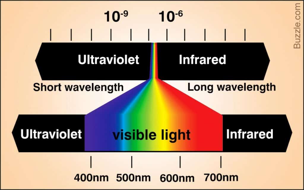
The example datasheet 590 nm was the wavelength with the color yellow diffused, which can relate to the image above.
LED forward voltages for various colour LEDs are summarized in the table below.
Why should you always use a resistor in series with the LED?
The LEDs are current controlled devices. Once you provide the forward voltage for the LED, they act like a closed switch.
Hence there should be another element to limit the current.
You can use the equation below to find the resistor’s correct value.

Where,
R → Resistance of the resistor
VS → Input supply voltage
VLED → Forward voltage of the LEDILED → Forward current of the LED
Step-By-Step Instructions To Connect The LED To An Arduino UNO
In this section, we will build a project using Arduino UNO and the LED. The connections are easy to take significantly less time to complete.
Let’s get started with the hardware connections!
You will find the necessary Arduino code in the later sections.
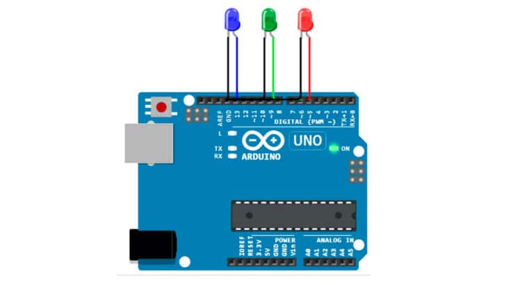
How To Connect An LED to the Arduino UNO?
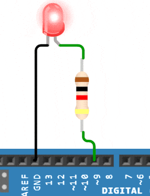
Below is the step-by-step connection guide to complete the Arduino and the LED together.
To complete the connections, you will need:
- Arduino UNO
- LED
- Resistor
Step 1: Start with the GND connections.
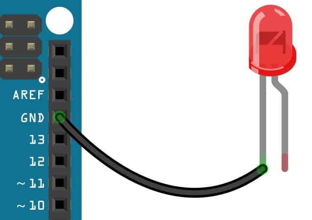
Connect the cathode pin of the LED to the Arduino’s GND pin. You can choose any of the GND pins available.
Step 2: Connect the current limiting resistor.
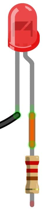
Connect a 220-ohm resistor to the anode pin of the LED. You can choose any resistor value between 220 ohms and 1 kOhm.
Step 3: Complete the resistor connection.
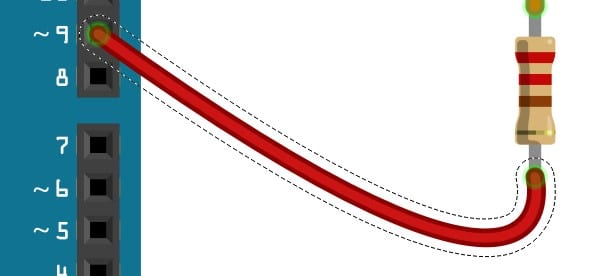
Connect the other end of the resistor to Pin 9 of the Arduino UNO.
Arduino Code Example For The Arduino And The LED Project
In this section, we will see a few examples of how we can drive the LED using Arduino UNO.
You can copy and paste the code in the editor window and program the Arduino.
Project 1 – Blink the LED using digitalWrite()
In this Project, you will toggle the LED every second.
int ledPin = 9;

void setup() {
  pinMode(ledPin, OUTPUT);
}

void loop() {
  digitalWrite(ledPin, HIGH);
  delay(1000); // Wait for 1 second

  digitalWrite(ledPin, LOW);
  delay(1000); // Wait for 1 second
}
This is a classic way of toggling a GPIO pin. Specify the Arduino Pin to which the LED is connected.
int ledPin = 9;
Set the pin as output using the instruction below.
pinMode(ledPin, OUTPUT);
Set the pin status to HIGH or Low using the digitalWrite function.
digitalWrite(ledPin, HIGH);
Here is the output. The LED turns off and turns on every second.
Project 2 – Blink the LED using millis()
Here is another method to toggle the LED. Instead of using the delay() function, you can use the millis() function to track the time.
Once 1000 milliseconds have elapsed, you will change the pin status.
The program size is smaller than the previous program. If you have any questions related to the code, please post them in the comments.
int ledPin = 9;

void setup() {
  pinMode(ledPin, OUTPUT);
}

void loop() {
  digitalWrite(ledPin, (millis() / 1000) % 2);
}
The digitalWrite() function takes a number as a second argument. If you send a 1, the LED will turn ON (logic HIGH).
Since you are dividing the millis() by 1000, every time the millis() reaches a multiple of 1000, the modulus 2 will either generate a one or a zero.
Project 3 – Blink the LED using Timer Interrupts
Here is an advanced method to toggle the LED. Instead of using the functions, you will use built-in hardware timers to toggle the LED.
The advantage of using a built-in timer is that you can perform other software functions.
The delay() function occupied the program control entirely in the previous examples.
You are enabling the timer interrupt. In the Interrupt service routine, you will toggle the pin status.
The interrupt service routine is called every second.
int ledPin = 9;

void setup() {
  TCCR1A = 0;
  TCCR1B = 0;
  bitSet(TCCR1B, CS12);  // 256 prescaler
  bitSet(TIMSK1, TOIE1); // timer overflow interrupt
  pinMode(ledPin, OUTPUT);
}

ISR(TIMER1_OVF_vect) {
  digitalWrite(ledPin, !digitalRead(ledPin));
}

void loop() {
}
Project 4 – Blink the LED using Timers and Counters
int ledPin = 9;

void setup() {
  TCCR1A = 0;
  TCCR1B = 0;
  bitSet(TCCR1B, CS12);  // 256 prescaler
  OCR1A = 62500;
  bitSet(TCCR1A, COM1A0); // Toggle pin OC1A (9)
  pinMode(ledPin, OUTPUT);
}

void loop() {
}
In the code above, you are not using digitalWrite() function. You are using timers and counters together to toggle pin 9.
To learn more about the timer features of the Arduino, refer to the link.
FAQs About The LED And Arduino Projects
I have included a list of the most frequently asked questions about projects built using Arduino and LEDs.
If you have more questions, please post them in the comments section.
I will be glad to answer them.
1. How do I program to turn on LED lights using my Arduino?
The Arduino can directly drive the LEDs. You must send a logic high on the GPIO signal to turn on the LED.
You can use the digitalWrite() function to set the value of the GPIO to a high or a low.
There are two possible ways to connect the LED. Either you can source the current or sink the current.
You should decide the logic based on the way the LED is connected.
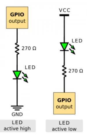
In the above image, the left LED will turn on when the GPIO pin is set to logic 1.
The right LED will turn on when the GPIO is set to logic zero.
2. Can I connect the LED directly to the Arduino?
The Arduino can support up to 20 mA of continuous current. If you are using only one LED, you can directly connect the LED to the Arduino.
If you are using multiple LEDs, it is better to use a buffer or a MOSFET switch to control them.
The Arduino can sink up to 20 mA per pin. When you connect multiple LEDs, the current consumption will be too high, damaging the GPIO port or the onboard regulator due to excess power.
3. Can I connect the LED without a resistor?
No. If you connect an LED without the resistor, the LED will sink the maximum current the Arduino UNO can supply.
The LED can burn out or blast, which is a very dangerous event.
Always connect a current limiting resistor in series with the LED.
4. How many LEDs can I light up with the Arduino UNO?
The number of LEDs you can light up depends on the set LED current.
If you use current-limiting resistors, which limit the current to 1 mA per LED, you can drive up to 20 LEDs without damaging the LEDs.
The LEDs will not be brighter. For Indoor use, 1 mA is sufficient in most cases.
Conclusion
In this article, we covered the basics of LEDs. and I showed you how four different ways of making an LED blink with Arduino.
I am confident that after reading this guide, you can now complete the connections and try all four methods of toggling the LEDs.
I have used LEDs in many different projects and often use them to indicate the program status. One single LED can indicate more than ten statuses!
You can vary the blink rate, change the number of blinks, etc.
What are you planning to use LED’s for?
Please share your projects in the comments below.

I am Puneeth. I love tinkering with open-source projects, Arduino, ESP32, Pi and more. I have worked with many different Arduino boards and currently I am exploring, Arduino powered LoRa, Power line communication and IoT.