In this tutorial you will learn how to use a Keypad and an Arduino to build a password protected system. This project can be a great way to enhance the security of your projects or create a simple access control system.
By the end of this tutorial, you will have a clear understanding of how to connect a keypad to an Arduino, write the necessary code, and implement a password lock system. We will also discuss some practical applications for this project.
So, let’s get started!
Required Parts
Below you will find the parts required for this project. Instead of the 4×4 Keypad, I used for this project you can also buy one of the common 4×3 Keypads – if you don’t need or want the alphabetic keys.

Arduino Uno

USB Cable for Arduino UNO

Dupont Wire Set
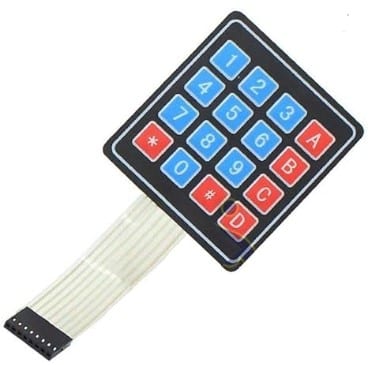
Keypad 4×4
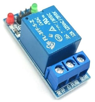
Relay Module
Makerguides.com is a participant in the Amazon Services LLC Associates Program, an affiliate advertising program designed to provide a means for sites to earn advertising fees by advertising and linking to products on Amazon.com. As an Amazon Associate we earn from qualifying purchases.
How does a Keypad work
A keypad is an input device that allows users to enter data or commands by pressing buttons. It consists of a grid of buttons, each representing a specific character or function. When a button is pressed, it closes an electrical circuit, which can be read by a microcontroller.
Matrix Keypad
Most keypads, including the popular 4×3 or 4×4 keypads, use a matrix arrangement. This means that the buttons are organized in rows (R1…R4) and columns (C1…C4), forming a grid. A 4×4 keypad has 4 rows and 4 columns and a 3×4 keypad has 4 rows and 3 columns.
Each button is connected to a unique combination of a row (R) and a column (C). See the internal circuit of a 4×4 keypad matrix below.
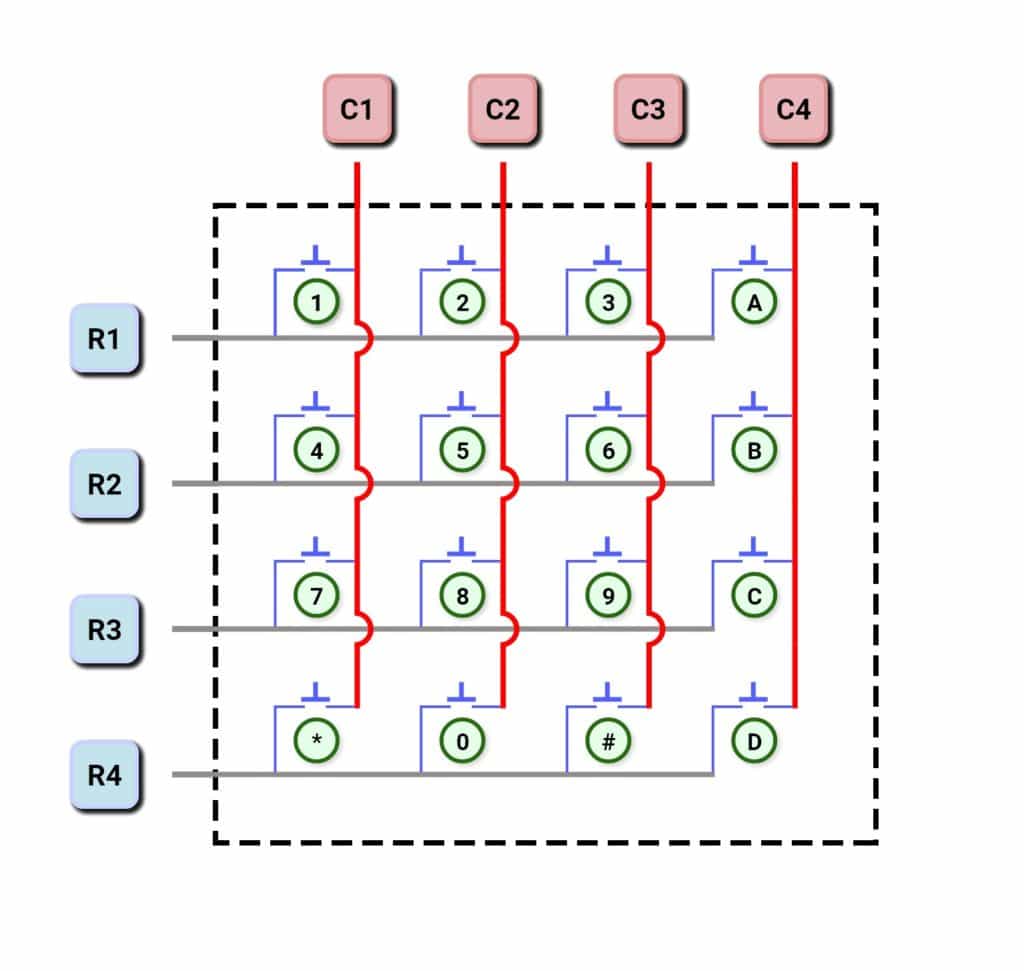
To detect which button is pressed, the microcontroller scans the rows and columns one by one. I will explain the scanning algorithm in detail in the next section.
Scanning Algorithm
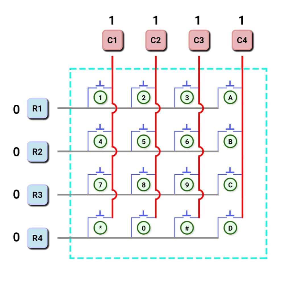
The scanning algorithm starts by setting the column pins to HIGH (logic 1), and all the row pins are to LOW (logic 0). The following image show the initial setup, when no key is pressed. The rows pins R1,…, R4 are at logic 0, and column pins C1,…, C4 are at logic 1.
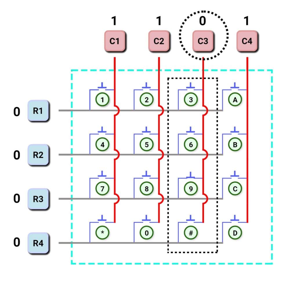
If a key is pressed, let’s say the number “9” key, then row R3 will make contact with column C3, and thus C3 will be connected to ground, and it will be at logic 0. Which means we have identified the column of the key that is pressed.
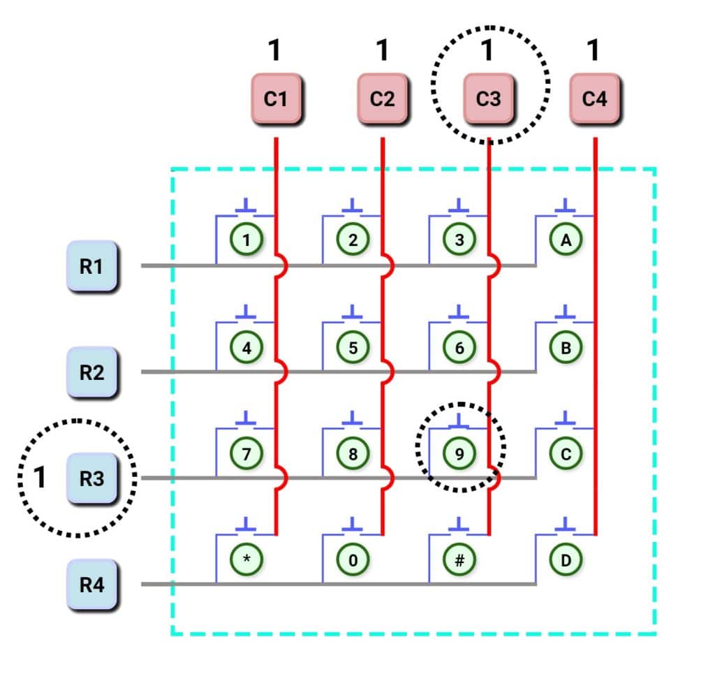
Now we have to find the row. This is achieved by setting each row individually to HIGH (logic 1) and monitoring the column (C3 in our case). When this column becomes HIGH (logic 1) again we have found the row of the key that is pressed:
As you can see, finding the pressed key in this matrix circuit is easy. Organizing keys in a matrix has the advantage that less IO pins are needed. We have 4×4 = 16 keys but require only 4+4 = 8 IO pins.
There remains one more problem to solve before we can use a simple keypad and that is debouncing.
Debouncing
When a button is pressed, it may make multiple contacts in quick succession, resulting in multiple signals being sent to the microcontroller. Debouncing can be handled in hardware or software but the cheap membrane switch keypads we are using here, do not have hardware debouncing.
It therefore must be implemented in code. We could do this ourselves but we will use the convenient Keypad library for this. It ensures that only a single press is registered, preventing false readings. This library also implements the scanning algorithm and identifying key presses becomes very easy with it.
However, in the next section I show you first how to connect the keypad to an Arduino.
Connect Keypad to Arduino
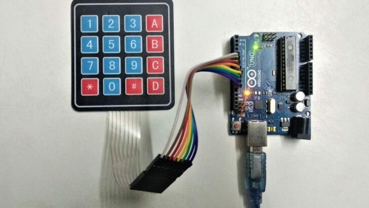
Connecting a 4×4 Keypad is very simple. Just connect the Arduino pins 11 to 4 in order to the connector of the keypad.
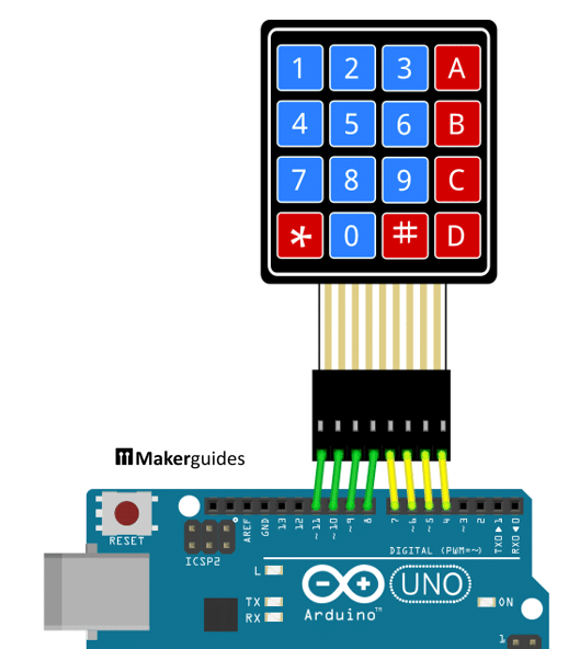
If you have a 4×3 Keypad, connect it in the same order, just don’t use pin 4. The following table show you which pins to connect for both keypad sizes:
| Arduino UNO | 4×3 Keypad | 4×4 Keypad |
| 11 | R1 | R1 |
| 10 | R2 | R2 |
| 9 | R3 | R3 |
| 8 | R4 | R4 |
| 7 | C1 | C1 |
| 6 | C2 | C2 |
| 5 | C3 | C3 |
| 4 | — | C4 |
In the following sections, I will show you three examples of how to use the keypad.
Example 1: Read Keypad keys
In our first example, we will start very simple and just read which key is pressed and print it to the Serial Monitor. Not very exciting but a very good test to verify the correct wiring of the keypad. You definitely should do this, before trying to implement something more complex.
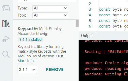
Install Keypad libary
However, first you need to install the Keypad library. Go to Sketch > Include Library > Manage Libraries and search for “Keypad”. Look for “Keypad by Mark Stanley” and install it:
Read Keypad keys
Once, the library is installed, copy the following code into the Arduino IDE and upload it to your Arduino board.
#include "Keypad.h"

const byte rowCount = 4;
const byte colCount = 4;
const byte rowPins[rowCount] = { 11, 10, 9, 8 };
const byte colPins[colCount] = { 7, 6, 5, 4 };
const char keys4x4[rowCount][colCount] = {
  { '1', '2', '3', 'A' },
  { '4', '5', '6', 'B' },
  { '7', '8', '9', 'C' },
  { '*', '0', '#', 'D' }
};

Keypad keypad = Keypad(makeKeymap(keys4x4), rowPins, colPins, rowCount, colCount);

void setup() {
  Serial.begin(9600);
}

void loop() {
  char key = keypad.getKey();
  if (key) {
    Serial.println(key);
  }
}
Let’s have a closer look at the code.
Constants and Variables
We start by defining the constants and variables required for the keypad. We have a 4×4 keypad with 4 rows and 4 columns. The row pins are connected to pins 11, 10, 9, and 8, while the column pins are connected to pins 7, 6, 5, and 4. We also define the characters that correspond to each key on the keypad in a 2D array called “keys4x4”.
If you have a 4×3 keypad or a keypad with different keys, this is the place to change it.
#include "Keypad.h"

const byte rowCount = 4;
const byte colCount = 4;
const byte rowPins[rowCount] = { 11, 10, 9, 8 };
const byte colPins[colCount] = { 7, 6, 5, 4 };
const char keys4x4[rowCount][colCount] = {
  { '1', '2', '3', 'A' },
  { '4', '5', '6', 'B' },
  { '7', '8', '9', 'C' },
  { '*', '0', '#', 'D' }
};

Keypad keypad = Keypad(makeKeymap(keys4x4), rowPins, colPins, rowCount, colCount);
Setup function
In the setup() function, we initialize the serial communication with a baud rate of 9600. This will allow us to communicate with the Arduino through the Serial monitor.
void setup() {
  Serial.begin(9600);
}
Loop function
In the loop() function, we continuously check for key presses on the keypad using the getKey() function from the Keypad library. If a key is pressed, we store it in the variable “key” and then print it to the Serial monitor using Serial.println().
void loop() {
  char key = keypad.getKey();
  if (key) {
    Serial.println(key);
  }
}
If you don’t see any output, check the baud rate for the Serial Monitor. Should you see wrong keys, check the wiring of the Keypad to the Arduino. If you use different pins or mix up the wires it will sort-of work but the keys are not mapped correctly.
Example 2: Check Password
In Example 1 we verified the correct connection of the keypad and implemented the fundamental code for reading keys. In Example 2, we will extend this code to build a password controlled access system. Have a look at the code first and I will describe it in detail below.
#include "Keypad.h"

const byte rowCount = 4;
const byte colCount = 4;
const byte rowPins[rowCount] = { 11, 10, 9, 8 };
const byte colPins[colCount] = { 7, 6, 5, 4 };
const char keys4x4[rowCount][colCount] = {
  { '1', '2', '3', 'A' },
  { '4', '5', '6', 'B' },
  { '7', '8', '9', 'C' },
  { '*', '0', '#', 'D' }
};
Keypad keypad = Keypad(makeKeymap(keys4x4), rowPins, colPins, rowCount, colCount);

const int maxPwdLen = 16;
const String password = "123#";
String input;


void setup() {
  Serial.begin(9600);
  input.reserve(maxPwdLen);
}

void loop() {
  char key = keypad.getKey();

  if (key) {
    input += key;
    if (input.length() >= maxPwdLen) input = "";
  }

  if (key == '#') {
    if (input == password) {
      Serial.println("SUCCESS");
    } else {
      Serial.println("FAIL");
    }
    input = "";
  }
}
Constants and Variables
The creation of the keypad object and the required constants are the same as before. In addition, however, we define the constant maxPwdLen that specifies the maximum length of the password. If you need a longer password, you have to adjust this constant.
We also define a string variable password that holds the correct password. Note that it ends with the “#” character. Later in the code, you will see that this signals the end of the entered password. So, while you can change the password to anything you like, it has to end with the “#” character or you have to change the code below.
The string variable input stores the user input and will be compared with the password defined above.
const int maxPwdLen = 16;
const String password = "123#";
String input;
Setup function
In the setup() function, we start the serial communication at a baud rate of 9600 and reserve memory for the input string. Using String in Arduino code is a bit risky, since you could run out of memory. We prevent this here by setting a maximum length of the password. Later in the code, we will ensure that the input does not get longer than that.
void setup() {
  Serial.begin(9600);
  input.reserve(maxPwdLen);
}
Loop function
The loop() function is where the main logic of the system resides. First, we use the getKey() function from the keypad library to get the currently pressed key as before.
void loop() {
  char key = keypad.getKey();
If a key is pressed, we add it to the input string. And if the length of the input string exceeds the maximum password length, we reset it to an empty string.
  if (key) {
    input += key;
    if (input.length() >= maxPwdLen) input = "";
  }
Next we test if the pressed key is the “#” key. In this case we check if the input string matches the correct password and print “SUCCESS” to the serial monitor. Otherwise, we print “FAIL”.
  if (key == '#') {
    if (input == password) {
      Serial.println("SUCCESS");
    } else {
      Serial.println("FAIL");
    }
    input = "";
  }
And that’s the basic implementation for a password access system. In the next section, we add a relay that we switch on when access is granted.
Example 3: Password controlled Relay
In a real world application we usual want to perform an action when the correct password is entered. For instance, releasing the lock of a door.
Wiring for Keypad and Relay
For this we will need to control a solenoid or a motor but they require too much current to be directly switched from an Arduino. Typically we will connect a relay instead, which in turn controls the actuator. The following image shows you how to add a relay to the project.
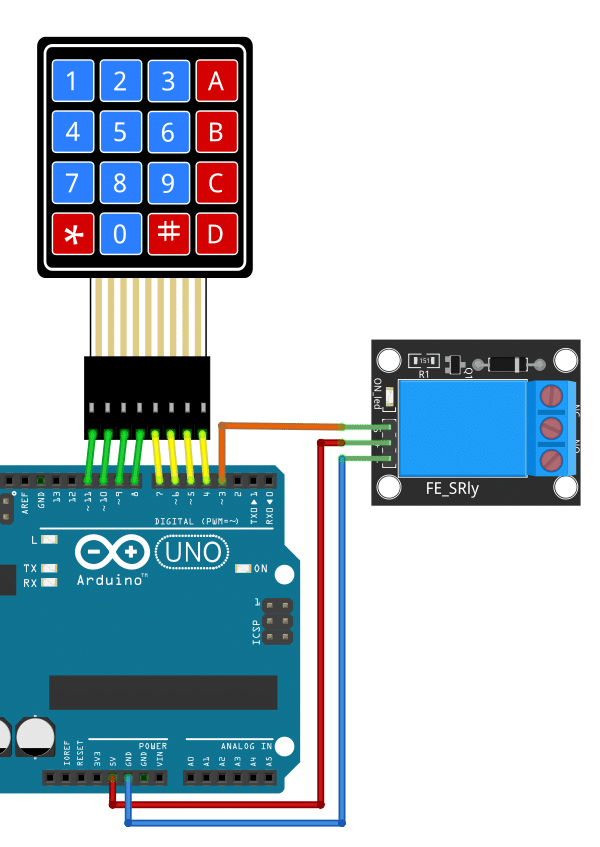
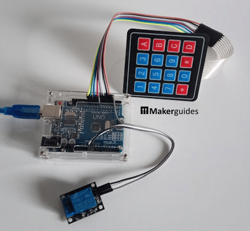
Simply connect the pin marked with Signal (S) of the Relay Module to pin 3 of the Arduino. For power connect the (+) and (-) pins of the Relay to 5V and GND of the Arduino, respectively. Note that we are using a Relay Module here. Below a picture of the complete project:
You could use a plain relay as well, but then you would have to add a flyback diode and a maybe a capacitor to make it a reliable circuit. The Relay Module takes care of that for us. For more information have a look at our tutorial How to use a Relay with an Arduino.
Code for Password controlled Relay
The code is almost identical to Example 2. The only difference is that we add a constant relayPin and enable the pin as output in the Setup() function. Furthermore, we temporarily switch on the relay for a second if the correct password was entered. This would release the door look for a second – enough time to open the door.
#include "Keypad.h"

// Create keymap and password constants as in Example 2
// Keypad keypad =
// const String password =
// ...


const int relayPin = 3;

void setup() {
  Serial.begin(9600);
  input.reserve(maxPwdLen);
  pinMode(relayPin, OUTPUT);
}

void loop() {
  char key = keypad.getKey();

  if (key) {
    input += key;
    if (input.length() >= maxPwdLen) input = "";
  }

  if (key == '#') {
    if (input == password) {
      Serial.println("ACCESS GRANTED");
      digitalWrite(relayPin, HIGH);
      delay(1000);
      digitalWrite(relayPin, LOW);
    }
    input = "";
  }
}
And there you have it. A password controlled access system using a 4×4 Keypad, a Relay Module and an Arduino.
Possible extensions could be the addition of an LED to signal locking status, or failed attempts. Also a buzzer for audible feedback would be nice. Finally, we could make the system programmable, allowing the user to create new or multiple passwords.
Conclusion
In conclusion, building a password-protected system using an Arduino and keypad is a great way to add an extra layer of security to your projects. By following the steps outlined in this guide, you have learned how to connect a keypad and relay to an Arduino, as well as how to write the necessary code for a password lock system.
Using a keypad allows for a user-friendly input method, and the Arduino’s ability to control a relay provides the means to activate or deactivate a connected device or system. This combination opens up a wide range of practical applications, such as controlling access to a door, activating a motorized gate, or even securing valuable items in a safe.
Remember to choose the appropriate keypad for your project, considering factors like the number of buttons and the layout (4×3 or 4×4). Additionally, ensure that you select a relay that can handle the voltage and current requirements of your specific application.
As with any project, it is important to test and troubleshoot your setup thoroughly before deploying it in a real-world scenario. This will help identify any potential issues and ensure the reliability and functionality of your password-protected system.
We hope this guide has provided you with the knowledge and confidence to embark on your own password-protected projects using an Arduino and keypad. Experiment with different code variations and explore additional features to customize your system according to your specific needs.
If you have any further questions or need assistance, feel free to refer to the Frequently Asked Questions section.
Happy making and stay secure!
Frequently Asked Questions
Here are some frequently asked questions about using a keypad with an Arduino.
Q: What is a keypad?
A: A keypad is an input device that consists of a set of buttons arranged in a grid. Each button represents a specific character or function and can be pressed to send a signal to a microcontroller or other electronic device.
Q: Can I use a different keypad with Arduino?
A: Yes, you can use different types of keypads with Arduino. The most common keypads used are 4×3 and 4×4 keypads. The setup and code may vary slightly depending on the keypad you choose, but the basic principles remain the same.
Q: How does a keypad work?
A: Keypads typically use a matrix arrangement, where each button is connected to a specific row and column. When a button is pressed, it completes a circuit between the corresponding row and column, allowing the microcontroller to detect which button was pressed.
Q: What is the difference between a 4×3 and a 4×4 keypad?
A: The main difference between a 4×3 and a 4×4 keypad is the number of buttons they have. A 4×3 keypad has 12 buttons arranged in a 3×4 grid, while a 4×4 keypad has 16 buttons arranged in a 4×4 grid.
Q: How do I connect a keypad to Arduino?
A: To connect a keypad to Arduino, you will need to identify the row and column pins of the keypad and connect them to the appropriate digital pins on the Arduino. In the code you have to provide a mapping from pins to keys.
Q: What is the code for a password lock system using a keypad and Arduino?
The code for a password lock system using a keypad and Arduino involves reading the keypad input, comparing it with a predefined password, and controlling the relay based on the input. The code typically includes functions for initializing the keypad, reading input, comparing passwords, and controlling the relay.
Q: What are some practical applications of a password-protected system with a keypad and Arduino?
A: A password-protected system with a keypad and Arduino can be used in various applications, such as home security systems, access control systems, and electronic lock systems. It provides a secure way to control access to certain areas or devices.
If you have any more questions or need further assistance, feel free to reach out to us.

Hiren is a professional Embedded Engineer with a Master’s Degree
in Electronics and Communication Engineering. He is proficient in C and
C++ and enjoys building DIY projects on Arduino, ESP32, PIC32, STM32 & Raspberry PI boards.