In this tutorial, I will show you how to use a relay with Arduino and how relays work. By the end of this tutorial, you will have all the knowledge to interface relays with Arduino. This will be able to control motors, power switches and other high power applications.
The first part of the article covers the basics of relay and relay board connections. I will then continue with the Arduino project where you will drive a relay using Arduino to control a DC circuit.
At the end of the article, you will find all the details to control an AC circuit ( 230 V lamp, dimmer etc) using Arduino.
Let’s get started!
1: Components Needed To Control Relay Using Arduino
Hardware Components
- Arduino Uno Rev3 x 1
- Relay Module x 1
- Dupont wire x 3
- Arduino USB cable (for powering and programming) x 1
- Batteries (or DC power supply)
- Battery connector
Tools
- Screwdriver (to connect wires to the relay module) x 1
- DC motor (load) x 1
Software
Makerguides.com is a participant in the Amazon Services LLC Associates Program, an affiliate advertising program designed to provide a means for sites to earn advertising fees by advertising and linking to products on Amazon.com. As an Amazon Associate we earn from qualifying purchases.
You will be able to complete the project with the items listed above. I suggest you first go through the entire article to understand the connections, safety tips and some more useful hints.
You will program the Arduino to control the relay board. The relay board will then turn the load ON or OFF.
Relay Basics
Relays are helpful when you need to control a circuit using a low power signal (Arduino Digital Pin, for example).
There are different types of relays for multiple applications. The mechanical relay will consist of a coil which when activated, closes or opens the switch (due to magnetic properties of the coil).
The Solid-state Relays(SSR) are less bulky and consist of no moving parts.
Here is one example of a 5 V relay.
Example data sheet – OMIH-SH-112L,394
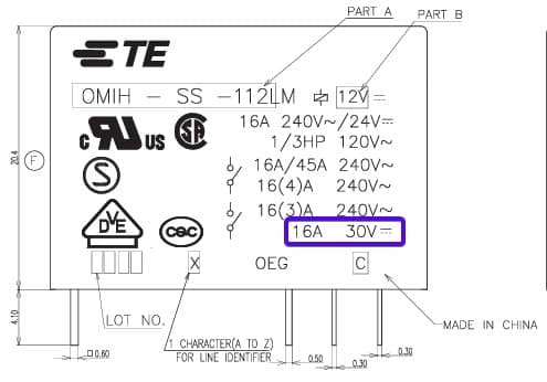
I have taken the image from the above datasheet. If you are planning for a DC load, the maximum current the relay can support is 16 A.
Depending on the type of the load, you have to also derate it (choose a much higher current rated relay than load current)
Important Parameters
I will brief you on the most important parameters you should look at, before buying the relay for your application.
- Switching Voltage – Each relay will have a rating separately for AC and DC. You have to make sure that the load you need to drive requires a voltage less than the relay switching voltage.
Example: If I want to drive a 9 V DC motor using the relay, I will go with a relay that has the switching voltage rated to 12 V or higher
- Contact current rating – This rating should be higher than the maximum expected load current.
- Coil voltage – This is the voltage needed for the relay to turn on. You cannot provide voltage more than 5 V using Arduino. Hence you can use a circuit similar to below to provide the 12 V needed by the relay.
Function
The transistor acts like a switch. You can use an Arduino digital pin to control the transistor. You will need this circuit if you want to drive the relay and not a relay board.
At the end of the article, you will see the benefits of using relays and relay modules.
When you send a Logic 1 on the digital output pin of the Arduino, the transistor will be ON. When the transistor is ON, the relay will get the required coil voltage (VCC) and it will be ON.
To turn OFF the relay, you have to send a Logic 0 to the transistor. Once the transistor is off, the relay coil voltage drops to zero. The load will be now disconnected.
You have to use a diode in parallel with the relay coil. This is for protecting both the transistor and Arduino as well.
When the relay is ON, The coil in the relay will have energy stored in the form of a magnetic field. Once the relay is turned OFF, the magnetic field energy will be dissipated in the form of high voltage. The Flywheel diode will act as a clamp and also provide the path for the coil to discharge the energy stored safely.
For different types of relay drive circuits, I recommend you to go through the relay switch circuit tutorials.
2: Step By Step Instructions
I will highlight the important pin details and the connections first. The following steps will take you through a step by step connection guide to complete this project.
Pinout information
| Arduino UNO | Relay Board |
| 5 V | (+) Positive Power Supply |
| GND | (-) Negative Power Supply |
| PIN 7 | S pin (input pin) |
You will find the pin description on the load side of the relay module in the table below.
| Relay Board Pin | Description |
| NO | Normally Open – This pin will be connected to the COM pin when the relay is ON. |
| COM | Common |
| NC | Normally Closed – This pin is connected to the COM pin when the relay is OFF. |
Step 1: Wiring Arduino and the relay board
In this step, I will show you the wiring needed between Arduino and the relay.
1) Take a jumper (Dupont cable) and connect one end to PIN 7 of Arduino
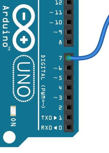
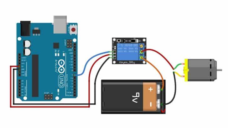
2) Connect the other end of the jumper to the S PIN on the relay module. The connection will look like the image below
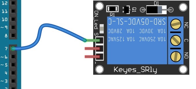
3) Make a connection between Arduino 5 V pin and the (+) PIN on the relay module
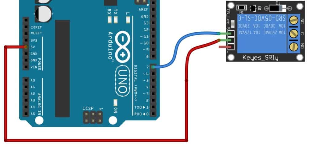
4) Make a connection between the Arduino GND pin and the (-) PIN on the relay module
You will find three GND pins on the Arduino UNO. You can connect to the GND PIN which is more easily accessible.
Now, You have completed the connections between Arduino UNO and the Relay module.
In the next steps, we will connect the relay module to the load.
Step 2: Wiring the Relay board to the Supply and the load
In this step, I will show you how to connect a 9 V supply and the load to the relay module. I have taken the DC motor as an example for the demo.
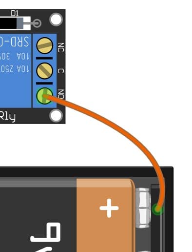
1) Connect the positive terminal of the 9 V battery to the NO PIN of the relay module
The switching part of the relay is electrically isolated from the driver side (where you have made a connection from Arduino).
This isolation helps to protect Arduino from high voltage supply and loads connected to the relay.
2) Connect the C (common) PIN of the Relay module to the Positive terminal of the DC motor
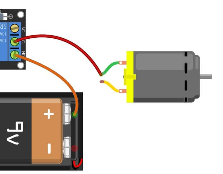
You will be able to identify the positive and negative terminal on the DC motor by the color of the wires.
The Red wire is the positive terminal and the black wire is the negative terminal of the DC motor.
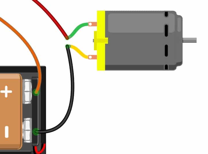
3) Connect the negative terminal of the battery to the DC motor
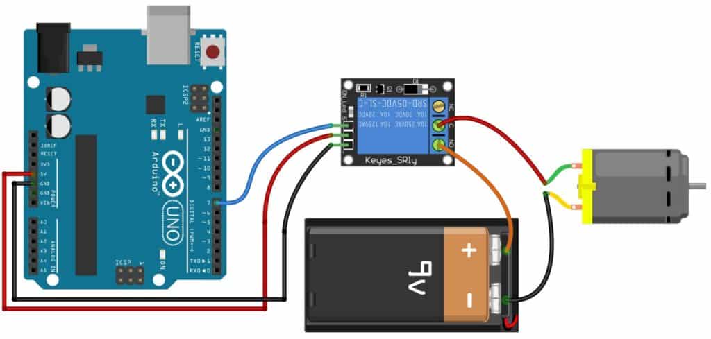
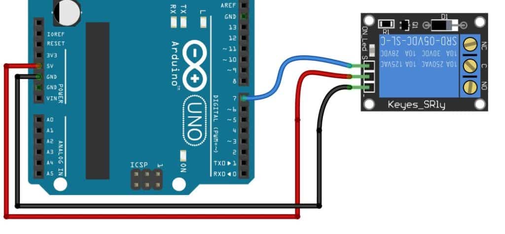
Step 3: Complete wiring diagram for How to use a Relay with Arduino

You can use the connection diagram to verify your connections once more! If nothing happens make sure that you told the Arduino to toggle the PIN 7 so that the relay switches between ON and OFF states.
You will find the code for the Arduino in the next step!
The same steps apply to both a 12 V supply and a 9 V supply! Always make sure that the relay rating is higher than the supply voltage.
When you are working with AC mains, you have to take special care. Always make connections with AC mains disconnected. High voltage is very dangerous and safety always comes first!
You should always insulate the open ends of the cable and provide a cover to protect others from accidentally touching the relay section.
Step 4: Arduino Sketch for How to use a Relay with Arduino
The sketch toggles the relay ON and OFF every one second. This is a simple sketch only for the demo.
In real applications, you can drive the relay to turn on light when you detect a motion or turn on the motor when the water level is below a certain threshold!
The relays find their applications all around you!
- Open Arduino IDE
- Copy and paste the below code in the Arduino Editor tab
- Connect Arduino to the PC using the USB cable
- Program the Arduino
#define RELAY_PIN 7

void setup() {
  // initialize digital pin RELAY_PIN as an output.
  pinMode(RELAY_PIN, OUTPUT);
}

// the loop function runs over and over again forever
void loop() {
  digitalWrite(RELAY_PIN, HIGH);   // turn the RELAY on
  delay(1000);                     // wait for a second
  digitalWrite(RELAY_PIN, LOW);    // turn the RELAY off
  delay(1000);                     // wait for a second
}
3: Relay Versus Relay Board? Which One Should You Choose?
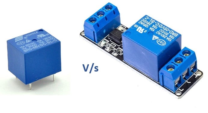
Relay modules come with additional circuitry and components on a board mounted. I would go with the Relay module for quick prototypes for the following reasons.
- Comes with easy to use connectors
- Contains all the necessary drive circuitry
- Some modules will have an LED indication to tell the relay status
- Easy to mount on a fixture (mounting holes will be there)
- Saves time for prototype
I will also tell you why I would go for a single relay.
- Saves a lot of space
- Not all relays you need comes in a module
- I can design my own drive circuitry and be sure about it
Hence, both connecting Arduino to Relay as well as Relay boards bring you unique advantages!
Conclusion
In this article, I covered the basics of a relay and important parameters of a relay to look for.
I also showed how to complete the connection between Arduino and relay module with a DC motor load as an example.
It would be great to hear from you. Did you find this article useful? Do you have some suggestions?
Please reply in the comments and I will be glad to reply to all your comments.
Benne is professional Systems Engineer with a deep expertise in Arduino and a passion for DIY projects.
Kristo Poljakov
Monday 5th of February 2024
"Relay Board Pin Description NO Normally Open – This pin gets connected to the COM pin when the relay is OFF. When the relay is ON, this pin gets connected to the COM pin. COM Common NC Normally Closed – This pin gets connected to the COM pin when the relay is OFF. When the relay is ON, this gets disconnected from the COM pin"
Surely this is wrong. NO and NC can't both connect to the COM when the relay is OFF at least when you use relay the way it is meant to be. :D
Stefan Maetschke
Tuesday 6th of February 2024
Good catch! Thanks. Much appreciated! The error has been fixed. Obviously it is: NO Normally Open – This pin is connected to the COM pin when the relay is ON. NC Normally Closed – This pin is connected to the COM pin when the relay is OFF.
Ivor
Thursday 8th of June 2023
Benne - you're heaven sent right now! I'm trying to do something similar and would love your input PLEASE?! I have a relay controlled by a transceiver. What i'd like to do is detect the state of the relay based on the remote button pressed (1 of 2) - if 1/"open" then move a servo x degrees and if 2/"close" move servo back to original place. Happy to share more details via email, but PLEASE HELP.
David Emery
Wednesday 8th of February 2023
How many relays can I control from a single pin? I have a project where I need to control two relays as a set (basically to create a 4PDT relay.) Can I control both relay boards from a single output pin>
Stefan Maetschke
Saturday 2nd of December 2023
It will depend on the relays. An Arduino Uno can safely drive 20mA of current on a single pin (continuously). If the two relays together draw more than that, you risk damaging your board. But why not just use another, second pin?
Alternatively you could use three relays. One relay that switches the two other relays. Or a transistor/Mosfet to do the same. BTW: Many relays can switch two independent circuits at the same time. In this case you use one relay one one pin and that relay controls the second relay and switches one of the circuits, while the second relay switches the second circuit.
If you are short on output pins you can use an IO multiplexer to "add" more pins and then control the two relays using two pins.
Petxentxo
Friday 1st of December 2023
@David Emery, I have the same question, but after such a long Time waiting for the kindness of a reply, am afraid nothing Will ever happen. Sad as it Is, that s what it Is.
Kevin
Wednesday 19th of October 2022
Your circuit with the transistor is interesting in as much as it looks to me that the flywheel diode does nothing. When the transistor turns off, ground potential to the relay and the anode of the flywheel diode is removed, so the diode has no path to ground and makes it useless to the circuit. What are you thoughts?
Damon
Sunday 18th of September 2022
Great clear article and the right length! One question: You wrote, "Depending on the type of the load, you have to also derate it." It sounds like the derate is different for different applications? What types of loads require how much? Could you add a [appendix?] table or link to a resource on this?