TFT displays have been around for decades. These low-cost and easy-to-use LCDs are essential to the human-machine interface design.
The availability of lightweight libraries makes it easy to build your own Arduino projects with TFT displays.
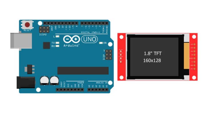
I will take you through a generic 1.8-inch TFT display module in this article.
You will learn how to connect the TFT controller to an Arduino UNO, pinouts of the TFT display board, and the Arduino code example.
You can use TFT displays in HMI products such as room temperature controllers and attendance systems, weather monitoring devices, infotainment systems, and even video game consoles.
By the end of this article, you can create your text and change the colors based on your preference.
You can then start building projects based on your requirements.
Let’s begin!
Components Needed To Build Arduino And TFT display Project
Hardware Components
- Arduino Uno Rev3 x 1
- 1.8 inch TFT color Display x 1
- Dupont wire x 1 set
- Arduino USB cable (for powering Arduino and programming) x 1
- Breadboard x 1 (optional)
- BergStick Connectors (optional)
Software
Makerguides.com is a participant in the Amazon Services LLC Associates Program, an affiliate advertising program designed to provide a means for sites to earn advertising fees by advertising and linking to products on Amazon.com.
What Is A TFT Display Module?
This article is part of our series on the different types of displays that you can use with Arduino, so if you’re weighing up the options, then do check out our guide to the best displays to use with Arduino.
TFT LCD stands for Thin Film Transistor Liquid Crystal Display. The display can be on screens, tablets, mobile phones, kiosks, and more.
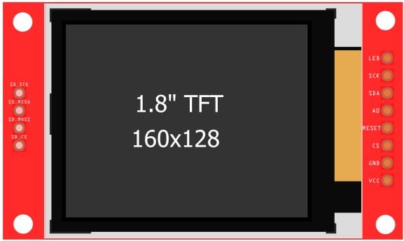
Let us see a view of a TFT LCD module. In the following section, we will see the pin definition and the pin mapping table for the connection between Arduino and the TFT display.
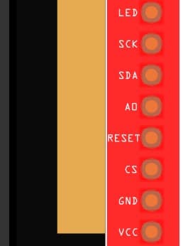
| Pin Name | Pin Type | Description |
| LED | Supply | Connect 3.3 V to this pin. |
| SCK | SPI Clock Pin | SPI clock pin. Depending on the type of the Arduino board, you have to set the pin connections accordingly. |
| SDA | SPI Data Pin | SPI Data pin. Depending on the type of the Arduino board, you have to set the pin connections accordingly. |
| A0 / DC | Data Command Select Pin / Analog Pin | Most of the time, you have to find the relevant termination needed from the LCD datasheet. Terminate this pin to Logic high using a 10 ㏀ |
| RESET | Reset Pin | Resets the LCD controller |
| CS | Chip Select | SPI Chip select line |
| GND | Ground Connections | Ground connections. Always use a short cable for GND connections. |
| VCC | 3.3 V – 5 V | Supply pin for the LCD |
You can find an example of a TFT Display controller datasheet here. Please visit the link for more information on the SPI interface on Arduino.
The ST7735 is an LCD controller IC used in many TFT display modules.
The Arduino UNO’s SPI lines communicate with the ST7735 IC.
Here are the basic protocol details from the ST7735 datasheet.
The waveform below presents the status of the SPI lines ( Chip select, I2C Data line, I2C Clock line) timing characteristics.
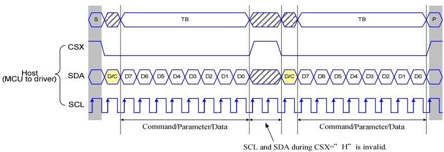
The data frame is written over SPI protocol in the following manner.
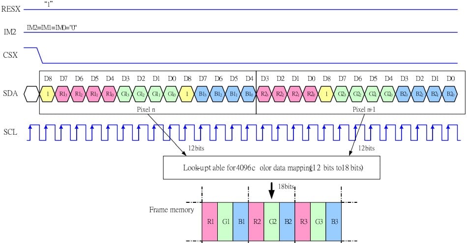
The RGB are the primary colors. The RGB format 4-4-4 means the Red, Green, and Blue colors are represented by 4-bit wide information.
Since it is 4-bit wide, the maximum levels for each color possible are 16. You can create 4096 colors.
There are options for you to increase the color depth. The RGB 5-6-5 is yet another format, which can produce up to (32 x 64 x 32) = 65536 colors.
You can see the tradeoff here. Going for a better color resolution provides vibrant display options, but memory usage will increase with the color resolution.
For example, an image of a width 240 x 320 will consume different amounts of memories based on the formats chosen.
- 240 X 320 = 76800 pixels
- Each pixel needs 12 bits to represent the color in RGB 4-4-4 format
- 12 * 76800 = 921,600 bits for the entire image
- In the case of RGB 5-6-5 format, each pixel’s color information will consume 16 bits
- 16 * 76800 = 1,228,000 bits
The overall memory needed increases by 33 % if you switch from RBG 4-4-4 format to RGB 5-6-5. This increase the demand for the MCU RAM, code size, and time delay to transfer higher data.
Hence, planning the memory requirements and color quality upfront is wise.
I hope this has given some insights into the rationale behind making decisions on the color format.
Note: The calculations shown above are a rough estimate. Depending on the format, you must pad some dummy bits, adding to the consumed memory bits.
Step-By-Step Instructions To Connect A TFT display To An Arduino
The following section gives step-by-step details to connect the TFT display to your Arduino Board.
You may come across several versions of the TFT display from several sources.
Most of the 1.8-inch TFT displays, are SPI controlled, and you will find that even the pin mappings match.
How To Connect The TFT Display To The Arduino UNO?
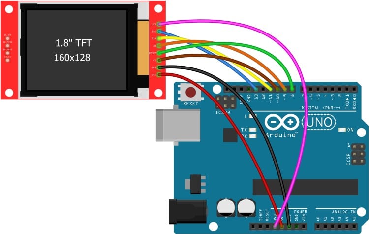
Here are the details required to complete the Arduino and the 1.8-inch TFT display.
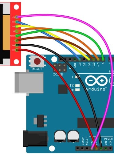
The final connection looks like the below image.
Step 1: Let us begin with the TFT display
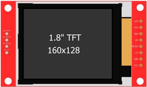
There are pins on either side of the board. On the right-hand side, you have pins related to the display and the power.
On the left-hand side, you get pins related to the SD card interface.
Step 2: Connect the SPI clock pin to the Arduino
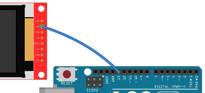
Connect pin 13 of the Arduino to the SCK pin of the display module.
Step 3: SDA pin connection
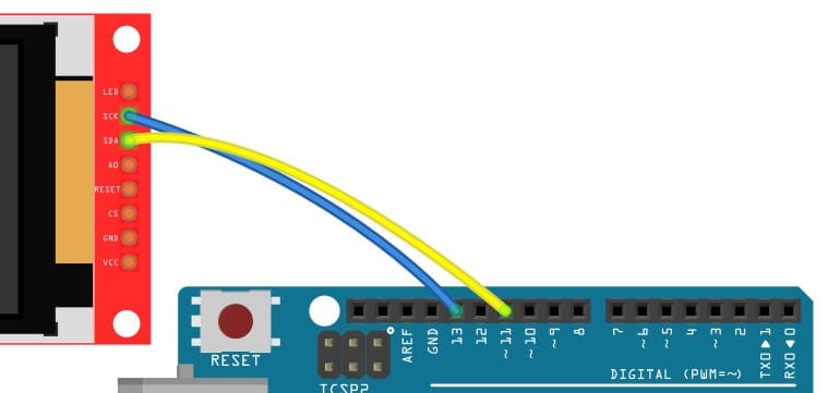
Connect pin 11 of the Arduino UNO to the SDA Pin of the display
Step 4: A0 connection
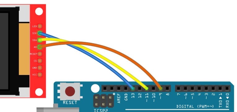
Connect pin 9 on the Arduino UNO to the A0 pin on the LCD module.
Step 5: RESET Pin connection
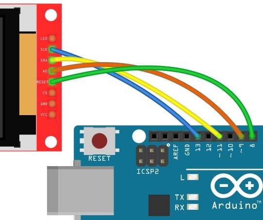
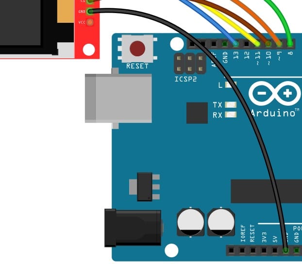
Connect the pin 8 on the Arduino UNO to the Reset pin on the LCD module.
Step 6: CS line connection
The Chip select must be connected to pin 10 of the Arduino UNO, as shown in the figure
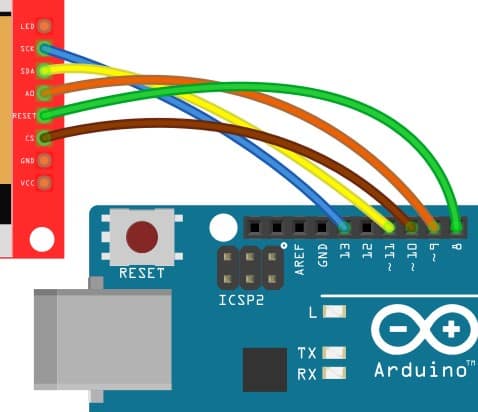
Step 7: Ground connection
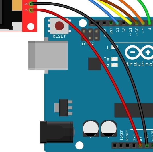
Connect the LCD board’s ground pin to the Arduino’s GND pin. You can choose any of the GND pins available on the Arduino UNO.
Step 8: Power supply connection
The 5 V supply from Arduino supplies the LCD via this pin.
Step 9: Connect the LED pin of the display to the 3.3 V pin on the Arduino
Step 10: Complete Arduino and TFT Display connection overview

The LCD module accepts 5 V as input. Connect the 5 V pin on the Arduino to the 5 V pin on the LCD.
This completes the essential connections needed to drive a TFT display from an Arduino UNO.
Congratulations!
1.8-Inch TFT Display Arduino Code Examples
In this section, I will take you through a simple Arduino program that is very easy to understand and modify on your own.
The source of the code is retained in the comments section of the code.
The Arduino code below displays the text “Hello, World!” on the screen. The font color will be changed every 200 ms.
The Complete Arduino Code
Open the Arduino IDE and click on the “File” option. Under the file options, select “New.”
#include "TFT.h"
#include "SPI.h"

#define cs   10
#define dc   9
#define rst  8

TFT TFTscreen = TFT(cs, dc, rst);

void setup() {
  TFTscreen.begin();
  TFTscreen.background(0, 0, 0);
  TFTscreen.setTextSize(2);
}

void loop() {
  int redRandom = random(0, 255);
  int greenRandom = random (0, 255);
  int blueRandom = random (0, 255);

  TFTscreen.stroke(redRandom, greenRandom, blueRandom);

  TFTscreen.text("Hello, World!", 6, 57);

  delay(200);
}
TFT Display And Arduino Code Walkthrough
The summary of the Arduino code is available below.
The below two lines adds the required libraries for the display module.
TFT and SPI headers contain the required functions to interact with the display over the SPI line.
#include "TFT.h"
#include "SPI.h"
Here, you are mapping the Arduino UNO pins to the chip select pin, data command pin, and the reset pin.
#define cs   10
#define dc   9
#define rst  8
If you are using an Arduino Mega or any other Arduino board, you should update the pin numbers accordingly.
TFT TFTscreen = TFT(cs, dc, rst);
We are creating the object by name TFTScreen of type TFT.
Here we will send the pin numbers to which the chip select, data/command, and the RESET pins are connected.
  int redRandom = random(0, 255);
  int greenRandom = random (0, 255);
  int blueRandom = random (0, 255);
In the above lines you are creating random numbers between 0 and 255.
Later, you will assign it to the redRandom pixel.
Along the same lines, you also generate two random numbers and assign them to the greenRandom and the blueRandom variables.
TFTscreen.stroke(redRandom, greenRandom, blueRandom);
The function stroke under the class TFTscreen sets the color to the values sent as arguments.
In this function, you send the values once every 200 ms using the delay() function below.
delay(200);
The function below displays the entered text in double-quotes.
TFTscreen.text("Hello, World!", 6, 57);
Note: Here is a link to an online Arduino Simulator which can simulate Arduino UNO, LCDs, and more. You can find a few examples here.
FAQs About The Arduino 1.8-inch TFT Color Display
In this section, you will get answers to the most frequent questions on the Arduino and the 1.8-inch TFT display projects.
If your question is still not answered, please post the question in the comment section.
I will be happy to answer.
1) How do I program the TFT LCD screen?
You can program the TFT LCD screen commonly available using SPI (Serial Peripheral Interface). There are several versions of the modules available.
Most of them come with an additional SD card holder as well. You can try out the project described in the article above.
2) Which is a better display, TFT or monochrome LCD?
There is a trade-off between the quality of the display, power consumption, and the simplicity of coding. The TFT displays consume more power and need more programming than a simple monochrome display.
TFT displays provide a faster refresh rate and provide smoother transitions. The quicker processing improves the look and feels of the so-called user experience for the user.
Higher power consumption is the disadvantage of the TFT displays as they are not a favorite choice for battery-powered devices.
3) Can Arduino drive a display?
Yes, Arduino can drive the smaller displays. There are several LCDs with built-in controllers which support SPI/I2C interfaces.
The Arduino can drive the boards. You can find one example in the article above.
The Arduino doesn’t need any special hardware to drive the controllers. The SPI or I2C interface can also be bit-banged, making it portable to any Arduino Board.
4) Is the TFT display better than AMOLED?
AMOLEDs are brighter and more power efficient than TFT displays. The viewing angles of AMOLEDs are better compared to the TFTs.
Conclusion
I hope it was fun learning the working of the TFT display and the required setup to bring up your own Arduino UNO + TFT display project.
If you have any suggestions to improve this article, I would be happy to hear about it.

I am Puneeth. I love tinkering with open-source projects, Arduino, ESP32, Pi and more. I have worked with many different Arduino boards and currently I am exploring, Arduino powered LoRa, Power line communication and IoT.