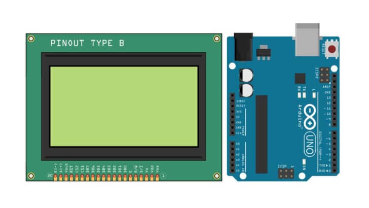
This tutorial will teach you how to use a graphical LCD with Arduino UNO. The 128×64 Graphical LCD is a versatile addition to your projects which needs a display.
You can find the applications of the graphical LCD in kiosks, metering applications, handheld billing devices, HVAC (Heating, Ventilation, and Air Conditioning) controllers, UPS, and more.
This article will take you through the basic pinout details (connector details) of the 128×64 graphical LCD board.
Further, you will see an example LCD controller which handles the LCD based on the commands from the Arduino UNO.
Once you understand the fundamental connection pin description, you will see the hardware connections necessary to complete an Arduino sketch to display an image on the LCD.
You will get complete working code at the end and answers to frequently asked questions about the 128×64 graphical LCD.
Let’s get started!
Components Needed To Build A Arduino And 128×64 Graphical LCD Project
Hardware Components
- Dupont wire x 1 set
- Arduino USB cable (for powering Arduino and programming) x 1
Software
Makerguides.com is a participant in the Amazon Services LLC Associates Program, an affiliate advertising program designed to provide a means for sites to earn advertising fees by advertising and linking to products on Amazon.com.
Basic Information About The 128×64 Graphics LCD
This article is part of our series on the different types of displays that you can use with Arduino, so if you’re weighing up the options, then do check out our guide to the best displays to use with Arduino.
A graphical LCD allows you to bring your graphics on the screen. The entire screen is divided into sets of closely placed pixels.
In the case of 128×64, the screen is made up of 128×64 = 8192 pixels.
Since this is a monochrome picture, 1 bit of memory is required to store the pixel’s value.
Each pixel can be either 1 or 0. Here is a link to a graphical LCD board from Vishay.
Here is the information from the datasheet
- Display Type: Graphic
- Display format: 128 x 64 dots (dots and pixels are used interchangeably)
- Built-in controller: Samsung KS 0107/KS 0108 (or equivalent)
- Duty cycle: 1/64
- + 5 V power supply
The above LCD board contains Samsung KS0107 or a similar driver. You can find the datasheet of the LCD controller IC – KS0107 IC here.
Solomon Systech SSD1322 LCD Controller is another example that can support 1128×64 graphical LCD.
The SSD1322 driver supports several modes of communication:
- MCU parallel 6800 series interface
- MCU parallel 8080 series interface
- Four-wire SPI
- Three-wire SPI
The critical difference between the 6800 and 8080 interfaces is the presence of dedicated RD and WR signals in 8080 versus combined RD/WR signals in the 6800 interfaces.
You may come across a different board with slightly different pin definitions. I encourage you to find the datasheet of the LCD controller IC on the module.
It is a good idea to buy the LCD controller that mentions the LCD controller on board.
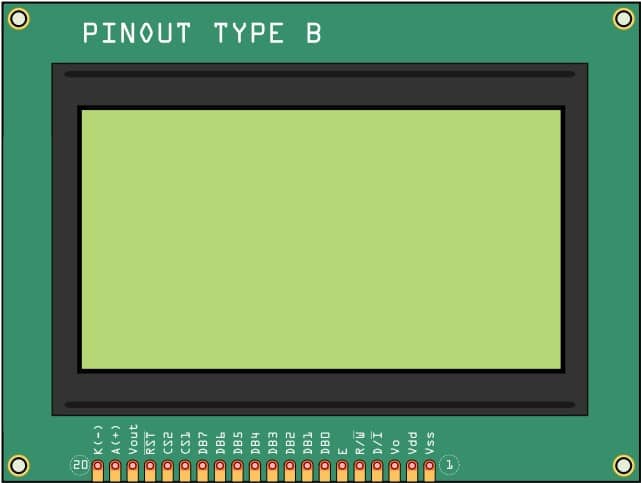
Let us understand the function of each pin in the 128×64 LCD module.

| Pin Number | Pin Label | Pin Function | Pin Description |
| 1 | VSS | Ground | Ground connection. Connect to the GND pin of the Arduino UNO. |
| 2 | VDD | Power supply | Supply the 5 V power supply here. For most of the LCD modules, you can connect the 5 V line from the Arduino pinout |
| 3 | V0 | Contrast Adjustment | The voltage at this pin defines the LCD contrast. |
| 4 | D/I# | Data/ Instruction | The pin defines whether the data lines contain data or the instruction. |
| 5 | R/W# | Data Read/ Write | This is a control line. A read operation is indicated by driving this pin high. A write operation is indicated by driving this pin low. |
| 6 | E | Enable signal | A high to low transition on this pin enables the LCD controller for communication |
| 7 | DB0 | Databus line | Data bit 1 |
| 8 | DB1 | Databus line | Data bit 2 |
| 9 | DB2 | Databus line | Data bit 2 |
| 10 | DB3 | Databus line | Data bit 3 |
| 11 | DB4 | Databus line | Data bit 4 |
| 12 | DB5 | Databus line | Data bit 5 |
| 13 | DB6 | Databus line | Data bit 6 |
| 14 | DB7 | Databus line | Data bit 7 |
| 15 | CS1 | Chip select line | Chip select CS1 |
| 16 | CS2 | Chip select line | Chip select CS2 |
| 17 | RST# | Reset line | You can reset the LCD controller by driving this pin Low. |
| 18 | VEE | Negative voltage output | VEE and V0 are used for contrast adjustments |
| 19 | A | Anode | This is the anode of the LED used for the backlight. |
| 20 | K | Cathode | This is the cathode of the LED used for the backlight. |
Step-By-Step Instructions To Connect A Graphic LCD To An Arduino
The following section gives step-by-step details to connect the Arduino UNO with the 128×64 Graphical LCD module.
How To Connect The 128×64 Graphical Display To The Arduino UNO?
The below section provides step by step summary to complete the connection between the Arduino UNO and the graphical LCD board.
Let’s get started! In this demo example, I am using the SPI interface supported by the LCD controller.
SPI interface uses less number of pins. There will be more free pins on the Arduino for other use cases.
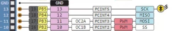
The GPIO13 Pin on the Arduino is the SPI clock pin. The “E” pin on the LCD board is the Clock pin. RS pin of the LCD is the Chip select pin.
RW pin acts as SPI data input pin for the LCD. MOSI pin of the Arduino is Pin 11.
Pin 10 of the Arduino is the SPI slave select pin.
Step 1: Start with the Graphical LCD module
All the necessary connections are on one side of the LCD board. Usually, the pins will be numbered and labeled as well. I will always go with the labels.
Step 2: Connect the ground wire first
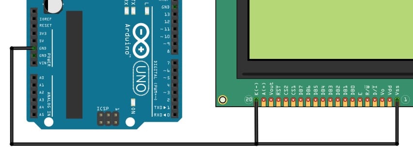
Ground connections bring common reference for both LCD and the Arduino. I will always recommend starting with the Ground connection first.
I have connected the GND pin of the Arduino to the VSS pin and BackLight LED’s cathode pin.
Step 3: LCD Chip select pin connection
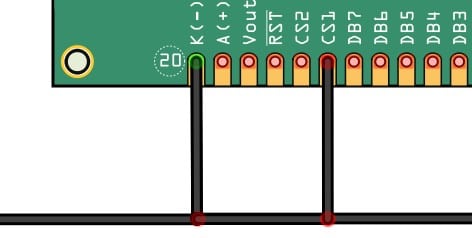
Connect CS1, the chip-select line of the LCD, to the Ground as well. Connecting to the Ground pin keeps the LCD controller always enabled. You can leave the CS2 unconnected.
Step 4: SPI SCLK connection between LCD and the UNO
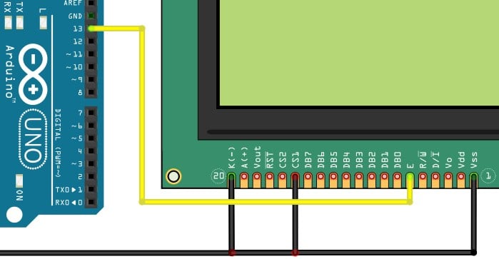
The Pin 13 of the Arduino goes to the “E” pin on the LCD module.
Step 5: SPI Chip select connection between the LCD and the Arduino UNO
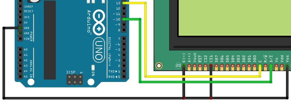
The green cable connects the Arduino UNO’s SPI Slave select pin to the LCD controller SPI CS line (D/I) in the board.
Step 6: SPI MOSI line connection
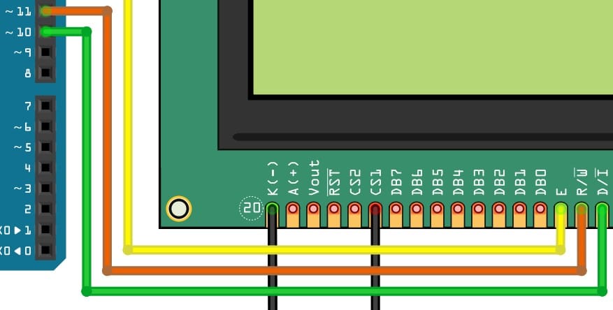
The orange cable connects the Arduino UNO’s SPI MOSI pin to the LCD controller’s SPI R/W# pin.
Step 7: LCD controller power supply and LED backlight connection
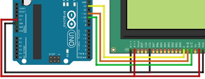
The red cable connects the Arduino UNO’s 5 V to the LCD board. You also have to power the backlight LED.
In our case, we are also connecting the LED pin directly to the 5 V line.
If you want to control the backlight, you can connect any other GPIO pin to the LED Anode pin.
You can use GPIO to turn on or turn off the backlight.
This will help you save power by turning off the backlight when it is unnecessary.
Step 8: LCD contrast setting option
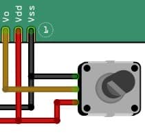
You can control the LCD’s contrast by connecting a potentiometer between 5 V and GND. You can do this using the center pin of the potentiometer.
Connect the potentiometer’s moving pin (usually the center pin) to the V0 pin of the LCD board. The contrast can be increased or decreased by turning the potentiometer to the right or the left.
After you program the Arduino and make all the connections, you may see nothing on display. Turn the potentiometer until you can see the pixels.
Step 9: Complete Arduino and the 128×64 Graphic LCD connection overview
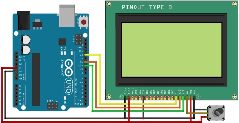
Congratulations! You have completed all the necessary connections between the LCD and Arduino UNO.
In the coming section, we will see how you can use standard libraries available to display the data onto the LCD.
Displaying An Image On The LCD
To display the image on the LCD, you have to follow specific steps. Reduce the image to pixels needed. If you plan to show the image on the entire screen, you must reduce the image size to 128×64 pixels.
If you must display the image on half of the screen, you have to reduce the image to 64×64 pixels.
You have to save the image as a monochrome bitmap using any image editing software.
Since it will be a monochrome image, You will be able to read the image in hex format.
It is very easy to use the GIMP software for this purpose.
The GIMP tool can export the image in X bitmap format. The advantage is that you can use any notepad software and view the hex data.
My personal preference is Notepad++. It is an open-source text editor.
The below Arduino code displays the image which you have just created.
The Complete Arduino Code
Open the Arduino IDE and click on the “File” option. Under the file options, select “New.”
#include "Arduino.h"
#include "U8g2lib.h"

#ifdef U8X8_HAVE_HW_SPI
#include "SPI.h"
#endif
#ifdef U8X8_HAVE_HW_I2C
#include "Wire.h"
#endif

// 'TheOffice', 128x64px, source: //https://www.electronicshub.org/interfacing-128x64-graphical-lcd-with-arduino/

static const unsigned char myBitmap [] PROGMEM = {

  0xf8, 0xff, 0xff, 0xff, 0xff, 0xff, 0xff, 0xff, 0xff, 0xff, 0xff, 0xff,
  0xff, 0xff, 0xff, 0x3f, 0x3e, 0x00, 0x00, 0x00, 0x00, 0x00, 0x00, 0x00,
  0x00, 0x00, 0x00, 0x00, 0x00, 0x00, 0x00, 0x78, 0x06, 0x00, 0x00, 0x00,
  0x00, 0x00, 0x00, 0x00, 0xc0, 0xff, 0xff, 0xff, 0xff, 0xff, 0xff, 0xc7,
  0x03, 0x00, 0x00, 0x00, 0x00, 0x00, 0x00, 0x00, 0xf0, 0xff, 0xff, 0xff,
  0xff, 0xff, 0xff, 0x9f, 0x03, 0x00, 0x00, 0x00, 0x00, 0x00, 0x00, 0x00,
  0x38, 0x00, 0x00, 0x00, 0x00, 0x00, 0x00, 0xb8, 0x03, 0x00, 0x00, 0x00,
  0x00, 0x00, 0x00, 0x00, 0x18, 0x00, 0x00, 0x00, 0x00, 0x00, 0x00, 0xb0,
  0x01, 0x00, 0x00, 0x00, 0x00, 0x00, 0x00, 0x00, 0x08, 0x00, 0x00, 0x00,
  0x00, 0x00, 0x00, 0xb0, 0x01, 0x00, 0x00, 0x00, 0x00, 0x00, 0x00, 0x00,
  0x08, 0x00, 0x00, 0x00, 0x00, 0x00, 0x00, 0xb0, 0x01, 0x00, 0x00, 0x00,
  0x00, 0x00, 0x00, 0x00, 0x08, 0x00, 0x3e, 0x00, 0x00, 0x00, 0x00, 0xb0,
  0x01, 0x00, 0x00, 0x00, 0x00, 0x00, 0x00, 0x00, 0x08, 0x00, 0x3f, 0x00,
  0x00, 0x00, 0x00, 0xb0, 0x01, 0x00, 0x00, 0x00, 0x00, 0x00, 0x00, 0x00,
  0x08, 0x80, 0x7f, 0x00, 0x00, 0x00, 0x00, 0xb0, 0x01, 0x00, 0x00, 0x00,
  0x00, 0x00, 0x00, 0x00, 0x08, 0x80, 0x7f, 0x00, 0x00, 0x00, 0x00, 0xb0,
  0x01, 0x00, 0x00, 0x00, 0x00, 0x00, 0x00, 0x00, 0x08, 0x80, 0x7f, 0x00,
  0x00, 0x00, 0x00, 0xb0, 0x01, 0x00, 0x00, 0x00, 0x00, 0x00, 0x00, 0x00,
  0x08, 0x00, 0x7f, 0x00, 0x00, 0x00, 0x00, 0xb0, 0x01, 0x00, 0x00, 0x00,
  0x00, 0x00, 0x00, 0x00, 0x08, 0x00, 0x3f, 0x00, 0x00, 0x00, 0x00, 0xb0,
  0x01, 0x00, 0x00, 0x00, 0x00, 0x00, 0x00, 0x00, 0x08, 0xc0, 0x7f, 0x00,
  0x00, 0x00, 0x00, 0xb0, 0x01, 0x00, 0x00, 0x00, 0x00, 0x00, 0x00, 0x00,
  0x08, 0xf0, 0xff, 0x03, 0x00, 0x00, 0x00, 0xb0, 0x01, 0x00, 0x00, 0x00,
  0x00, 0x00, 0x00, 0x00, 0x08, 0xf8, 0xff, 0x07, 0x00, 0x00, 0x7c, 0xb0,
  0x01, 0x00, 0x00, 0x00, 0x00, 0x00, 0x00, 0x00, 0x08, 0xf8, 0xff, 0x07,
  0x00, 0x00, 0xfe, 0xb0, 0x01, 0x00, 0x00, 0x00, 0x00, 0x00, 0x00, 0x00,
  0x08, 0xf8, 0xff, 0x07, 0x00, 0x00, 0xfe, 0xb0, 0x01, 0x00, 0x00, 0x00,
  0x00, 0x00, 0x00, 0x00, 0x08, 0xf8, 0xff, 0x07, 0x00, 0x00, 0xfe, 0xb0,
  0x81, 0xff, 0x1d, 0x00, 0x00, 0x00, 0x00, 0x00, 0x08, 0xf8, 0xff, 0x0f,
  0x00, 0x00, 0xfe, 0xb0, 0x81, 0xff, 0x1d, 0x00, 0x00, 0x00, 0x00, 0x00,
  0x08, 0xf8, 0xff, 0x0f, 0x00, 0x00, 0xfe, 0xb0, 0x81, 0xff, 0x1d, 0x00,
  0x00, 0x00, 0x00, 0x00, 0x08, 0xfc, 0xff, 0x0f, 0x00, 0x00, 0xfe, 0xb0,
  0x01, 0x38, 0xdc, 0xc0, 0x00, 0x00, 0x00, 0x00, 0x08, 0xfc, 0xff, 0x0f,
  0x00, 0x00, 0x7c, 0xb0, 0x01, 0x38, 0xfc, 0xf3, 0x03, 0x00, 0x00, 0x00,
  0x08, 0xfc, 0xff, 0x0f, 0x00, 0x00, 0x38, 0xb0, 0x01, 0x38, 0xfc, 0xfb,
  0x07, 0x00, 0x00, 0x00, 0x08, 0xfc, 0xff, 0x0f, 0x00, 0x00, 0xfc, 0xb0,
  0x01, 0x38, 0x9c, 0x3b, 0x07, 0x00, 0x00, 0x00, 0x08, 0xfc, 0xff, 0x07,
  0x00, 0x00, 0xfe, 0xb0, 0x01, 0x38, 0x9c, 0xfb, 0x07, 0x00, 0x00, 0x00,
  0x08, 0xfc, 0xff, 0x07, 0x00, 0x00, 0xfe, 0xb7, 0x01, 0x38, 0x9c, 0xfb,
  0x07, 0x00, 0x00, 0x00, 0x08, 0xfc, 0xff, 0x07, 0x00, 0x00, 0xfe, 0xb7,
  0x01, 0x38, 0x9c, 0x3b, 0x07, 0x00, 0x00, 0x00, 0x08, 0xfc, 0xff, 0x07,
  0x00, 0x00, 0xfe, 0xb7, 0x01, 0x38, 0x9c, 0xfb, 0x07, 0x00, 0x00, 0x00,
  0x08, 0xfe, 0xff, 0x07, 0x00, 0x00, 0xff, 0xb7, 0x01, 0x38, 0x9c, 0xf3,
  0x03, 0x00, 0x00, 0x00, 0x08, 0xfe, 0xff, 0x07, 0x00, 0x80, 0xff, 0xb7,
  0x01, 0x00, 0x00, 0xc0, 0x00, 0x00, 0x00, 0x00, 0xc8, 0xff, 0xff, 0x00,
  0x00, 0xc0, 0xff, 0xb6, 0x01, 0x00, 0x00, 0x00, 0x00, 0x00, 0x00, 0x00,
  0xc8, 0xff, 0xff, 0x00, 0x00, 0xe0, 0xff, 0xb6, 0x01, 0x00, 0x00, 0x00,
  0x00, 0x00, 0x00, 0x00, 0xc8, 0xff, 0xff, 0x00, 0x00, 0xfe, 0xff, 0xb6,
  0x01, 0x00, 0x00, 0x00, 0x00, 0x00, 0x00, 0x00, 0xc8, 0xff, 0xff, 0x00,
  0xc0, 0xff, 0xff, 0xb6, 0x01, 0x00, 0x00, 0x00, 0x00, 0x00, 0x00, 0x00,
  0xc8, 0xff, 0xff, 0x00, 0xe0, 0xff, 0xff, 0xb6, 0x01, 0xf8, 0x07, 0xbe,
  0xff, 0x00, 0x00, 0x00, 0xc8, 0xff, 0xff, 0x00, 0xe0, 0x7f, 0xff, 0xb7,
  0x01, 0xfc, 0x1f, 0xbf, 0xff, 0x00, 0x00, 0x00, 0xc8, 0xff, 0xff, 0xfc,
  0xff, 0x0f, 0xff, 0xb7, 0x01, 0xfe, 0x1f, 0xbf, 0xff, 0x00, 0x00, 0x00,
  0xc8, 0xff, 0xff, 0xfc, 0xff, 0xef, 0xff, 0xb7, 0x01, 0x1f, 0x3e, 0x8f,
  0x03, 0x00, 0x00, 0x00, 0xc8, 0xff, 0xff, 0xc0, 0x01, 0xfe, 0xff, 0xb7,
  0x01, 0x0f, 0xbc, 0xff, 0xef, 0xf0, 0x87, 0x1f, 0xc8, 0xff, 0xff, 0xc0,
  0x01, 0xff, 0xff, 0xb7, 0x01, 0x0f, 0xbc, 0xff, 0xef, 0xf8, 0xcf, 0x3f,
  0xc8, 0xff, 0xff, 0xc0, 0x01, 0xff, 0xff, 0xb7, 0x01, 0x0f, 0xb8, 0xff,
  0xef, 0xfc, 0xef, 0x3f, 0xc8, 0xff, 0xff, 0xc0, 0x01, 0xff, 0x7f, 0xb7,
  0x01, 0x0f, 0x38, 0x8f, 0xe3, 0x3c, 0xef, 0x79, 0x08, 0xc0, 0x7f, 0xc0,
  0x81, 0xff, 0x1f, 0xb7, 0x01, 0x0f, 0x3c, 0x8f, 0xe3, 0x3c, 0xe0, 0x7f,
  0x08, 0xc0, 0x7f, 0xc0, 0x81, 0xef, 0xff, 0xb7, 0x01, 0x0f, 0x3c, 0x8f,
  0xe3, 0x1c, 0xe0, 0x7f, 0x08, 0xc0, 0x7f, 0xc0, 0x81, 0xef, 0xff, 0xb7,
  0x01, 0x1f, 0x3c, 0x8f, 0xe3, 0x3c, 0xe6, 0x7f, 0x08, 0xc0, 0x7f, 0xc0,
  0x81, 0xe7, 0xff, 0xb7, 0x01, 0x3e, 0x3e, 0x8f, 0xe3, 0x3c, 0xef, 0x79,
  0x08, 0x80, 0x7b, 0xc0, 0xc1, 0x67, 0x00, 0xb7, 0x01, 0xfe, 0x1f, 0x8f,
  0xe3, 0xfc, 0xef, 0x7f, 0x08, 0x80, 0x33, 0xc0, 0xc1, 0x67, 0x00, 0xb7,
  0x01, 0xfc, 0x0f, 0x8f, 0xe3, 0xf8, 0xcf, 0x3f, 0x08, 0x00, 0x00, 0xc0,
  0xc1, 0x67, 0x00, 0xb7, 0x01, 0xf8, 0x07, 0x8f, 0xe3, 0xf0, 0xc7, 0x1f,
  0x08, 0x00, 0x00, 0xc0, 0xe1, 0x63, 0x00, 0xb7, 0x01, 0x00, 0x00, 0x00,
  0x00, 0x00, 0x00, 0x00, 0x08, 0x00, 0x00, 0xc0, 0xe1, 0x63, 0x00, 0xb7,
  0x01, 0x00, 0x00, 0x00, 0x00, 0x00, 0x00, 0x00, 0x08, 0x00, 0x00, 0xc0,
  0xe1, 0x61, 0x00, 0xb7, 0x01, 0x00, 0x00, 0x00, 0x00, 0x00, 0x00, 0x00,
  0x08, 0x00, 0x00, 0xc0, 0xe1, 0x61, 0x00, 0xb7, 0x01, 0x00, 0x00, 0x00,
  0x00, 0x00, 0x00, 0x00, 0x08, 0x00, 0x00, 0xc0, 0xe1, 0x61, 0x00, 0xb7,
  0x01, 0x00, 0x00, 0x00, 0x00, 0x00, 0x00, 0x00, 0x08, 0x00, 0x00, 0xc0,
  0xe1, 0x60, 0x00, 0xb2, 0x01, 0x00, 0x00, 0x00, 0x00, 0x00, 0x00, 0x00,
  0x18, 0x00, 0x00, 0x00, 0x00, 0x00, 0x00, 0xb0, 0x03, 0x00, 0x00, 0x00,
  0x00, 0x00, 0x00, 0x00, 0x18, 0x00, 0x00, 0x00, 0x00, 0x00, 0x00, 0xb0,
  0x03, 0x00, 0x00, 0x00, 0x00, 0x00, 0x00, 0x00, 0x78, 0x00, 0x00, 0x00,
  0x00, 0x00, 0x00, 0xbc, 0x03, 0x00, 0x00, 0x00, 0x00, 0x00, 0x00, 0x00,
  0xe0, 0xff, 0xff, 0xff, 0xff, 0xff, 0xff, 0xcf, 0x06, 0x00, 0x00, 0x00,
  0x00, 0x00, 0x00, 0x00, 0x00, 0x00, 0x00, 0x00, 0x00, 0x00, 0x00, 0xe0,
  0xfc, 0xff, 0xff, 0xff, 0xff, 0xff, 0xff, 0xff, 0xff, 0xff, 0xff, 0xff,
  0xff, 0xff, 0xff, 0x7f
};


U8G2_ST7920_128X64_F_SW_SPI u8g2(U8G2_R0, /* clock=*/ 13, /* data=*/ 11, /* CS=*/ 10, /* reset=*/ 8);


void draw(void)
{
  u8g2.drawXBMP( 0, 0, 128, 64, myBitmap);
}


void setup()
{
  // put your setup code here, to run once:
  u8g2.begin();
  u8g2.clearBuffer();
}

void loop()
{
  // put your main code here, to run repeatedly:
  u8g2.firstPage();
  do
  {
    draw();
  } while (u8g2.nextPage());

  delay(1000);
}
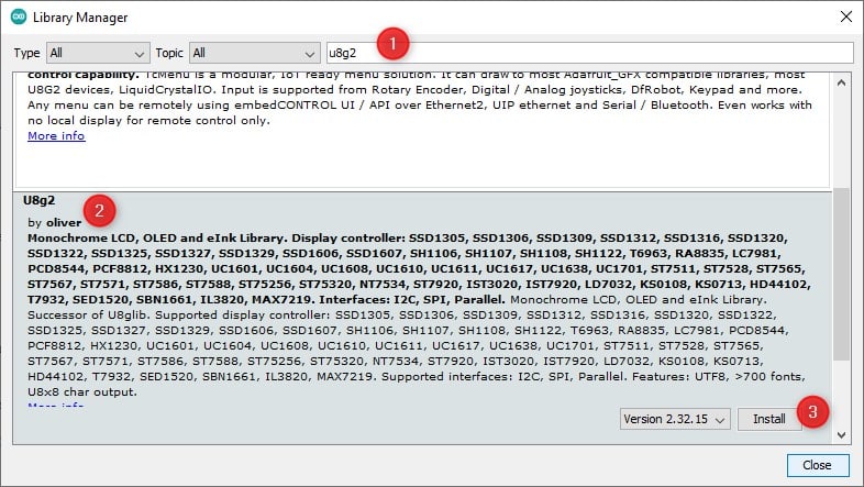
You have to install the u8g2 library. Go to the “Tools” option in the Arduino IDE, and select “Manage Libraries.”
Search for u8g2 in the search bar. Locate the library in the results and install it.
In order to update the code to the new image, you have just created, please replace the hex code with the ones you have created.
The total number of pixels is 8192. So the number of bytes will be 8192/8 = 1024 bytes for an image on full screen.
FAQs About The 128×64 Graphics LCD And Arduino Project
There are frequently asked questions about the 128×64 LCD projects. I have created a list of questions and answered them to my best knowledge.
I will be happy if you find the answers to your questions. If you have further questions, kindly drop them in the comments section.
1) How to connect a graphic LCD to an Arduino?
You can connect the LCD to the Arduino using several interfaces. For example, you can use SPI (3-wire or a 4-wire interface) or parallel bus interfaces (6800 or an 8080 interface).
All graphic LCD needs an LCD controller IC. It would help if you first found the board’s LCD controller IC.
Later, you should see the correct library code, if possible.
2) How does graphic LCD work?
The graphic display either blocks the light or allows the light to pass through each pixel area. Each small pixel can be polarised or depolarised based on its voltage.
There are various types of displays (Transmissive, transflective and reflective). A reflective display depends on the external light to read the display. The Transmissive displays enable a backlight to be present.
In some displays, there will be row addressing and column addressing for each cell in the matrix. In a monochrome display, each cell will have a value stored in a transistor (either a one or a 0).
The good news is that we must communicate the values we want to write in the display.
We dont have to worry about how the pixels are driven individually. The data can be represented by 1s or 0s.
3) How do you write data to the Graphic LCD controller?
Here is the block diagram overview of how the Arduino UNO writes the data to the LCD controller IC.
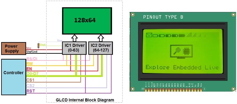
The 128×64 LCD means it has 128 pixels on the X axis and 64 on the Y axis. Further, the data lines are 8-bit wide. It means you will take care of all 64 bits in blocks of 8 bits at once.
You can use the Chip select lines to select the right IC. For more information, you can refer to one example here.
Conclusion
In this article, I have shown you how to load any image or graphics on the LCD.
I have covered a step-by-step connection guide to complete the connections between the Arduino UNO and the 128×64 Graphics LCD.
I will gladly help you with your projects if you have any questions.
Please post your questions in the comments section. I have used the graphics LCD to build a simple game.
I am sure your creativity will get wings when you have a graphical LCD instead of a character LCD.
I will be excited to know what you build next with the Graphics LCD.
You can share your projects in the comments section. I will be happy to get to know your projects too.
Do you have any suggestions for the next article? Which project do you think I should write about next?
What other topics are you interested in reading? Kindly let me know in the comments.
Please share the article with your friends.

I am Puneeth. I love tinkering with open-source projects, Arduino, ESP32, Pi and more. I have worked with many different Arduino boards and currently I am exploring, Arduino powered LoRa, Power line communication and IoT.
TDHofstetter
Friday 1st of December 2023
Your #includes are empty. That source cannot possibly be compiled.
Stefan Maetschke
Saturday 2nd of December 2023
That is an annoying issue with the syntax highlighter, which fails for the angular brackets :( Fixed, by replacing angular brackets with quotes. Thanks for letting me know.
Ayhan
Friday 16th of June 2023
Hello Friends, I have 2 arduino screens in my hand, I have searched a lot on the same internet, but I could not find a sample study such as clock or heat sensor according to this screen, if there is a trial purpose according to this screen. I searched a lot and couldn't find if there is a prefix with the codes I can run. I found a few on youtube. I couldn't run them. good luck
Arduino code: WG12864C1-TMI-V#N
Display Properties: bottom line
ozdisan.com
WG12864C1-TMI-V#N 1 LCD MOD GRAP 128*64 LED B.LIGHT STN NEG BL NEG VOL