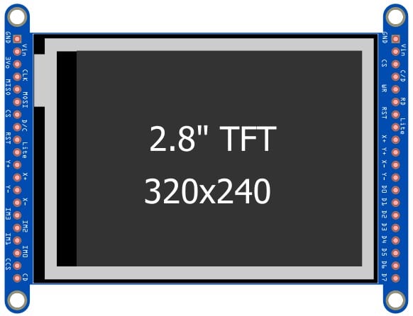
In this article, we will interface a TFT display with a touch interface. This tutorial uses a 2.8-inch LCD with a capacitive touch interface.
The touch option enables you to interact with the project efficiently.
If you have the menu selection option such as increasing the volume or turning on or off a light, the touch option helps a lot.
You can find a TFT Touch display best suited to HMIs where the user can do specific settings or make some selections.
You can build a Timer project where the user can set the time right on the LCD. Other examples include interactive games, controlling thermostats, etc.
I will briefly introduce the Touch section, Pinouts of the 2.8-inch TFT display, and details of the connection diagram.
At the end of the article, I will share a working code example and an online simulation link for the project.
Let’s begin!
Components Needed To Build Arduino And TFT Display With Touch Project
Hardware Components
- Dupont wire x 1 set
- Arduino USB cable (for powering Arduino and programming) x 1
- Breadboard x 1 (optional)
- BergStick Connectors (optional
Software
Makerguides.com is a participant in the Amazon Services LLC Associates Program, an affiliate advertising program designed to provide a means for sites to earn advertising fees by advertising and linking to products on Amazon.com.
Basics of TFT Display With Touch Interface
This article is part of our series on the different types of displays that you can use with Arduino, so if you’re weighing up the options, then do check out our guide to the best displays to use with Arduino.
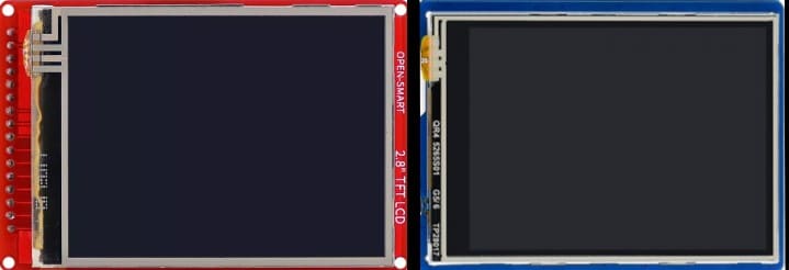
The TFT displays come in two variants: With touch and without touch. The modules with touch come with an additional layer of transparent touch screen.
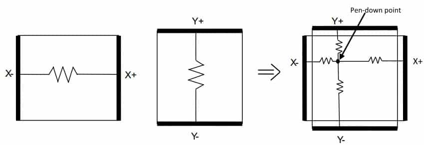
Touch sensing can be either resistive type or capacitive type. The resistive types need the pressure to be applied on the screen to detect the touch.
The capacitive screen is more sensitive, and a simple touch is sufficient.
Depending on the display you are using, the pin numbering will change.
I will provide the pin details for two displays here: one for a resistive type and another one for a capacitive type.
The pinouts for the display and the SD card remain the same. Only pinouts related to the touch sensor will change depending on whether the module has a resistive or capacitive type touch sensor.
Resistive Touch Controller
You must apply pressure on the screen to make the touch work. You will find both analog and digital resistive touch controllers.
The analog type helps you even to detect the pressure on the touch.
The digital resistive sensors only can say whether a touch is there or not.
An example of the resistive touch controller IC is STMPE610. You can find the datasheet here.
The main features of the resistive touch controller ICs are
- Integrated 4-wire touch controller
- Supports both SPI and I2C interface
- Ultra-low quiescent current
- Wakeup feature on each GPIO
- GPIO expander with 6 GPIOs
- 12- bit Analog to Digital Converter
Capacitive Touch Controller
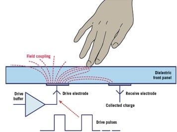
The capacitive touch works on the capacitance change principle. You change the capacitance value slightly wherever you touch the screen.
The touch controller detects this change in the capacitance.
The controller will declare it a touch based on the previously decided thresholds.
The electric field gets coupled through your hand when you touch the screen. This change is the electric field reflected as the change in the capacitance.
The touch screen’s lifetime will be better than the resistive touch screen due to the principle of operation, though they are slightly expensive.
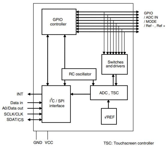
An example of the capacitive touch controller IC found in the TFT display modules is FT6206.
You can find the datasheet here. The block diagram is shown below.
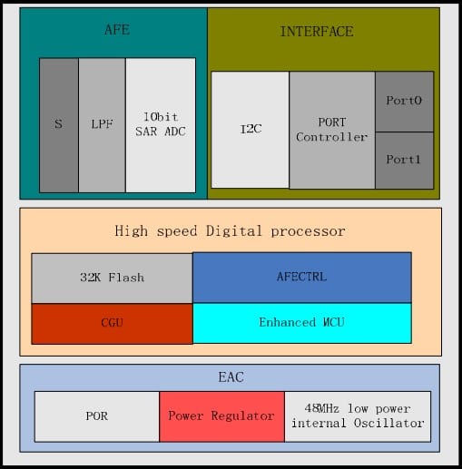
The features of the FT6206 capacitive touch controller IC are given below:
- Auto-calibration so that change in the environment condition will not influence the capacitive measurement
- Supports up to 28 channels
- I2C interface for host communication
- The update rate of 100 Hz (10 ms update)
- Internal ADC and filter
- Multiple power modes
The Pinout of TFT Touch controller
Example 1 – TFT 2.8-inch Display With Touch From Adafruit
| Pin Name | Pin Type | Description |
| GND | Power Pin | Ground pin. Return current path for all the power and the signals |
| VIN | Power Pin | Power supply input pin for the TFT display controller and a touch controller |
| 3V0 | Power Pin | |
| CLK | ICSP CLK | ICSP SPI Clock. You can access the pin by locating the ICSP header pin on the Arduino. You can wire this pin to the digital pin 13 of the Arduino using a jumper |
| MISO | ICSP MISO | ICSP hardware SPI MISO line. You can access the pin by locating the ICSP header pin on the Arduino. You can wire this pin to the digital pin 12 of the Arduino using a jumper |
| MOSI | ICSP MOSI | ICSP hardware SPI MOSI line. You can access the pin by locating the ICSP header pin on the Arduino. You can wire this pin to the digital pin 11 of the Arduino using a jumper |
| CS | Chip Select | TFT Chip select line. Arduino uses this line to select the TFT display controller. Digital pin 10 of the Arduino |
| D/C | Data Command Select | The Arduino uses this line to inform whether the data on the SPI is data or a command. Digital pin 9 of the Arduino |
| RST | Reset Line | Resets the touch controller |
| SDA | I2C data line | The I2C data line used to communicate with the touch controller |
| SCL | I2C clock line | The I2C clock line used to communicate with the touch controller |
| X+ | Touch pins | Resistive touch pin line |
| X- | Touch pins | Resistive touch pin line |
| Y+ | Touch pins | Resistive touch pin line |
| Y- | Touch pins | Resistive touch pin line |
Example 2 – TFT 2.8-inch Display With Touch From ILI9341
| Pin Number | Pin Name | Description |
| 1 | VCC | Ground pin. Return current path for all the power and the signals |
| 2 | GND | Power supply input pin for the TFT display controller, and a touch controller |
| 3 | CS | Chip select |
| 4 | RST | Reset line |
| 5 | D/C | Data/Command Pin |
| 6 | MOSI | SPI data (Master Out Slave In) This is input pin of the LCD controller and output pin for the Arduino |
| 7 | SCK | SPI Clock Pin. This is the output pin of the Arduino |
| 8 | LED | Voltage for LED backlight |
| 9 | MISO | SPI data (Master In Slave Out) This is the output pin of the LCD controller and the input pin for the Arduino |
| 10 | SCL | I2C Serial Clock line – I2C interface for the touch controller. |
| 11 | SDA | I2C Serial Data line – I2C interface for the touch controller |
Step-By-Step Instructions To Connect A TFT display With Touch To An Arduino
In this section, I will give you step-by-step instructions to complete the needed connection between the Arduino and the TFT display.
The connections related to the touch controller will differ depending on whether you use a capacitive or a resistive touch controller.
Other than this, the remaining connections, such as the SD card or the TFT display controller, remain the same.
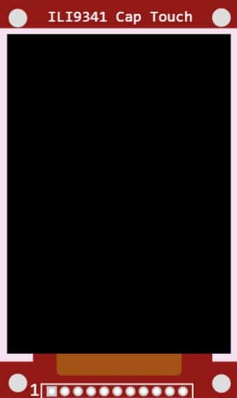
In this example, we will use a 2.8-inch capacitive touch display and interface it with an Arduino.
In the later sections, I will provide an example code, a working simulation link, and FAQs on the Arduino TFT display with touch projects.
How To Connect The TFT Display With Touch To The Arduino UNO?
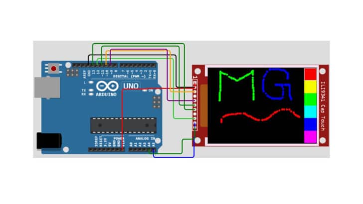
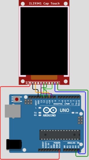
Here are the details required to complete the Arduino and the 2.8-inch TFT display with touch. The final result resembles the connection shown below.
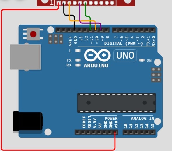
Step 1: Let us begin with the Ground connection
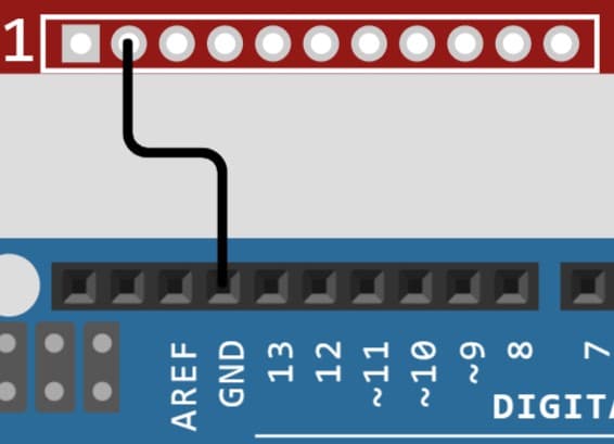
It is a good practice to start the connections with the GND connection first. Pin 2 of the LCD goes to the GND pin on the Arduino.
You can choose any of the GND pins available to complete the connection.
Step 2: Connect the CS pin
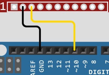
Connect the CS pin of the LCD (pin 3) to Pin 10 of the Arduino. CS can be any GPIO pin on the Arduino.
Step 3: Connect the Power Pin
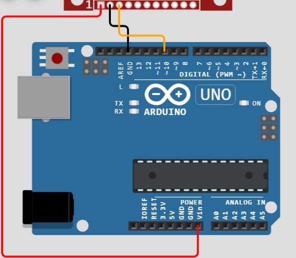
Connect Pin 1 of the LCD to the VIN pin of the Arduino.
Step 4: C/S Connection between LCD and the Arduino

Connect pin 9 on the Arduino UNO to Pin 5 of the LCD module.
Step 5: LCD MOSI Connection between Arduino and LCD Module
Connect pin 6 of the LCD to Pin 11 of the Arduino UNO. This is the MOSI pin of the SPI protocol. The data direction is from Arduino to the LCD.
Step 6: LCD SCK SPI line connection

Complete the connection between Pin 13 of the Arduino and the LCD module’s Pin 7 (SCK line).
Step 7: LCD MISO connection

Connect the LCD board’s pin 9 to Pin 12 of the Arduino. SPI MISO pin is the LCD module’s output pin and the Arduino’s input pin.
Step 8: I2C SCL Pin Connection
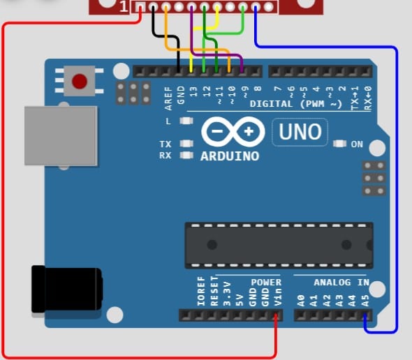
The SCL pin of the Arduino goes to Pin 10 of the LCD. A5 is the SCL pin on the Arduino.
Step 9: I2C SDA Pin Connection
The SDA pin of the Arduino goes to Pin 11 of the LCD. A4 is the SDA pin on the Arduino.
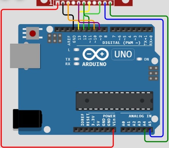
Step 10: Complete Arduino and TFT Display connection overview
Congratulations! You have completed the connection needed to interface the LCD and the Touch controller with the Arduino.
Arduino Code Example For The 2.8-Inch TFT Display With Touch
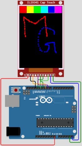
In this section, I will take you through a simple Arduino program that allows you to select a brush color and draw on the screen.
This is a fantastic way to introduce someone to the benefit of having a touch screen with a color display!
The Arduino code below provides six color options to choose from. Later, you can draw using your finger or a stylus in the empty area.
The Complete Arduino Code
Open the Arduino IDE and click on the “File” option. Under the file options, select “New.”
#include "Adafruit_GFX.h"    // Core graphics library
#include "SPI.h"       // this is needed for display
#include "Adafruit_ILI9341.h"
#include "Wire.h"      // this is needed for FT6206
#include "Adafruit_FT6206.h"

// The FT6206 uses hardware I2C (SCL/SDA)
Adafruit_FT6206 ctp = Adafruit_FT6206();

// The display also uses hardware SPI, plus #9 & #10
#define TFT_CS 10
#define TFT_DC 9
Adafruit_ILI9341 tft = Adafruit_ILI9341(TFT_CS, TFT_DC);

// Size of the color selection boxes and the paintbrush size
#define BOXSIZE 40
#define PENRADIUS 3
int oldcolor, currentcolor;

void setup(void) {
  while (!Serial);     // used for leonardo debugging

  Serial.begin(115200);
  Serial.println(F("Cap Touch Paint!"));

  tft.begin();

  if (! ctp.begin(40)) {  // pass in 'sensitivity' coefficient
    Serial.println("Couldn't start FT6206 touchscreen controller");
    while (1);
  }

  Serial.println("Capacitive touchscreen started");

  tft.fillScreen(ILI9341_BLACK);

  // make the color selection boxes
  tft.fillRect(0, 0, BOXSIZE, BOXSIZE, ILI9341_RED);
  tft.fillRect(BOXSIZE, 0, BOXSIZE, BOXSIZE, ILI9341_YELLOW);
  tft.fillRect(BOXSIZE*2, 0, BOXSIZE, BOXSIZE, ILI9341_GREEN);
  tft.fillRect(BOXSIZE*3, 0, BOXSIZE, BOXSIZE, ILI9341_CYAN);
  tft.fillRect(BOXSIZE*4, 0, BOXSIZE, BOXSIZE, ILI9341_BLUE);
  tft.fillRect(BOXSIZE*5, 0, BOXSIZE, BOXSIZE, ILI9341_MAGENTA);

  // select the current color 'red'
  tft.drawRect(0, 0, BOXSIZE, BOXSIZE, ILI9341_WHITE);
  currentcolor = ILI9341_RED;
}

void loop() {
  // Wait for a touch
  if (! ctp.touched()) {
    return;
  }

  // Retrieve a point
  TS_Point p = ctp.getPoint();

 /*
  // Print out raw data from screen touch controller
  Serial.print("X = "); Serial.print(p.x);
  Serial.print("\tY = "); Serial.print(p.y);
  Serial.print(" -> ");
 */

  // flip it around to match the screen.
  p.x = map(p.x, 0, 240, 240, 0);
  p.y = map(p.y, 0, 320, 320, 0);

  // Print out the remapped (rotated) coordinates
  Serial.print("("); Serial.print(p.x);
  Serial.print(", "); Serial.print(p.y);
  Serial.println(")");


  if (p.y < BOXSIZE) {
     oldcolor = currentcolor;

     if (p.x < BOXSIZE) {
       currentcolor = ILI9341_RED;
       tft.drawRect(0, 0, BOXSIZE, BOXSIZE, ILI9341_WHITE);
     } else if (p.x < BOXSIZE*2) {
       currentcolor = ILI9341_YELLOW;
       tft.drawRect(BOXSIZE, 0, BOXSIZE, BOXSIZE, ILI9341_WHITE);
     } else if (p.x < BOXSIZE*3) {
       currentcolor = ILI9341_GREEN;
       tft.drawRect(BOXSIZE*2, 0, BOXSIZE, BOXSIZE, ILI9341_WHITE);
     } else if (p.x < BOXSIZE*4) {
       currentcolor = ILI9341_CYAN;
       tft.drawRect(BOXSIZE*3, 0, BOXSIZE, BOXSIZE, ILI9341_WHITE);
     } else if (p.x < BOXSIZE*5) {
       currentcolor = ILI9341_BLUE;
       tft.drawRect(BOXSIZE*4, 0, BOXSIZE, BOXSIZE, ILI9341_WHITE);
     } else if (p.x <= BOXSIZE*6) {
       currentcolor = ILI9341_MAGENTA;
       tft.drawRect(BOXSIZE*5, 0, BOXSIZE, BOXSIZE, ILI9341_WHITE);
     }

     if (oldcolor != currentcolor) {
        if (oldcolor == ILI9341_RED)
          tft.fillRect(0, 0, BOXSIZE, BOXSIZE, ILI9341_RED);
        if (oldcolor == ILI9341_YELLOW)
          tft.fillRect(BOXSIZE, 0, BOXSIZE, BOXSIZE, ILI9341_YELLOW);
        if (oldcolor == ILI9341_GREEN)
          tft.fillRect(BOXSIZE*2, 0, BOXSIZE, BOXSIZE, ILI9341_GREEN);
        if (oldcolor == ILI9341_CYAN)
          tft.fillRect(BOXSIZE*3, 0, BOXSIZE, BOXSIZE, ILI9341_CYAN);
        if (oldcolor == ILI9341_BLUE)
          tft.fillRect(BOXSIZE*4, 0, BOXSIZE, BOXSIZE, ILI9341_BLUE);
        if (oldcolor == ILI9341_MAGENTA)
          tft.fillRect(BOXSIZE*5, 0, BOXSIZE, BOXSIZE, ILI9341_MAGENTA);
     }
  }
  if (((p.y-PENRADIUS) > BOXSIZE) && ((p.y+PENRADIUS) < tft.height())) {
    tft.fillCircle(p.x, p.y, PENRADIUS, currentcolor);
  }
}
Note:
- Here is the link to the simulation – where you can actively change the code and see the results in action. You can save the project and share the links with others too.
- Please refer to this guide to install the required libraries from Adafruit.
FAQs About The Arduino 2.8-inch TFT Color Display With Touch
I have compiled a list of questions most frequently asked regarding the TFT and the touch usage with Arduino. I have answered them in one place.
If you still have questions, I will be glad to hear them in the comments section.
1) How to use the TFT touch screen with Arduino?
Some dedicated controllers can help Arduino detect the screen’s finger touch easily. One example is an FT6206 which can support small to medium-sized screens with up to 28 sensors.
Arduino needs to only communicate with IC (usually over I2C or SPI) to understand the touch position
In this article, I have covered one example with the simulation, which you can try out.
Also, refer to the basics section to learn more about the touch controllers (both resistive and capacitive).
2) Are TFT displays touch screens?
No. TFT displays are not touch screens by default. You can have display modules with touch functions as well.
The touch panel is a dedicated layer on the top of the display, which is handled by an independent touch controller IC.
3) What does TFT mean in Touch screen?
TFT stands for Thin Film Technology, a label given to a class of LCDs supporting monochrome and color displays.
Although there are many TFT touch screens in the market, The TFT name and touch technology have no relation.
4) Is the TFT display better than AMOLED?
AMOLEDs are brighter and more power efficient than TFT displays. The viewing angles of AMOLEDs are better for outdoors as well. The TFTs are cheaper.
Recent advancements have made AMOLEDs more affordable for embedded systems.
Conclusion
I have taken you through the TFT display module basics with a touch screen in this article.
I am sure you will be eager to try out your applications of touch and display together in your following projects!
I am confident that the article was easy to follow. I have used TFT display with touch for an HMI project which controls the thermostat in my hobby projects to learn more about the OT system (open Therm)
Feel free to share your projects in the comments section. I will be happy to learn about projects you have built using TT touch screen modules.
Please leave a link to your projects in the comments!
Which article would be the one you would like to read about next?
Please let me know in the comments section.
Share the articles with your friends and fellow Arduino enthusiasts!

I am Puneeth. I love tinkering with open-source projects, Arduino, ESP32, Pi and more. I have worked with many different Arduino boards and currently I am exploring, Arduino powered LoRa, Power line communication and IoT.