
In this tutorial you will learn how to use the 74HC595 Shift Register to expand the number of outputs of your Arduino.
The popular Arduino UNO has 14 GPIO pins you can use to output (or input) data. For many cases this is a sufficient number of output pins but sometimes it is not. You could buy a more expensive, larger Arduino, e.g. Arduino Mega with 54 GPIO pins or a GPIO expander board. But the cheapest way is to use a Shift Register such as the 74HC595.
The 74HC595 provides 8 outputs, needs only 3 pins from your Arduino and can be chained to create as many outputs as you like. The only disadvantages are that it is slower than using Arduino GPIO pins directly and that it can only be used for outputs.
But if you need many outputs and high speed is not a concern, then the 74HC595 Shift Register is fantastic. Let’s start with the required parts before looking at the function of a Shift Register in more detail
Required Parts
Below the list of required parts. I used an Arduino Uno for this project but any other Arduino board, or ESP8266/ESP32 board will work just as well. Furthermore, we will be using the 74HC595 Shift Register but there are some possible alternatives such as the 74LS595, 74HC164, and the MCP23017.

Arduino Uno

Dupont Wire Set

Breadboard

USB Cable for Arduino UNO
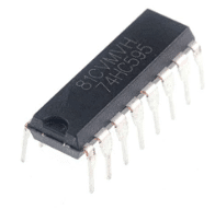
74HC595 Shift Register
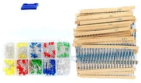
Resistor & LED kit
Makerguides.com is a participant in the Amazon Services LLC Associates Program, an affiliate advertising program designed to provide a means for sites to earn advertising fees by advertising and linking to products on Amazon.com. As an Amazon Associate we earn from qualifying purchases.
Function of the 74HC595 Shift Register
The 74HC595 shift register is an integrated circuit (IC) that converts a stream of serial data into parallel data. This allows you to control many more, additional outputs using just a three pins on your Arduino.
A shift register has three main components: the serial input (SER), the serial clock (SRCLK), and the latch clock (RCLK). The serial input pin is used to input the data bit by bit. While the serial clock pin shifts the data through the registers with every tick of the clock. Finally, the latch clock pin is used to update the outputs with the shifted data.
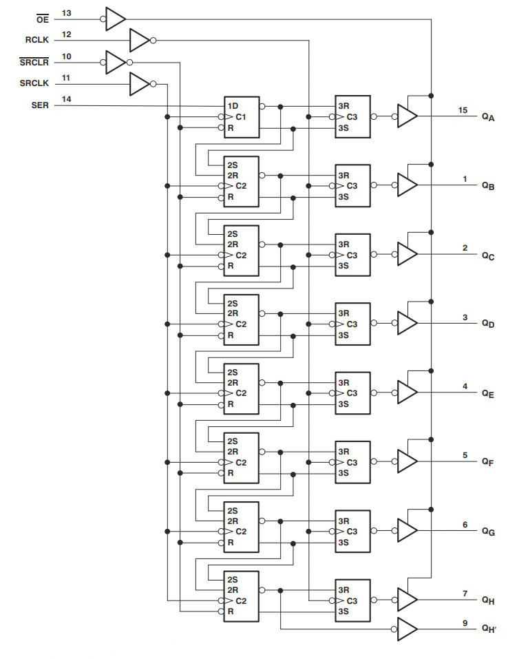
Functional Block Diagram
The image below shows functional block diagram with the 8 internal registers of the 74HC595. You can see the control inputs (OE, RCLL, SRCLR, SRCLK, SER) and the 8 outputs (QA … QH).
Converting Serial Data to Parallel Output
When you send a byte of data to the shift register, it stores the bits in its internal registers. Once all the bits have been shifted in, you can update the outputs by toggling the latch clock pin. This causes the shift register to transfer the stored data to its 8 output pins.
So we are converting a serial stream of bits into a parallel output of 8 bits. Below you can see a beautiful animation from Last Minute ENGINEERS that shows the process. Note the change in the red output bits when the data latch signal goes high.
Controlling the 74HC595
The precise steps needed to control the 74HC595 via the RCLK, SER and SRCLK pins are as follows:
- Set the latch pin (RCLK) to LOW to ensure that the output pins are not updated while shifting the data.
- Send the data bit by bit to the serial data input pin (SER) .
- For each bit, pulse the clock pin (SRCLK) to shift the data into the shift register.
- Repeat steps 2 and 3 until all the bits are shifted into the shift register.
- Once all the bits are shifted, pulse the latch pin (RCLK) to transfer the data from the shift register to the output register.
- The parallel data is now available on the output pins (QA, …, QH) of the 74HC595, which can be connected to external devices such as LEDs, relays, or other digital components.
The image below shows the timing diagram of these steps:
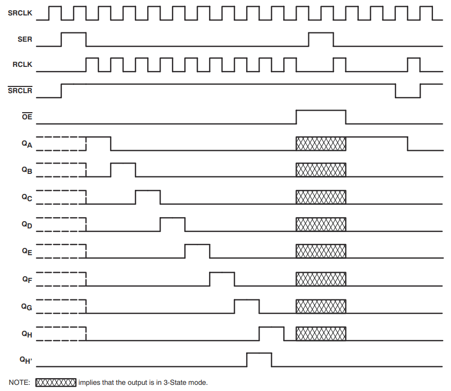
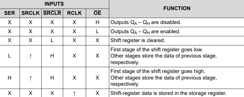
Apart from the RCLK, SER and SRCLK pins, you can use the OE pin to enable or disable the outputs. This comes in handy, if you want to send a PWM signal. We will discuss this in more detail later. The table below lists functional modes of the 74HC595 based on the input control signals.
Specification of the 74HC595
In this section, we have a quick look at the specification of the 74HC595. You can find the complete datasheet with more detailed information here.
Pinout
The picture below shows the Pinout of the 74HC595. Note that in some other datasheets the pins are named differently, e.g. Q0, …, Q7 vs QA, …, QH for the 8 output pins. But the arrangement and function of the pins will be the same.
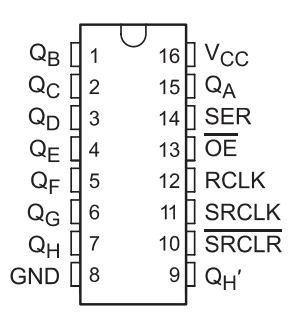
Apart from the output pins, you have ground (GND), the input control pins (RCLK, SER, SRCLK, SRCLR, OE) and the QH’ , which allows you to chain multiple 74HC595s. The following table lists all the pins and their functions.
| Pin | Name | Function |
|---|---|---|
| 1 | QB | Output: B |
| 2 | QC | Output: C |
| 3 | QD | Output: D |
| 4 | QE | Output: E |
| 5 | QF | Output: F |
| 6 | QG | Output: G |
| 7 | QH | Output: H |
| 8 | GND | Ground |
| 9 | QH’ | Output: Chaining |
| 10 | SRCLR | Input: Shift Register Clear |
| 11 | SRCLK | Input: Shift Register Clock |
| 12 | RCLK | Input: Reset Clock, Latch output |
| 13 | OE | Input: Output Enable |
| 14 | SER | Input: Serial, Send serial data |
| 15 | QA | Output: A |
| 16 | VCC | Power (2V…6V) |
Voltages and Currents
The 74HC595 works with a supply voltage (VCC) from 2V to 6V and requires only 80μA to operate. In total the load on the 74HC595 must not draw more than 70mA.
You can operate the 74HC595 with 5V or 3.3V logic (and power supply). So it is easy to use with an ESP8266 or an ESP32 as well.
While the outputs can drive up to 35mA individually, the output voltage starts to drop if you go beyond 6mA. So even driving something low current as some LEDs, will require a current limiting resistor. Typically, you want to pick at least 470Ω or better 560Ω.
Typical Application Schematic
The following picture shows a typical application schematic for the 74HC595. It uses a microcontroller to switch 8 LEDs with current limiting resistors of 560Ω. There is also a small 0.1µF capacitor for noise protection.
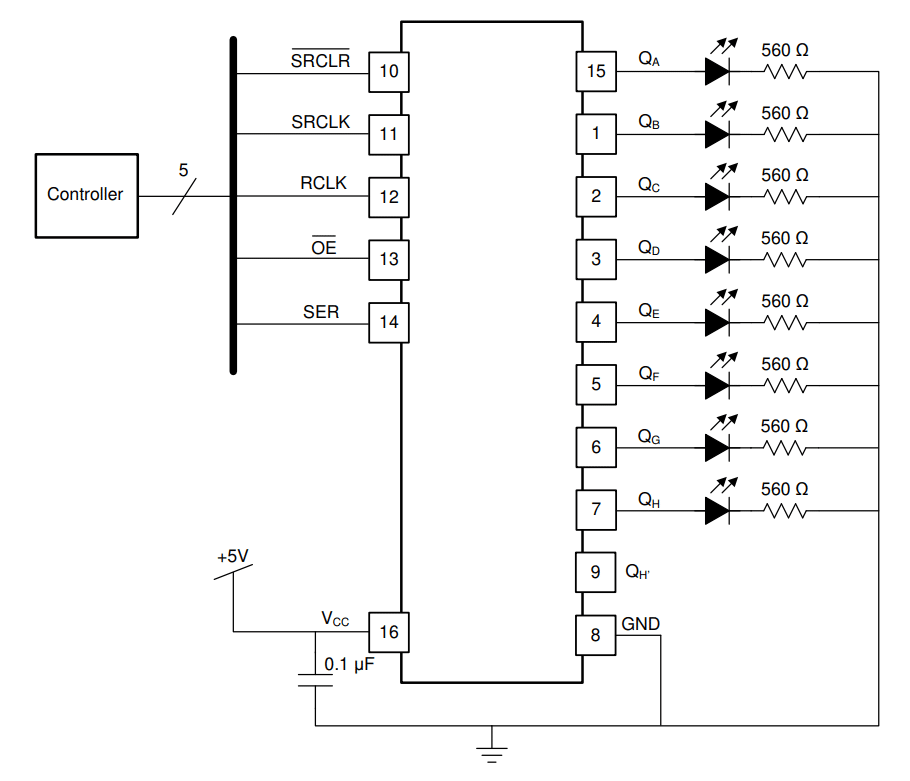
I will show you how to build this circuit with an Arduino in the next section.
Wiring of the 74HC595 Shift Register
The picture below show the complete wiring of the 74HC595 Shift Register with an Arduino to control 8 LEDs. It essentially follows the Typical Application Schematic shown before, with the exception that I am using 470Ω resistors for the LEDs and omit the 0.1µF capacitor. Feel free to add the capacitor if you observe an unstable behavior of the circuit.
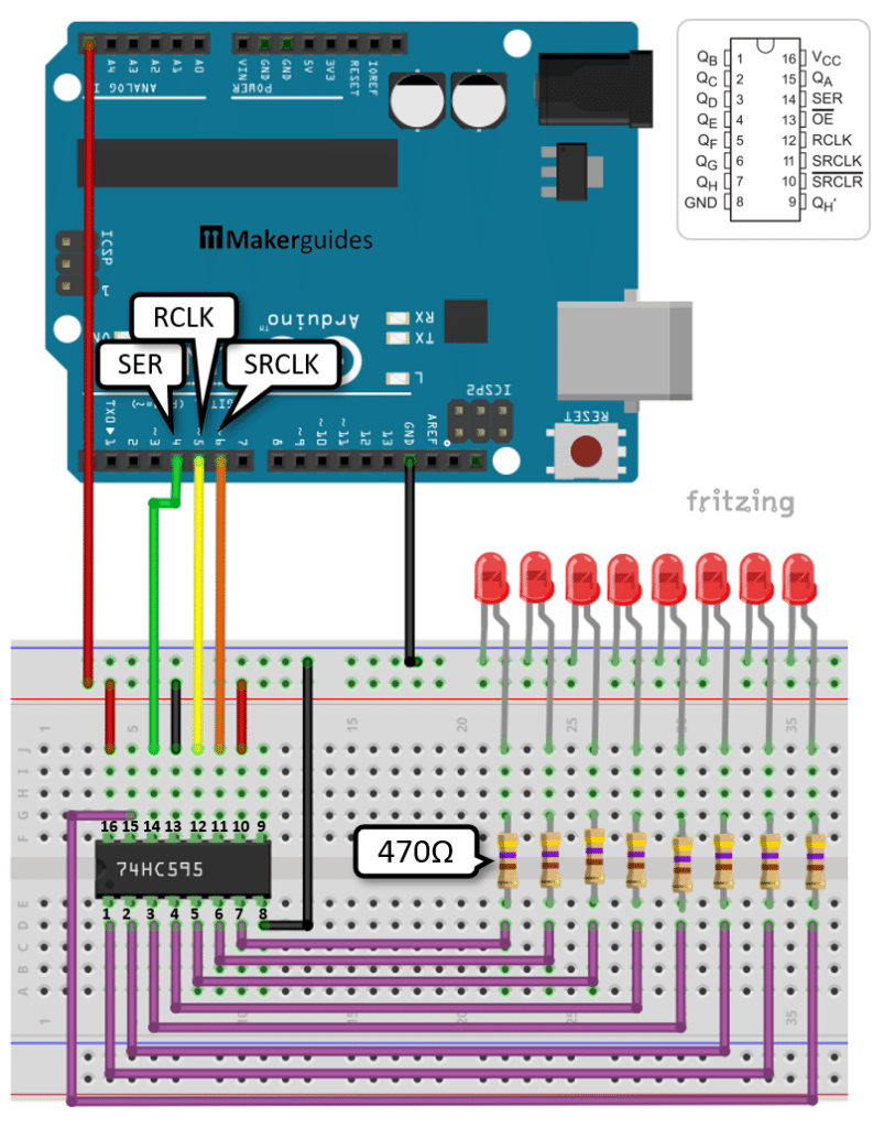
The wiring looks a bit complex but is actually straight forward. Start by connecting the 5V and GND of the Arduino to the positive and negative power rails of the breadboard (red and black wires).
Then add the 8 LEDs and make sure the shorter pin of the LEDs is connected to the negative (blue) power rail. For each LED, insert a 470Ω (or 560Ω) resistor into the breadboard. Make sure that each resistor is connected to the longer pin of the LED and bridges the gap on the breadboard.
Now connect all the resistors to the output pins QA, …, QH of the 74HC595 (purple wires). Watch out for the unusual connection to QA, which is on the opposite side of the IC (pin 15).
Next we connect the positive power to pin 16 (red wire) and ground to pin 8 (black wire) of the 74HC595. What remains now are the control pins. OE, which is on pin 13, is fixed to ground (black wire) and SRCLR on pin 10 is connected to positive power (red wire).
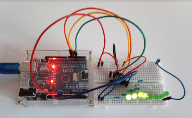
Finally, we connect SER on pin 13 of the 74HC595 to pin 4 of the Arduino (green wire). RCLK on pin 12 gets connected to pin 5 of the Arduino (yellow wire). And SRCLK on pin 11 needs to be connected to pin 6 on the Arduino (orange wire). Below is a picture of the complete circuit on a real breadboard.
And that completes the wiring. In the next section we write some simple code to test the wiring.
Code to Control LEDs using the 74HC595 Shift Register
The following code uses the 74HC595 to light up the 8 connected LEDs in sequence. Have a quick look at the complete code first, before we dive into its details.
// Light up LEDs in sequence using Shift Register
const int dataPin = 4;   // SER
const int latchPin = 5;  // RCLK
const int clockPin = 6;  // SRCLK

void setRegister(byte val) {
  digitalWrite(latchPin, LOW);
  shiftOut(dataPin, clockPin, MSBFIRST, val);
  digitalWrite(latchPin, HIGH);
  delay(1000);
}

void setup() {
  pinMode(latchPin, OUTPUT);
  pinMode(dataPin, OUTPUT);
  pinMode(clockPin, OUTPUT);
}

void loop() {
  byte leds = 0b00000000;
  setRegister(leds);

  for (int i = 0; i < 8; i++) {
    bitSet(leds, i);
    setRegister(leds);
  }
}
Constants and Variables
We start by defining the constants dataPin, latchPin, and clockPin. These pins are connected to the corresponding pins on the shift register. The dataPin is used to send data to the shift register, the latchPin is used to latch the data to the output pins, and the clockPin is used to shift the data in.
const int dataPin = 4;   // SER
const int latchPin = 5;  // RCLK
const int clockPin = 6;  // SRCLK
Register Set function
The setRegister() function is responsible for setting the value of the shift register. It takes a byte value as input, which represents the state of the 8 LEDs connected to the shift register. Inside the function, we first set the latchPin to LOW to prepare for shifting the data. Then, we use the shiftOut() function to send the data to the shift register. Finally, we set the latchPin to HIGH to latch the data and update the outputs. We also add a delay of 1000ms to slow down the sequential lighting up of the LEDs.
void setRegister(byte val) {
  digitalWrite(latchPin, LOW);
  shiftOut(dataPin, clockPin, MSBFIRST, val);
  digitalWrite(latchPin, HIGH);
  delay(1000);
}
Note that you can reverse the order in which the bits of the byte are sent by changing the bitOrder parameter from MSBFIRST (Most Significant Bit FIRST) to LSBFIRST (Least Significant Bit FIRST). The LEDs will then light up in reversed order.
Setup function
In the setup() function, we set the latchPin, dataPin, and clockPin as outputs using the pinMode() function. This is necessary to ensure that these pins can be used for outputting data to the shift register.
void setup() {
  pinMode(latchPin, OUTPUT);
  pinMode(dataPin, OUTPUT);
  pinMode(clockPin, OUTPUT);
}
Loop function
In the loop() function, we first initialize a byte variable leds with the value 0b00000000. This represents the initial state of the LEDs, where all LEDs are turned off. We then call the setRegister() function to set the initial state of the shift register.
Next, we enter a for loop that runs from 0 to 7. In each iteration, we use the bitSet() function to set a specific bit in the leds byte variable, representing the additional LED we want to turn on.
We then call the setRegister() function again to update the state of the shift register and light up the corresponding LED. By repeating this process in the loop, we can sequentially light up all LEDs connected to the shift register. And when the loop starts again, we reset all LEDs to the off state.
void loop() {
  byte leds = 0b00000000;
  setRegister(leds);

  for (int i = 0; i < 8; i++) {
    bitSet(leds, i);
    setRegister(leds);
  }
}
If you build this circuit and run this code you should see the following sequence of lights.
Instead of a set of 8 individual LEDs you could also use an LED Bar. Have a look at our tutorial: LED Bar Graph With Arduino UNO. And if you struggle with the control of LEDs in general, have a read of How To Blink An LED Using Arduino (4 Different Ways) and Control Multiple LEDs With Different Delays with Arduino.
Notes
Note that you can easily send (lighting) patterns as binary numbers to activate the LEDs. Since a byte has 8 bits, we can use a byte to describe the state for each of our 8 LEDs (1 for on, and 0 for off). For instance to, activate every second LED you could use the following binary value 0b10101010 and send it via setRegister.
void loop() {
  setRegister(0b10101010);
}
Or, if you want to send an entire sequence of patterns, that is easily done as well:
byte patterns[] = { 0b00000000,
                    0b10101010,
                    0b11111111 };

void loop() {
  for (int i = 0; i < 3; i++) {
    setRegister(patterns[i]);
  }
}
Instead of hard coding the patterns, you could also create patterns that simulate a bar graph and control them via a potentiometer, see How use Arduino to control an LED with a Potentiometer.
Finally, note that there is a bitClear() function that operates as an opposite to the bitSet() function, which allows you to set bits to zero. With that you can implement a running light and other effects.
void loop() {
  uint8_t leds = 0b00000000;

  for (int i = 0; i < 8; i++) {
    bitSet(leds, i);
    setRegister(leds);
  }

  for (int i = 7; i >=0; i--) {
    bitClear(leds, i);
    setRegister(leds);
  }
}
For more pattern ideas or applications have a look at our Spin the Wheel Game tutorial.
In the code above, we have switched the LEDs fully on or off. While we cannot dim individual LEDs, we can dim all active LEDs by using the OE (output enable) signal. How that is done, is it the topic of the next section.
PWM Signal to Control the 74HC595 Shift Register
The OE (Output Enable) pin of the 74HC595 allows you to enable or disable all output pins QA, …, QH. In the previous circuit we connected OE to ground, which enabled all outputs. Note the line over OE in the pinout that indicates that the pin logic is inverted. Setting OE to low enables the outputs, while setting OE to high disables them.
Instead of completely switching the outputs on and off, we can also send a PWM signal to the OE pin, which allows us to “dim” all outputs. Note that this will always affect all outputs QA, …, QH , so we cannot “dim” individual LEDs.
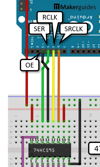
Wiring
The following picture shows the changed wiring. Instead of connecting the OE pin of the 74HC595 to ground (black wire), we need to connected to a PWM pin of the Arduino. In this case, I pick pin ~3. All other wires remain the same.
Code
In the code we can now use pin 3 of the Arduino to send a PWM signal to the OE pin of the 74HC595 to dim all of its outputs. Below is a code example that essentially does the same as the one above but at a the end of the cycle dims all LEDs from full brightness to 0, before starting the cycle again.
int dataPin = 4;    // SER
int latchPin = 5;   // RCLK
int clockPin = 6;   // SRCLK
int enablePin = 3;  // OE

void setRegister(uint8_t val) {
  digitalWrite(latchPin, LOW);
  shiftOut(dataPin, clockPin, MSBFIRST, val);  // LSBFIRST
  digitalWrite(latchPin, HIGH);
  delay(100);
}

void setBrightness(byte brightness) {
  analogWrite(enablePin, 255 - brightness);
}

void setup() {
  pinMode(latchPin, OUTPUT);
  pinMode(dataPin, OUTPUT);
  pinMode(clockPin, OUTPUT);
  pinMode(enablePin, OUTPUT);
}

void loop() {
  uint8_t leds = 0b00000000;
  setRegister(leds);

  setBrightness(255);
  for (int i = 0; i < 8; i++) {
    bitSet(leds, i);
    setRegister(leds);
  }

  for (byte b = 255; b > 0; b--) {
    setBrightness(b);
    delay(2);
  }
}
The only new bit is the setBrightness() function that writes the PWM to the enablePin using the analogWrite() function. Usually full brightness of the LEDs would be achieved for a value of 255. But since the logic of the OE pin is inverted, we need to subtract the desired brightness from 255, to compensate for the inversion.
We use the setBrightness() function in the second loop to turn down the brightness b from 255 to 0 with a very short delay of 2msec.
  for (byte b = 255; b > 0; b--) {
    setBrightness(b);
    delay(2);
  }
If you upload this code to your Arduino and run it, you will see the following effect. The LEDs light up in sequence and when all LEDs are lit, they slowly dim down to zero and the cycle starts again.
In the next section we discuss how to create more than 8 outputs by chaining multiple 74HC595s.
Chaining of 74HC595 Shift Registers
A single 74HC595 has 8 outputs QA, …, QH and needs three control wires. The good news is, you can chain multiple 74HC595 Shift Resistors to add as many outputs as you like (in reasonable limits) and still using only three control wires.
Chaining 74HC595s if very simple. For instance, if you want to chain two 74HC595s, just connect the QH‘ pin of the first 74HC595 to the SER pin of the second. See the picture below.
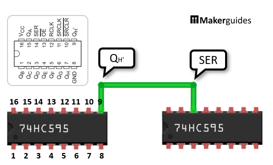
Wiring
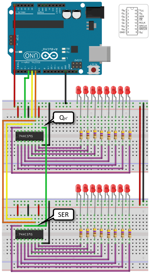
All other connections remain the same and are duplicated for the second 74HC595. The image below show the complete wiring of two chained 74HC595 that allow you to control 16 LEDs.
Code
To control the 16 LEDs you can use the following code. As before it lights up all LEDs in sequence, resets them to zero and then restarts the cycle.
// Light up 16 LEDs in sequence using two Shift Registers
const int dataPin = 4;   // SER
const int latchPin = 5;  // RCLK
const int clockPin = 6;  // SRCLK

const int nRegister = 2;
const int nOutput = nRegister * 8;

void setRegister(byte vals[]) {
  digitalWrite(latchPin, LOW);
  for (int i = nOutput - 1; i >= 0; i--) {
    digitalWrite(clockPin, LOW);
    digitalWrite(dataPin, vals[i]);
    digitalWrite(clockPin, HIGH);
  }
  digitalWrite(latchPin, HIGH);
  delay(100);
}

void setup() {
  pinMode(latchPin, OUTPUT);
  pinMode(dataPin, OUTPUT);
  pinMode(clockPin, OUTPUT);
}

void loop() {
  byte leds[nOutput];

  for (int i = 0; i < nOutput; i++) {
    leds[i] = HIGH;
    setRegister(leds);
  }

  for (int i = 0; i < nOutput; i++) {
    leds[i] = LOW;
  }
  setRegister(leds);
}
Instead of setting the bits of a byte that represents the state of 8 LEDs, we use a byte array leds[] here. It stores the states of all 16 LEDs individually. That wastes some memory but it is a bit easier to use and will work for an arbitrary number chained shift registers. Just set the nRegister constant to the number of registers you connect.
As a consequence of this flexibility we have to change the setRegister() function a bit. It now takes a byte array and we write the values in the array iteratively to the dataPin. Note that the loop runs in reversed order, to mimic the MSBFIRST order we used in the other code.
void setRegister(byte vals[]) {
  digitalWrite(latchPin, LOW);
  for (int i = nOutput - 1; i >= 0; i--) {
    digitalWrite(clockPin, LOW);
    digitalWrite(dataPin, vals[i]);
    digitalWrite(clockPin, HIGH);
  }
  digitalWrite(latchPin, HIGH);
  delay(100);
}
Finally, we set the state in the leds[] array iteratively and set it to HIGH or LOW, depending if we want the LED on or off. The first loop switches on all LEDs one by one, while the second loop switches them all off at once. Note that setRegister is called within the first loop but after the second loop.
  for (int i = 0; i < nOutput; i++) {
    leds[i] = HIGH;
    setRegister(leds);
  }

  for (int i = 0; i < nOutput; i++) {
    leds[i] = LOW;
  }
  setRegister(leds);
And that’s it. Now you know pretty much everything you need to know about the 74HC595 Shift Register and can use it to add outputs to your Arduino.
Summary
In this blog post, we have learned how to expand the number of outputs on an Arduino board by using a 74HC595 shift register. By utilizing this shift register, we can significantly increase the number of devices or components that can be controlled by the Arduino.
We started by discussing the required parts for this project, which include an Arduino board, a 74HC595 shift register, resistors, LEDs, and jumper wires.
Next, we explored the function of the 74HC595 shift register. This integrated circuit allows us to convert a serial input signal into a parallel output signal, effectively multiplying the number of outputs available. It works by shifting the bits of data through its internal registers.
We then moved on to the wiring of the 74HC595 shift register. We provided a detailed circuit diagram and explained how to connect the shift register to the Arduino board, LEDs, and resistors.
After the wiring was complete, we implemented the code required to control the 74HC595 shift register. We provided an example code snippet that demonstrates how to shift data into the shift register and control the output pins accordingly. The code is explained step by step, making it easy to understand and modify for your specific needs.
Furthermore, we explored how to use pulse width modulation (PWM) signals to control the 74HC595 shift register. PWM allows us to control the brightness of LEDs connected to the shift register’s output pins. We provided an example code snippet and explained how to adjust the PWM signal to achieve the desired effect.
Additionally, we discussed the possibility of chaining multiple 74HC595 shift registers together to further expand the number of outputs.
If you have any further questions, please refer to the Frequently Asked Questions section below or leave a comment.
And now have fun 😉
Frequently Asked Questions
Here are some frequently asked questions about using the 74HC595 Shift Register to add more outputs to your Arduino:
Q: What is a shift register?
A: A shift register is a digital circuit that can store and shift data. It is commonly used to expand the number of outputs on a microcontroller like Arduino. The 74HC595 is a popular shift register IC that can control up to 8 outputs using only 3 pins from the Arduino.
Q: How does the 74HC595 shift register work?
A: The 74HC595 shift register works by using a serial input to load data into its internal storage registers. The data can then be shifted out to the output pins one bit at a time. By cascading multiple shift registers, you can control even more outputs using the same number of Arduino pins.
Q: What are the advantages of using a shift register?
A: Using a shift register like the 74HC595 has several advantages. Firstly, it allows you to control multiple outputs using only a few Arduino pins, which is especially useful when you have limited pins available. Secondly, it reduces the amount of wiring required, making your project more organized and easier to manage. Lastly, it frees up Arduino pins for other purposes, enabling you to add more functionality to your project.
Q: Can I control the brightness of LEDs using the 74HC595 shift register?
A: Yes, you can control the brightness of LEDs using the 74HC595 shift register. By using Pulse Width Modulation (PWM), you can vary the duty cycle of the output pins connected to the LEDs. This allows you to control the brightness levels of the LEDs, creating effects like fading or pulsing.
Q: Can I chain multiple 74HC595 shift registers together?
A: Yes, you can chain multiple 74HC595 shift registers together to control even more outputs. By connecting the serial output (Q7′) of one shift register to the serial input (SER) of the next shift register, you can create a daisy-chain configuration. This allows you to control a large number of outputs using a minimal number of Arduino pins.
Q: Are there any limitations to using the 74HC595 shift register?
A: While the 74HC595 shift register is a versatile and useful component, it does have some limitations. Firstly, it can only control digital outputs, so it is not suitable for controlling analog devices directly. Secondly, it has a limited current sourcing capability, so if you need to drive high-current devices like motors or relays, you will need additional circuitry. Lastly, the shift register requires some setup and configuration, so it may not be suitable for very simple projects where simplicity is a priority.
Q: Can I use the 74HC595 shift register with other microcontrollers besides Arduino?
A: Yes, the 74HC595 shift register can be used with other microcontrollers besides Arduino. As long as the microcontroller can communicate using digital signals and has the necessary pins available, you can use the shift register to expand the number of outputs.
Q: How do I connect the 74HC595 shift register to my Arduino?
A: To connect the 74HC595 shift register to your Arduino, you will need to connect the following pins: SER (serial input) to an Arduino digital pin, SRCLK (shift register clock) to another digital pin, RCLK (register clock) to a third digital pin, and OE (output enable) to ground. Additionally, you will need to connect the QH’ (serial output) of one shift register to the SER (serial input) of the next shift register if you are chaining multiple shift registers together.
Q: Can I use the 74HC595 shift register to read inputs as well?
A: No, the 74HC595 shift register is designed for output control only. It does not have the capability to read inputs. If you need to read inputs, you will need to use a different component, such as a shift register with input capabilities or a different type of microcontroller pin.
Q: Can I use the 74HC595 shift register with other types of digital components besides LEDs?
A: Yes, you can use the 74HC595 shift register with other types of digital components besides LEDs. The shift register can control any digital component that requires a digital signal to turn on or off, such as transistors, relays, or other integrated circuits.
Q: Can I use the 74HC595 shift register with other shift register ICs?
A: Yes, you can use the 74HC595 shift register with other shift register ICs as long as they have compatible pin configurations and voltage requirements. However, it is important to note that different shift register ICs may have different features and capabilities, so you will need to consult the datasheets and adjust your code accordingly.
Q: Can I use the 74HC595 shift register with other programming languages besides Arduino IDE?
A: Yes, you can use the 74HC595 shift register with other programming languages besides Arduino IDE. The shift register is a hardware component that can be controlled using any programming language that can communicate with the microcontroller. However, you will need to adapt your code to the specific syntax and libraries of the programming language you are using.
Q: Can I use the 74HC595 shift register with other microcontrollers that operate at different voltages?
A: Yes, you can use the 74HC595 shift register with other microcontrollers that operate at different voltages. However, you will need to ensure that the voltage levels are compatible. If the microcontroller operates at a higher voltage than the shift register, you may need to use level shifters or voltage dividers to ensure proper communication between the two.
Q: How many shift registers can I chain together?
A: The number of shift registers you can chain together depends on several factors, including the available pins on your microcontroller and the desired functionality of your project. In theory, you can chain an unlimited number of shift registers together. However, as you chain more shift registers, the complexity of the circuit and the time required for shifting data may increase. It is recommended to test and validate your circuit design to ensure reliable operation.
Q: Can I use the 74HC595 shift register with other types of shift registers, such as the 74HC164?
A: Yes, you can use the 74HC595 shift register with other types of shift registers, such as the 74HC164. However, it is important to note that different shift registers may have different pin configurations and functionalities. You will need to consult the datasheets of both shift registers and adjust your circuit connections and code accordingly.
Q: Can I use the 74HC595 shift register to control other types of digital displays, like 7-segment displays or LCDs?
A: Yes, you can use the 74HC595 shift register to control other types of digital displays, like 7-segment displays or LCDs. However, you will need additional circuitry and code to interface with these displays. For example, you may need to use multiplexing techniques for 7-segment displays or use a dedicated LCD library for controlling LCDs.
Q: Can I use the 74HC595 shift register to control servos or stepper motors?
A: No, the 74HC595 shift register is not suitable for directly controlling servos or stepper motors. These devices require precise timing and often have specific control signals. Instead, you will need to use dedicated motor driver modules or servo controllers that are designed to handle the specific requirements of these devices.
Q: Can I use the 74HC595 shift register in battery-powered projects?
A: Yes, you can use the 74HC595 shift register in battery-powered projects. The shift register itself consumes very little power, so it should not significantly impact the battery life of your project. However, it is important to consider the power consumption of the components connected to the shift register, such as LEDs or other digital devices, as they may have a greater impact on battery life.
These are some of the frequently asked questions about using the 74HC595 shift register to add more outputs to your Arduino. If you have any other questions, feel free to ask in the comments section below.

I am Puneeth. I love tinkering with open-source projects, Arduino, ESP32, Pi and more. I have worked with many different Arduino boards and currently I am exploring, Arduino powered LoRa, Power line communication and IoT.