In this tutorial, you will learn how to use an IR remote and receiver with the Arduino. I have included wiring diagrams and several example codes to help you get started.
By following the instructions in this tutorial you will be able to use virtually any IR remote (like the one from your TV) to control things connected to the Arduino.
In the code examples below, we will be using the IRremote Arduino library . This library is fairly easy to use and supports many different IR communication protocols. With the first two examples, you can identify the IR protocol of your remote and determine which code it sends when you press on a key/button. Next, I will show you how to map the received code to the key values and display these in the Serial Monitor or on an LCD. Lastly, we will look at controlling the outputs of the Arduino with an IR remote and receiver.
Supplies
Hardware components
Software
Makerguides.com is a participant in the Amazon Services LLC Associates Program, an affiliate advertising program designed to provide a means for sites to earn advertising fees by advertising and linking to products on Amazon.com. As an Amazon Associate we earn from qualifying purchases.
How does an infrared (IR) remote and receiver work?
An IR remote and receiver communicate with each other by transmitting and decoding a signal in the form of pulsed IR radiation.
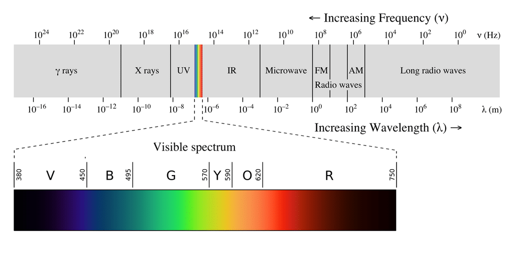
Infrared radiation (IR), or infrared light, is a type of electromagnetic radiation with wavelengths ranging from 700 nm to 1 mm. Because humans can only see light with wavelengths of roughly 400 (violet) to 700 (red) nanometers, IR radiation is invisible to the human eye.
Since IR transmission is a wireless protocol based on a type of light, it requires a clear line of sight between the transmitter (the remote) and the receiver. This means it can’t transmit through walls or ceilings, unlike WiFi or Bluetooth.
IR communication basics
Unfortunately, the IR LED in your remote is not the only source of IR radiation. Any object that has a temperature also radiates in the infrared spectrum. This phenomenon is also used by thermal cameras to detect heat.
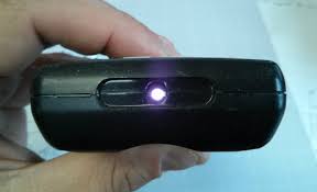
All this ambient IR can interfere with the communication between the remote and the receiver. So how does the receiver only detect the IR signal coming from the remote? The answer is signal modulation.
With signal modulation, the IR light source at the end of the remote is blinked with a specific frequency. In consumer electronics, this carrier frequency is usually around 38 kHz.
This specific frequency is used for commercial IR transmission because it is rare in nature and, therefore, it can be distinguished from the ambient IR.
The receiver is built in such a way that it only lets IR through that is coming in at 38 kHz. This is achieved using a bandpass filter and amplifier. The demodulated binary signal is then sent to the microcontroller (the Arduino) where it is decoded.
IR signal protocol
So what does an IR signal actually look like?
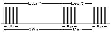
In the image above, the vertical axis can be seen as the voltage going to the IR LED in the remote and the horizontal axis is time. So when the IR LED is on, it is blinked (modulated) at 38 kHz and when it is off, no voltage is applied.
What is important is the amount of time that the IR LED is held high or low (on or off). In the NEC protocol, which is one of the most popular IR transmission protocols, the bits (“1” or “0”) are represented as follows:
Each bit consists of a 560 µs long 38 kHz carrier burst (about 21 cycles) followed by a pause. A logical “1” has a total transmission time of 2.25ms, while a logical “0” only 1.125 ms.
The amount of time the signal stays high or low and the number of bits that are sent for each command is different for all of the IR protocols. In the NEC protocol, the total message usually consists of four 8-bit bytes.
Types of IR receivers
IR receivers, sometimes called IR sensors or IR detection diodes, usually come in two different form factors. You can either buy the diodes separately or mounted on a small breakout board.
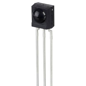
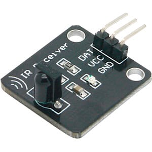
They work exactly the same, so it doesn’t matter which one you use. The only difference is that the breakout board often contains a small LED that blinks every time the receiver detects a signal which can be handy for debugging.
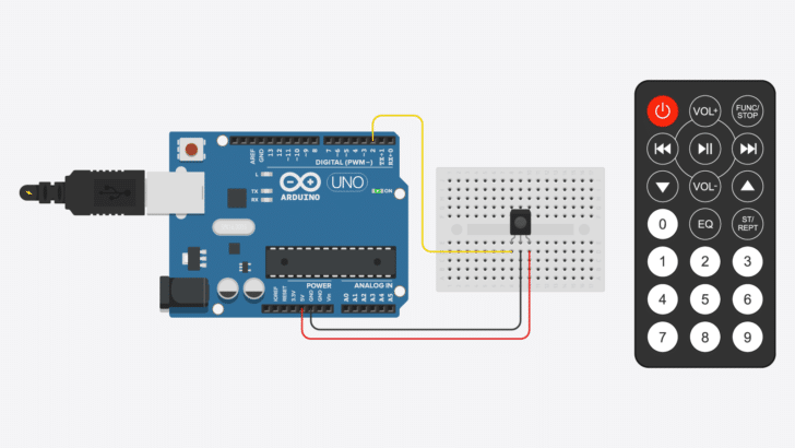
Connecting an IR receiver to the Arduino
It is very easy to hook up an IR receiver to the Arduino as you only need to connect three wires. The output wire can be connected to any of the digital pins of the Arduino. In this case, I connected it to pin 2 for the first examples below.
The supply power pin is connected to 5 V and the middle ground pin to GND. If you are using a receiver that is mounted on a breakout board, check the labels on the PCB as the order of the pins can be different!
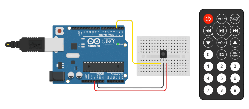
The connections are also given in the table below
IR receiver connections
| IR receiver | Arduino |
|---|---|
| OUT (left) | Pin 2 |
| GND (middle) | GND (-) |
| Vcc (right) | 5 V (+) |
Installing the IRremote Arduino library
For this tutorial, we will be using the popular IRremote library. This library is fairly easy to use and supports many different types of IR remotes.
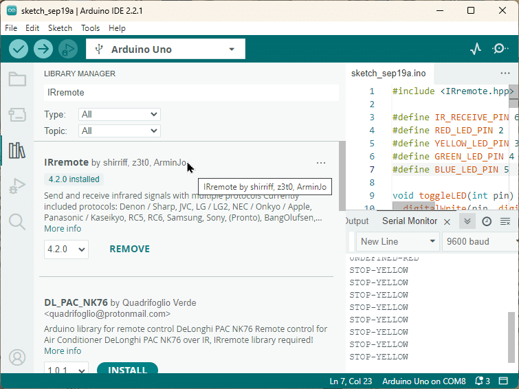
To install the library, go to Tools > Manage Libraries (Ctrl + Shift + I on Windows) in the Arduino IDE. The Library Manager will open and update the list of installed libraries.
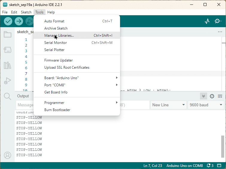
You can search for ‘IRremote’ and look for the library by shirriff and z3to. Select the latest version and then click Install.
Determine the IR protocol used by your remote
NEC is probably the best known and most widespread IR transmission protocol as it is used by the vast majority of Japanese-manufactured consumer electronics. However, many other types of protocols exist. It can be useful to known what type of IR protocol your remote is using if you want to work on more advanced projects. Or you might just be curious
As of Sep 2023, the IRremote library supports the following IR protocols:
- PulseWidth
- PulseDistance
- Apple
- Denon
- JVC
- LG
- LG2
- NEC
- NEC2
- Onkyo
- Panasonic
- Kaseikyo
- Kaseikyo Denon
- Kaseikyo Sharp
- Kaseikyo JVC
- Kaseikyo Mitsubishi
- RC5
- RC6
- Samsung
- Samsung48
- SamsungLG
- Sharp
- Sony
- Bang&Olufsen
- BoseWave
- Lego
- MagiQuest
- Whynter
- FAST
With the short code below you can identify which protocol your remote is using. You can also try some other remotes that you have in your house and see if it can detect the protocol.
IR remote protocol finder
#include "IRremote.hpp"

#define IR_RECEIVE_PIN 2

void setup() {
  Serial.begin(9600);
  IrReceiver.begin(IR_RECEIVE_PIN, ENABLE_LED_FEEDBACK);
}

void loop() {
  if (IrReceiver.decode()) {
    IrReceiver.printIRResultShort(&Serial);
    IrReceiver.resume();
  }
}
I experimented with three of the remotes in my house and two were detected as NEC, while the third one (for an air-conditioning unit) was UNKNOWN:
However, there is an excellent library called IRremoteESP8266, which specifically supports the protocols for various air-conditioners. So, if you want to control your air-conditioning unit vi IR, that’s the place to go but that is not the library we are using here.
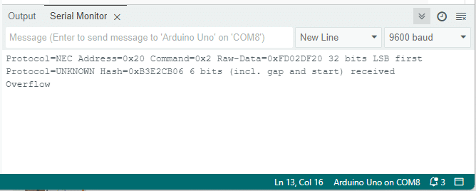
Note: for remotes with unknown protocols you will also see the “Overflow” error in addition to the protocol info. That is simply because the end of the IR command could not be detected, since the protocol was unknown.
Finding the key codes for your remote
Because there are many different types of remotes on the market (with different number of keys and key functions), we need to determine which received signal corresponds to which key.
The IRremote library will read the signal and returns all information about the signal in the following structure:
struct IRData {
    decode_type_t protocol;          // UNKNOWN, NEC, SONY, RC5, PULSE_DISTANCE, ...
    uint16_t address;                // Decoded address
    uint16_t command;                // Decoded command
    uint16_t extra;
    uint16_t numberOfBits;           // Number of bits received for data
    uint8_t flags;                   // IRDATA_FLAGS_IS_REPEAT, IRDATA_FLAGS_WAS_OVERFLOW
    IRRawDataType decodedRawData;    // Up to 32  bit decoded raw data,
    uint32_t decodedRawDataArray[RAW_DATA_ARRAY_SIZE]; // 32 bit decoded raw data for send function.
    irparams_struct *rawDataPtr;     // Pointer of the raw timing data to be decoded.
};
We are especially interested in the command part of that structure. This will contain the code the remote sends depending on which key is pressed. By printing the command value in the Serial Monitor, we can create a conversion table.
The code below does just that. Note that we are adding a delay of 100ms, so that we slow down the printing if a key is pressed continuously, which will result in a repeated print out.
#include "IRremote.hpp"

#define IR_RECEIVE_PIN 2

void setup() {
  Serial.begin(9600);
  IrReceiver.begin(IR_RECEIVE_PIN, ENABLE_LED_FEEDBACK);
}

void loop() {
  if (IrReceiver.decode()) {
    uint16_t command = IrReceiver.decodedIRData.command;
    Serial.println(command);
    delay(100);  // wait a bit
    IrReceiver.resume();
  }
}
After you have uploaded the code, open the Serial Monitor. Now press each key on the remote and record the corresponding value that you see in the Serial Monitor.
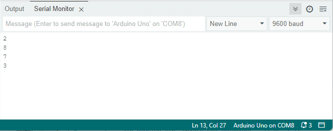
For my remote that controls an audio player, I got the following codes:
| Key | Code |
|---|---|
| Play | 7 |
| Stop | 3 |
| Mute | 20 |
| Next track | 8 |
| Previous track | 2 |
| Volume up | 31 |
| Volume down | 23 |
Your table will probably look different! You will have to create your own to use the code examples below.
Print key names in the Serial Monitor
Now that we know which code corresponds to which keypress, we can modify the code to print the name of the pressed key in the Serial Monitor.
For this, we will be using a switch case control structure. This lets us execute a different piece of code depending on which key is pressed.
The code example below prints the key name in the Serial Monitor instead of the integer value like we did in the previous example. Note that we keep the delay, so that we don’t overwhelm the receiver with repeated signals when a key is pressed continuously.
#include "IRremote.hpp"

#define IR_RECEIVE_PIN 2

void setup() {
  Serial.begin(9600);
  IrReceiver.begin(IR_RECEIVE_PIN, ENABLE_LED_FEEDBACK);
}

void loop() {
  if (IrReceiver.decode()) {
    uint16_t command = IrReceiver.decodedIRData.command;
    switch (command) {
      case 7:
        Serial.println("PLAY");
        break;
      case 3:
        Serial.println("STOP");
        break;
      case 20:
        Serial.println("MUTE");
        break;
      case 8:
        Serial.println("NEXT");
        break;
      case 2:
        Serial.println("PREV");
        break;
      case 31:
        Serial.println("VOL+");
        break;
      case 23:
        Serial.println("VOL-");
        break;
      default:
        Serial.println("UNDEFINED");
    }

    delay(100);
    IrReceiver.resume();
  }
}
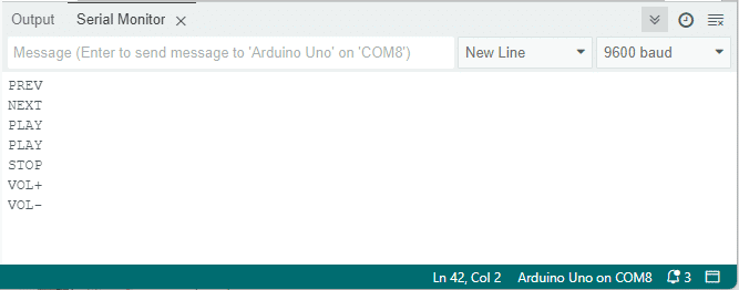
Here is what I see on the Serial Monitor when pressing some keys on my remote:
If your remote has different keys and sends different codes than the ones shown in the table above, simply replace the value and name of the lines in the switch case statement that looks like this:
 case 31:
   Serial.println("VOL+");
These lines translate to: when the command value is equal to 31, print “VOL+” in the Serial Monitor. If there is no case statement for a command value the default clause is activated and “UNDEFINED” is printed.
How the code works
The first line of the code includes the IRremote.hpp library. This library provides the functions necessary to interact with IR signals.
#include "IRremote.hpp"
Next, we define the pin that will receive the IR signals. In this case, we’re using pin 2.
#define IR_RECEIVE_PIN 2
In the setup() function, we start serial communication at a baud rate of 9600. We also initiate the IR receiver on the pin we defined earlier, with LED feedback enabled. That means whenever a code is received an LED on the Arduino (and the IR receiver module) will flicker, which is handy for debugging.
void setup() {
  Serial.begin(9600);
  IrReceiver.begin(IR_RECEIVE_PIN, ENABLE_LED_FEEDBACK);
}
In the loop() function, we check if the IR receiver has decoded a signal. If it has, we get the command value from the decoded data.
void loop() {
  if (IrReceiver.decode()) {
    uint16_t command = IrReceiver.decodedIRData.command;
We then use a switch statement to interpret the command. Each case corresponds to a different command sent from the remote. For example, if the command is 7, the Arduino prints “PLAY” to the serial monitor.
    switch (command) {
      case 7:
        Serial.println("PLAY");
        break;
      case 3:
        Serial.println("STOP");
        break;
        ...

      case 23:
        Serial.println("VOL-");
        break;
      default:
        Serial.println("UNDEFINED");
    }
After interpreting the command, we delay for 100 milliseconds and then resume the IR receiver. This allows it to decode the next signal.
    delay(100);
    IrReceiver.resume();
  }
}
This code provides a basic framework for reading and interpreting signals from an IR remote. You can modify it to suit your specific needs.
IR remote and receiver with Arduino and LCD example
The following example can be used to print the pressed key values on a character LCD. I have written a detailed tutorial on using character LCD displays which you can find here:
If you prefer to use an I2C LCD that needs fewer connections, see the tutorial below:
For this example, I connected the output of the IR receiver to digital pin 8 instead of 2. The connections for the character LCD display are shown in the wiring diagram below. Note that you also need a 10 kΩ potentiometer to set the contrast of the display and a 220 Ω resistor to control the brightness of the backlight.
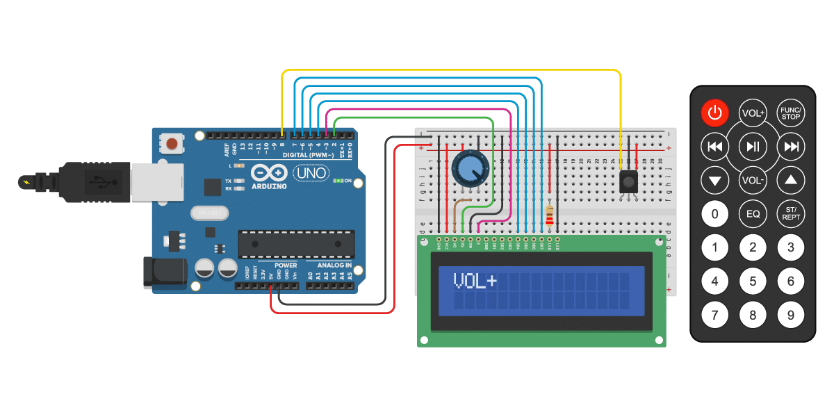
The connections are also given in the table below. The leftmost pin of the LCD is pin 1 (GND).
LCD and IR receiver connections
| Pin | Connection |
|---|---|
| LCD pin 1 (GND) | Arduino GND |
| LCD pin 2 (VCC) | Arduino 5 V |
| LCD pin 3 (VO) | Middle pin potentiometer |
| Left pin potentiometer | Arduino 5 V |
| Right pin potentiometer | Arduino GND |
| LCD pin 4 (RS) | Arduino pin 2 |
| LCD pin 5 (RW) | Arduino GND |
| LCD pin 6 (E) | Arduino pin 3 |
| LCD pin 11 (DB4) | Arduino pin 4 |
| LCD pin 12 (DB5) | Arduino pin 5 |
| LCD pin 13 (DB6) | Arduino pin 6 |
| LCD pin 14 (DB7) | Arduino pin 7 |
| LCD pin 15 (LED-anode) | Arduino 5 V via 220Ω resistor |
| LCD pin 16 (LED-kathode) | Arduino GND |
| IR receiver OUT (left) | Arduino pin 8 |
| IR receiver GND (middle) | Arduino GND |
| IR receiver Vcc (right) | Arduino 5 V |
If you encounter any problems with the LCD display, see this tutorial for more details.
With the example code below, you can print the pressed key on the LCD.Again, if your remote sends different codes, just replace the command values and corresponding key values in the switch case statement.
IR remote and receiver with Arduino and LCD display example code
You can copy the code by clicking on the button in the top right corner of the code field.
#include "IRremote.hpp"
#include "LiquidCrystal.h"

// LCD object with pin parameters (RS, E, D4, D5, D6, D7)
LiquidCrystal lcd = LiquidCrystal(2, 3, 4, 5, 6, 7);

#define IR_RECEIVE_PIN 8

void setup() {
  lcd.begin(16, 2);  // LCD with 16 columns and 2 rows
  IrReceiver.begin(IR_RECEIVE_PIN, ENABLE_LED_FEEDBACK);
}

void loop() {
  if (IrReceiver.decode()) {
    uint16_t command = IrReceiver.decodedIRData.command;
    switch (command) {
      case 7:
        lcd.print("PLAY");
        break;
      case 3:
        lcd.print("STOP");
        break;
      case 20:
        lcd.print("MUTE");
        break;
      case 8:
        lcd.print("NEXT");
        break;
      case 2:
        lcd.print("PREV");
        break;
      case 31:
        lcd.print("VOL+");
        break;
      case 23:
        lcd.print("VOL-");
        break;
      default:
        lcd.print("UNDEFINED");
    }

    delay(100);
    IrReceiver.resume();
  }
}
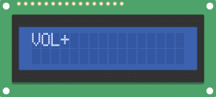
You should see the following output on the LCD if you press the VOL+ key. Note that you might have to adjust the potentiometer to increase the contrast of the display.
Control LEDs (Arduino outputs) with IR remote and receiver
Although it’s fun to see the key values in the Serial Monitor or on an LCD display, you will probably want to use the remote for something more useful, i.e. actual control something. In the following example, I will show you how to toggle LEDs on and off with the remote. You can also use this type of code to control relays, lights, and motors.
The code looks mostly the same as the previous examples but I added extra functionality to control the LEDs.
You will have to create the following circuit to control the LEDs:
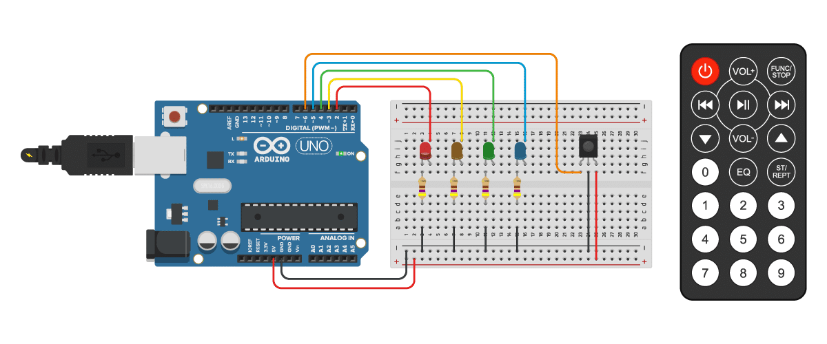
The LEDs are connected to pins 2 to 5 of the Arduino and the output of the IR receiver to pin 6. I used some 470 Ω resistors to limit the current going through the LEDs. The usual operating current of 3 and 5 mm LEDs is around 20 mA. You can determine what value resistor you need with an online calculator like this one. I like to buy these resistor assortments on Amazon so I always have the right value on hand.
#include "IRremote.hpp"

#define IR_RECEIVE_PIN 6
#define RED_LED_PIN 2
#define YELLOW_LED_PIN 3
#define GREEN_LED_PIN 4
#define BLUE_LED_PIN 5

void toggleLED(int pin) {
  digitalWrite(pin, digitalRead(pin) == HIGH ? LOW : HIGH);
}

void setup() {
  Serial.begin(9600);

  IrReceiver.begin(IR_RECEIVE_PIN, ENABLE_LED_FEEDBACK);

  pinMode(RED_LED_PIN, OUTPUT);
  pinMode(YELLOW_LED_PIN, OUTPUT);
  pinMode(GREEN_LED_PIN, OUTPUT);
  pinMode(BLUE_LED_PIN, OUTPUT);

  digitalWrite(RED_LED_PIN, LOW);
  digitalWrite(YELLOW_LED_PIN, LOW);
  digitalWrite(GREEN_LED_PIN, LOW);
  digitalWrite(BLUE_LED_PIN, LOW);
}

void loop() {
  if (IrReceiver.decode()) {
    uint16_t command = IrReceiver.decodedIRData.command;
    switch (command) {
      case 7:
        Serial.println("PLAY-BLUE");
        toggleLED(BLUE_LED_PIN);
        break;
      case 3:
        Serial.println("STOP-YELLOW");
        toggleLED(YELLOW_LED_PIN);
        break;
      case 20:
        Serial.println("MUTE-GREEN");
        toggleLED(GREEN_LED_PIN);
        break;
       default:
        Serial.println("UNDEFINED-RED");
        toggleLED(RED_LED_PIN);
    }

    delay(100);
    IrReceiver.resume();
  }
}
Code explanation
First, we again include the IRremote.hpp library, which provides functions for working with IR remotes.
#include "IRremote.hpp"
Next, we define the pin numbers for the IR receiver and the LED pins. Note that we use a different pin (PIN 6) for the receiver than before (PIN 2).
#define IR_RECEIVE_PIN 6
#define RED_LED_PIN 2
#define YELLOW_LED_PIN 3
#define GREEN_LED_PIN 4
#define BLUE_LED_PIN 5
Then, we define a function called toggleLED that toggles the state of an LED pin. It takes an int parameter pin, which represents the pin number of the LED. If the pin is HIGH we set it to LOW and vice versa.
void toggleLED(int pin) {
  digitalWrite(pin, digitalRead(pin) == HIGH ? LOW : HIGH);
}
In the setup function, we initialize the serial communication at a baud rate of 9600. We also initialize the IR receiver and set the LED pins as output. Finally, we turn off all the LEDs.
void setup() {
  Serial.begin(9600);

  IrReceiver.begin(IR_RECEIVE_PIN, ENABLE_LED_FEEDBACK);

  pinMode(RED_LED_PIN, OUTPUT); // set the LED pins as output
  pinMode(YELLOW_LED_PIN, OUTPUT);
  pinMode(GREEN_LED_PIN, OUTPUT);
  pinMode(BLUE_LED_PIN, OUTPUT);

  digitalWrite(RED_LED_PIN, LOW); // turn all the LEDs off
  digitalWrite(YELLOW_LED_PIN, LOW);
  digitalWrite(GREEN_LED_PIN, LOW);
  digitalWrite(BLUE_LED_PIN, LOW);
}
In the loop function, we check if the IR receiver has received a signal. If a signal is received, we extract the command from the decoded IR data. Based on the command, we perform different actions.
void loop() {
  if (IrReceiver.decode()) {
    uint16_t command = IrReceiver.decodedIRData.command;
    switch (command) {
      case 7:
        Serial.println("PLAY-BLUE");
        toggleLED(BLUE_LED_PIN);
        break;
      case 3:
        Serial.println("STOP-YELLOW");
        toggleLED(YELLOW_LED_PIN);
        break;
      case 20:
        Serial.println("MUTE-GREEN");
        toggleLED(GREEN_LED_PIN);
        break;
      default:
        Serial.println("UNDEFINED-RED");
        toggleLED(RED_LED_PIN);
    }

    delay(100);
    IrReceiver.resume();
  }
}
In this code snippet, we have three cases for different commands received from the IR remote. If the command is 7, we print “PLAY-BLUE” to the serial monitor and toggle the blue LED. For command 3, we print “STOP-YELLOW” and toggle the yellow LED. And for command 20, we print “MUTE-GREEN” and toggle the green LED. For any other command, we print “UNDEFINED-RED” and toggle the red LED.
After performing the necessary actions, we add a delay of 100 milliseconds and resume the IR receiver to listen for the next signal.
Conclusion
In this tutorial, I have shown you how to use an IR remote and receiver with Arduino. We looked at several different code examples for determining the IR protocol and identifying the IR key codes for your remote. We then looked at displaying the key/button values in the Serial Monitor and on a 16×2 character LCD. Lastly, I showed you how to control the outputs of the Arduino with the remote to toggle some LEDs on and off. There are many more applications for IR receivers and remotes, so be sure to leave some suggestions in the comments.
I hope you found this article useful and informative. If you did, please share it with a friend that also likes electronics and making things!
I would love to know what projects you plan on building (or have already built) with an IR remote and receiver. If you have any questions, suggestions, or if you think that things are missing in this tutorial, please leave a comment below.
Other Useful Links From Around The Web
- Arduino-IRremote
- IRremote – Arduino Reference
- Arduino Infrared Remote Tutorial : 7 Steps
- How to Set Up an IR Remote and Receiver on an Arduino
- Arduino IR Remote Controller Tutorial
- Arduino – Control LED’s with IR Remote Control
- IR Remote Control | Arduino Tutorial
Benne is professional Systems Engineer with a deep expertise in Arduino and a passion for DIY projects.
Vinayak
Monday 8th of January 2024
Dont need to use any specific remote. Any simple TV remote will also work
Stefan Maetschke
Monday 8th of January 2024
Yes, that is correct. Almost any TV remote should work. Garage openers are different.
boB
Thursday 14th of September 2023
I decoded and wrote code to mimic the Disney monorail model since this one was not in the library. The latest model has an 8 bit pulse code, the previous model is 9 bits and must be repeated at least three times.
Harry
Tuesday 12th of September 2023
Thanks, that was helpful, but as others say, you should update the sample code a bit. :)
Stefan Maetschke
Tuesday 19th of September 2023
Thanks for the feedback. The code has been updated.
Mike Sims
Wednesday 31st of August 2022
Hello,
So its been a while since you wrote this guide. And the IrRemote library has changed significantly some time ago... I re-wrote the first sketch in this guide so that it works with the new changes in the library - which are significant and require re-writing your code because, from the version of the library you use here, the author of the library has not maintained backward compatibility. So copying your code from here and trying to use it on the latest version of the library simply will not work... the code will not compile.
Anyways, here is the first sketch in this guide re-written for the latest version of the library. I tested it and it works:
``` #include #include // include the IRremote library
#define IR_RECEIVE_PIN 2 // define the IR receiver pin
void setup() { Serial.begin(9600); // begin serial communication with a baud rate of 9600 pinMode(LED_BUILTIN, OUTPUT); IrReceiver.begin(IR_RECEIVE_PIN, ENABLE_LED_FEEDBACK); }
void loop() { if (IrReceiver.decode()) { String commandData = String(IrReceiver.decodedIRData.decodedRawData, HEX); commandData.toUpperCase(); String protocol = getProtocolString(IrReceiver.decodedIRData.protocol); Serial.println(commandData + ": " + protocol); IrReceiver.resume(); } } ```
tim lee
Thursday 14th of April 2022
gave me the error code "'SANYO' was not declared in this scope" for the first bit of code, why?
Mike Sims
Wednesday 31st of August 2022
@tim lee, There have been a lot of changes implemented in the library since this guide was written ... see this portion of the readme for conversion from 2.x to 3.x https://github.com/Arduino-IRremote/Arduino-IRremote#converting-your-2x-program-to-the-3x-version