In this tutorial, you will learn how to use an LM35 analog temperature sensor with Arduino. I have included a wiring diagram and example codes to help you get started!
In the first part of this article, you can find the specifications and pinout of the LM35. Next, we will look at how to connect the sensor to the Arduino.
The first code example can be used to take temperature readings from the sensor and display the results in the Serial Monitor. In the second example, I will show you how to use the built-in 1.1 V reference voltage of the Arduino to get more accurate readings. Lastly, we will look at how to display the temperature on an I2C LCD to create a standalone thermometer.
If you would like to learn more about other temperature sensors, check out the articles below.
Recommended articles
- The complete guide for DS18B20 digital temperature sensors with Arduino
- How to use DHT11 and DHT22 sensors with Arduino
- TMP36 analog temperature sensor with Arduino tutorial
- How to control a character I2C LCD with Arduino
Supplies
Hardware components
| LM35 analog temperature sensor (TO-92) | × 1 | Amazon |
| Arduino Uno | × 1 | Amazon |
| Breadboard | × 1 | Amazon |
| Jumper wires | ~ 10 | Amazon |
| 16×2 character I2C LCD | × 1 | Amazon |
| USB cable type A/B | × 1 | Amazon |
Software
Makerguides.com is a participant in the Amazon Services LLC Associates Program, an affiliate advertising program designed to provide a means for sites to earn advertising fees by advertising and linking to products on Amazon.com. As an Amazon Associate we earn from qualifying purchases.
About the LM35
The LM35 is an inexpensive, precision Centigrade temperature sensor made by Texas Instruments. It provides an output voltage that is linearly proportional to the Centigrade temperature and is, therefore, very easy to use with the Arduino.
The sensor does not require any external calibration or trimming to provide accuracies of ±0.5°C at room temperature and ±1°C over the −50°C to +155°C temperature range.
One of the downsides of the sensor is that it requires a negative bias voltage to read negative temperatures. So if that is needed for your project, I recommend using the DS18B20 or TMP36 instead. The TMP36 by Analog Devices is very similar to the LM35 and can read temperatures from -40°C to 125°C without any external components.
You can find a dedicated tutorial for the TMP36 and DS18B20 here:
- TMP36 analog temperature sensor with Arduino tutorial
- The complete guide for DS18B20 digital temperature sensors with Arduino
The output scale factor of the LM35 is 10 mV/°C and it provides an output voltage of 250 mV at 25°C (see Figure below).
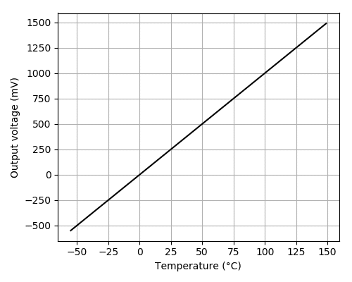
Note that the sensor operates on a voltage range of 4 to 30 V and that the output voltage is independent of the supply voltage.
The LM35 is part of a series of analog temperature sensors sold by Texas Instruments. Other members of the series include:
- LM335 – output voltage directly proportional to the absolute temperature at 10 mV/°K.
- LM34 – output voltage linearly proportional to Fahrenheit temperature 10 mV/°F.
LM35 pinout
The LM35 comes in 4 different packages, but the most common type is the 3-pin TO-92 transistor package.
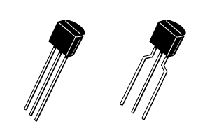
The pinout of the sensor is as follows:
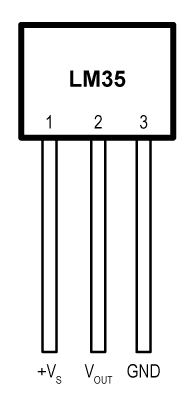
Note that pin 1 (+VS) is the leftmost pin when the flat side of the sensor (with the text printed on it) is facing towards you.
| Name | Pin | Description |
|---|---|---|
| +VS | 1 | Positive power supply pin (4 – 30 V) |
| VOUT | 2 | Temperature sensor analog output |
| GND | 3 | Device ground pin, connect to power supply negative terminal |
You can find the specifications of the LM35 in the table below.
LM35 analog temperature sensor specifications
| Supply voltage | 4 V to 30 V |
| Operating current | 60 µA |
| Temperature range | -55°C to + 155°C |
| Ensured accuracy | ±0.5°C at +25°C ±1°C from -55°C to +150°C |
| Output scale factor | 10 mV/°C |
| Output voltage at 25°C | 250 mV |
| Self-heating | <0.1°C in still air |
| Package | 3-pin TO-92 |
| Manufacturer | Texas Instruments |
| Cost | Check price |
For more information, you can also check out the datasheet here:
Wiring – Connecting LM35 analog temperature sensor to Arduino
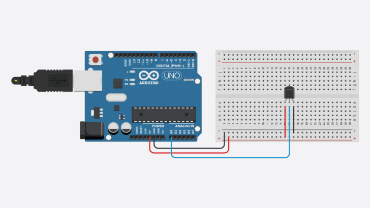
Connecting an LM35 to the Arduino is very easy as you only need to connect 3 pins. Start by connecting the +VS pin to the 5 V output of the Arduino and the GND pin to the ground.
Next, connect the middle pin (VOUT) to any of the analog inputs of the Arduino. In this case, I used the analog input pin A0.
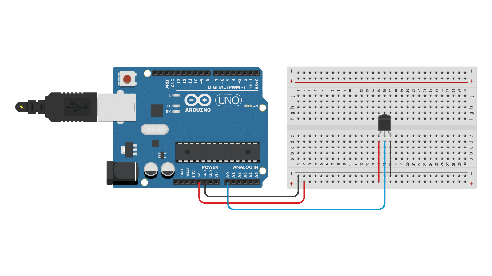
The connections are also given in the table below:
LM35 analog temperature sensor connections
| LM35 | Arduino |
|---|---|
| Pin 1 (+VS) | 5 V |
| Pin 2 (VOUT) | Pin A0 |
| PIN 3 (GND) | GND |
Converting the LM35 output voltage into temperature
To convert the output voltage of the sensor into the temperature in degree Celsius, you can use the following formula:
Temperature (°C) = VOUT / 10
with VOUT in millivolt (mV). So if the output of the sensor is 750 mV, the temperature is 75°C.
As you can see in the wiring diagram above, the output of the LM35 is connected to one of the analog inputs of the Arduino. The value of this analog input can be read with the function analogRead(). However, this function will not actually return the output voltage of the sensor.
Arduino boards contain a multichannel, 10-bit analog to digital converter (ADC), which will map input voltages between 0 and the operating voltage (5 V or 3.3 V) into integer values between 0 and 1023. On an Arduino Uno, for example, this yields a resolution between readings of 5 volts / 1024 units or, 0.0049 volts (4.9 mV) per unit.
So if you use analogRead() to read the voltage at one of the analog inputs of the Arduino, you will get a value between 0 and 1023.
To convert this value back into the output voltage of the sensor, you can use:
VOUT = reading from ADC * (Vref / 1024)
We will use these formulas in the code examples below.
LM35 analog temperature sensor with Arduino example code
With the following example code, you can read the temperature from an LM35 sensor and display it in the Serial Monitor.
You can upload the example code to your Arduino using the Arduino IDE.
/* LM35 analog temperature sensor with Arduino example code. More info: https://www.makerguides.com */

// Define to which pin of the Arduino the output of the LM35 is connected:
#define sensorPin A0

void setup() {
  // Begin serial communication at a baud rate of 9600:
  Serial.begin(9600);
}

void loop() {
  // Get a reading from the temperature sensor:
  int reading = analogRead(sensorPin);

  // Convert the reading into voltage:
  float voltage = reading * (5000 / 1024.0);

  // Convert the voltage into the temperature in degree Celsius:
  float temperature = voltage / 10;

  // Print the temperature in the Serial Monitor:
  Serial.print(temperature);
  Serial.print(" \xC2\xB0"); // shows degree symbol
  Serial.println("C");

  delay(1000); // wait a second between readings
}
You should see the following output in the Serial Monitor:
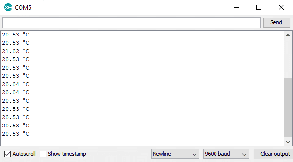
Make sure that the baud rate of the Serial Monitor is also set to 9600.
How the code works
First, I defined to which pin of the Arduino the VOUT pin of the sensor is connected. In this case, we used the analog pin A0. The statement #define can be used to give a name to a constant value. The compiler will replace all references to this constant with the defined value when the program is compiled. So everywhere you mention sensorPin, the compiler will replace it with A0 when the program is compiled.
// Define to which pin of the Arduino the output of the LM35 is connected:
#define sensorPin A0
In the setup section of the code, we begin serial communication at a baud rate of 9600.
void setup() {
  // Begin serial communication at a baud rate of 9600:
  Serial.begin(9600);
}
In the loop section of the code, we start by taking a reading from the sensor with the function analogRead(pin).
  // Get a reading from the temperature sensor:
  int reading = analogRead(sensorPin);
Next, we use the formulas that I mentioned earlier in the article to convert the reading into voltage and then into temperature.
  // Convert the reading into voltage:
  float voltage = reading * (5000 / 1024.0);

  // Convert the voltage into the temperature in degree Celsius:
  float temperature = voltage / 10;
Lastly, the results are printed in the Serial Monitor:
  // Print the temperature in the Serial Monitor:
  Serial.print(temperature);
  Serial.print(" \xC2\xB0"); // shows degree symbol
  Serial.println("C");
Improve the precision of the readings
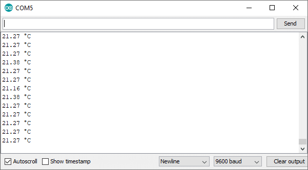
Because we used the default reference voltage of the Arduino for analog input (i.e. the value used as the top of the input range), the maximum resolution we get from the ADC is 5000/1024 = 4.88 mV or 0.49°C.
If we want a higher precision, we can use the built-in 1.1 V reference from the Arduino instead. This reference voltage can be changed using the function analogReference().
With 1.1 V as the reference voltage, we get a resolution of 1100/1024 = 1.07 mV or 0.11°C. Note that this limits the temperature range that we can measure to 0 to 110 degrees Celsius.
I have highlighted the lines you need to add/change in the code below:
/* LM35 analog temperature sensor with Arduino example code. More info: https://www.makerguides.com */

// Define to which pin of the Arduino the output of the LM35 is connected:
#define sensorPin A0

void setup() {
  // Begin serial communication at a baud rate of 9600:
  Serial.begin(9600);

  // Set the reference voltage for analog input to the built-in 1.1 V reference:
  analogReference(INTERNAL);
}

void loop() {
  // Get a reading from the temperature sensor:
  int reading = analogRead(sensorPin);

  // Convert the reading into voltage:
  float voltage = reading * (1100 / 1024.0);

  // Convert the voltage into the temperature in degree Celsius:
  float temperature = voltage / 10;

  // Print the temperature in the Serial Monitor:
  Serial.print(temperature);
  Serial.print(" \xC2\xB0"); // shows degree symbol
  Serial.println("C");

  delay(1000); // wait a second between readings
}
LM35 with I2C LCD and Arduino example code
If you want to make a standalone thermometer that doesn’t need a computer, it can be nice to know how to display the temperature readings on an LCD display.
With the example code below, you can display the temperature readings on a 16×2 character I2C LCD.
Connecting the I2C LCD is fairly easy as you can see in the wiring diagram below. You can check out my detailed tutorial on How to control a character I2C LCD with Arduino for more information. If you want to use a standard non-I2C LCD instead, take a look at How to use a 16×2 character LCD with Arduino.
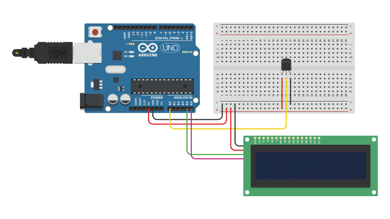
The connections are also given in the table below:
I2C LCD Connections
| I2C Character LCD | Arduino |
|---|---|
| GND | GND |
| VCC | 5 V |
| SDA | A4 |
| SCL | A5 |
Note that the LM35 temperature sensor is connected in the same way as before.
Installing the required Arduino libraries
To use an I2C LCD, you need to install the LiquidCrystal_I2C Arduino library.
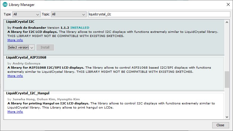
To install this library, go to Tools > Manage Libraries (Ctrl + Shift + I on Windows) in the Arduino IDE. The Library Manager will open and update the list of installed libraries.
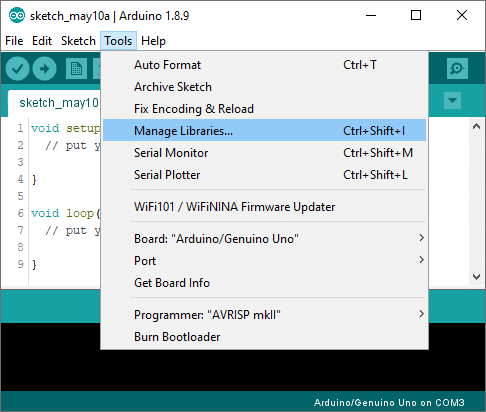
Now search for ‘liquidcrystal_i2c’ and look for the library by Frank de Brabander. Select the latest version and then click Install.
LM35 with I2C LCD example code
/* LM35 analog temperature sensor with I2C LCD and Arduino example code. More info: https://www.makerguides.com */

// Include the required Arduino libraries:
#include "LiquidCrystal_I2C.h"

// Create a new instance of the LiquidCrystal_I2C class:
LiquidCrystal_I2C lcd(0x27, 16, 2);

// Degree symbol:
byte Degree[] = {
  B00111,
  B00101,
  B00111,
  B00000,
  B00000,
  B00000,
  B00000,
  B00000
};

// Define to which pin of the Arduino the output of the LM35 is connected:
#define sensorPin A0

void setup() {
  // Start the LCD and turn on the backlight:
  lcd.init();
  lcd.backlight();

  // Create a custom character:
  lcd.createChar(0, Degree);
}

void loop() {
  // Get a reading from the temperature sensor:
  int reading = analogRead(sensorPin);

  // Convert the reading into voltage:
  float voltage = reading * (5000 / 1024.0);

  // Convert the voltage into the temperature in degree Celsius:
  float temperature = voltage / 10;

  // Print the temperature on the LCD;
  lcd.setCursor(0, 0);
  lcd.print("Temperature:");
  lcd.setCursor(0, 1);
  lcd.print(temperature);
  lcd.write(0); // print the custom character
  lcd.print("C");

  delay(1000); // wait a second between readings
}
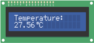
You should see the following output on the LCD:
Conclusion
In this tutorial, I have shown you how to use an LM35 analog temperature sensor with Arduino. I hope you found it useful and informative. If you did, please share this article with a friend who also likes electronics and making things.
I would love to know what projects you plan on building (or have already built) with this sensor. If you have any questions, suggestions, or if you think that things are missing in this tutorial, please leave a comment below.
Note that comments are held for moderation to prevent spam.

This work is licensed under a Creative Commons Attribution-NonCommercial-ShareAlike 4.0 International License.
Other Useful Links From Around The Web:
Benne is professional Systems Engineer with a deep expertise in Arduino and a passion for DIY projects.

Philip
Monday 26th of June 2023
The statement for Vout is wrong. To determine the voltage returned by the analogRead(): Vout = (reading from ADC *(Vref/1023) >>> NOT 1024! 1024 is the number of possible readings from the ADC but one of those readings is 0 which is the starting point. The number of discrete segments is 1023. The reading should be divided by the highest number of segments. For example, suppose the ADC returned a number between 0 and 10. To find the proportion, the number would be divided by 10 (the highest reading) and not by 11 (the number of possible readings including 0).