This article will give you all the necessary information about the Serial Peripheral Interface (SPI) communication protocol of the AVR microcontroller used in Arduino UNO and Arduino Mega board.
I have included a detailed specification, pin diagram, and code for SPI communication between two Arduino boards. I have also included Arduino SPI read example with the RFID-RC522 reader.
After this article, you will learn how to use the SPI protocol and read/write data via the SPI protocol.
Supplies
Hardware components
Software
| Arduino IDE | Arduino IDE |
Makerguides.com is a participant in the Amazon Services LLC Associates Program, an affiliate advertising program designed to provide a means for sites to earn advertising fees by advertising and linking to products on Amazon.com.
Basic of SPI Communication Protocol
Motorola founded SPI (Serial Peripheral Interface) interface in 1970. SPI is a synchronous serial communication and full-duplex protocol.
This means that data can be transferred in both directions at the same time simultaneously. It can also be set for half-duplex mode.
What is SPI?
SPI is a synchronous serial communication protocol to transfer the data with rising or falling edge of clock pulse between two microcontrollers or between the microcontroller and SPI peripheral devices.
SPI device can be set as Master or Slave, and only the Master can generate clock pulses and initiate the communication.
However, once the communication begins, both Master and Slave can transmit the data simultaneously. It is also known as the four-wire protocol.
SPI communication uses four wires MISO, MOSI, CLK, and CS/SS. An SPI can have only one Master and can have multiple slaves.
A Master is usually a microcontroller, and the slaves can be a microcontroller or any peripherals such as sensors, ADC, DAC, LCD, RTC, etc.
SPI Master-Slave Interfacing
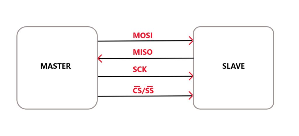
SPI protocol contains four lines MISO, MOSI, SCK, and CS/SS.
MOSI (Master Out Slave In) – Using MOSI pin Master sends data to Slave.
MISO (Master In Slave Out) – Using MISO Slave can send data to the Master.SCK (Serial Clock) – The Master generates the clock signal, and it provides synchronization between Master and Slave.
CS (Chip Select) – Using CS or Slave Select (SS), Master can select Slave. This is an active-low pin, so you need to set this pin low for selecting the Slave device.
SPI Master with Multiple Slaves
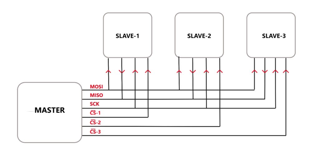
SPI protocol allows you to have multiple SPI devices sharing the same MOSI, MISO, and CLK lines of the Master.
As you can observe in the above diagram, there are three slaves in which the MOSI, MISO, SCK are commonly connected to the Master, and the CS of each slave are connected separately to individual CS pins of the master.
Does Arduino Uno have SPI?
Yes, the Arduino Uno board comes with an AVR ATMEGA328p microcontroller, and it has one SPI interface on the board.
So, to use SPI in Arduino Uno and set different modes and speeds, you need to learn about the SPI register in AVR MCUs.
What are the SPI Registers in AVR?
AVR Series uses three registers to configure SPI communication that is SPI Control Register (SPCR), SPI Status Register (SPSR), and SPI Data Register (SPDR).
SPI Control Register (SPCR)
The default value of the SPCR Register is 0x00.
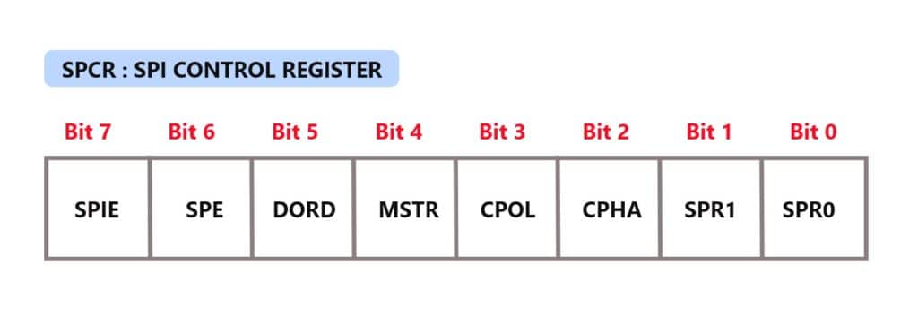
Bit 7 is SPIE, SPI Interrupt Enable bit. You can enable SPI Interrupt by setting the bit high and disabling it by setting the bit low.
Bit 6 is SPE, SPI Enable bit. You need to set this bit high to enable the SPI.
Bit 5 is DORD, Data Order bit. If the bit is set, then it transmits LSB first. If the bit is clear, then MSB is transmitted first.
Bit 4 is MSTR, Master/Slave Select bit. Set for Master mode and clear the bit for Slave mode.
Bit 3 is CPOL, Clock Polarity Select bit. If set, clocks start from logic one, and if clear, the clock starts from logic zero.
Bit 2 is CPHA, Clock Phase Select bit.The Clock Polarity (CPOL) and Clock Phase (CPHA) bits define how serial data is transferred between the Master and the Slave.
If the bit is set, then the data sample is on the trailing clock edge, and if it is clear, then the data sample is on the leading clock edge.
| CPOL | CPHA | Leading edge | Trailing Edge |
| 0 | 0 | Sample (Rising) | Setup (Falling) |
| 0 | 1 | Setup (Rising) | Sample (Falling) |
| 1 | 0 | Sample (Falling) | Setup (Rising) |
| 1 | 1 | Setup (Falling) | Sample (Rising) |
Bit 1:0 are SPR1-SPR0 SPI Clock Rate Select bits. The below table shows the SCK clock frequency select bit settings.
| SPI2X | SPR1 | SPR0 | Clock frequency |
| 0 | 0 | 0 | Fosc/4 |
| 0 | 0 | 1 | Fosc/16 |
| 0 | 1 | 0 | Fosc/64 |
| 0 | 1 | 1 | Fosc/128 |
| 1 | 0 | 0 | Fosc/2 |
| 1 | 0 | 1 | Fosc/8 |
| 1 | 1 | 0 | Fosc/32 |
| 1 | 1 | 1 | Fosc/64 |
SPI Status Register (SPSR)
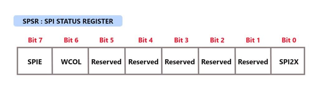
Bit 7 – SPIF: SPI interrupt flag bit.
When the serial data transfer is complete, this flag gets set.
It also gets set when the SS pin is driven low in Master mode.
Bit 6 – WCOL: Write Collision Flag bit. This bit is set when SPI data register writes occur during previous data transfer.
Bit 5:1 – Reserved Bits. These bits are reserved bits, and they will always read as zero.
Bit 0 – SPI2X: Double SPI Speed bit. If SPI speed (SCK Frequency) gets doubled when set this bit.
SPI Data Register (SPDR)
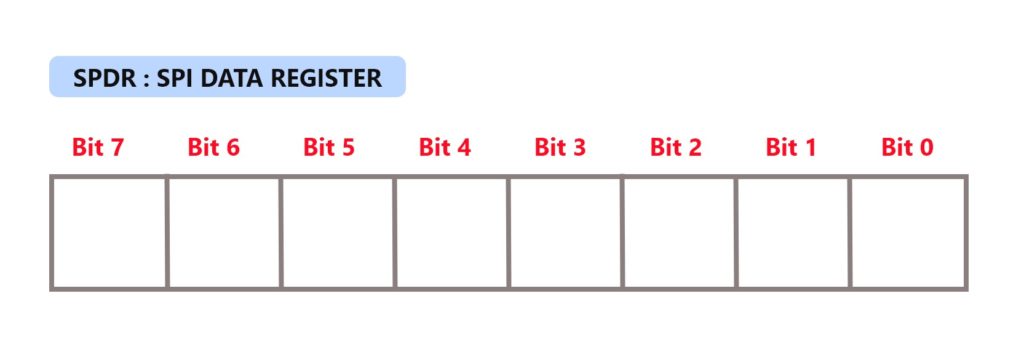
The SPI Data Register is a read/write register. It is used for data transfer between the Register File and the SPI Shift Register.
Writing to the register initiates data transmission.
Reading the register causes the Shift Register Receive buffer to be read.
What is SPI in Arduino?
Suppose you use Arduino Uno or Arduino Mega and want to transfer data serially between two SPI devices.
In that case, this part of the article will help you get started with SPI in the Arduino framework.
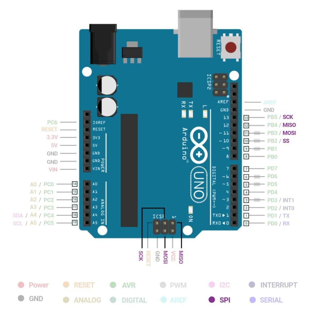
What are SPI pins in Arduino Uno?
Arduino Uno has one SPI communication interface. Pin 10 (CS/SS), 11 (MOSI), 12 (MISO), and 13 (SCK).
| SPI Function | Pin in Arduino |
| MOSI | 11 or ICSP-4 |
| MISO | 12 or ICSP-1 |
| SCK | 13 or ICSP-3 |
| CS | 10 |
Where is the Arduino SPI library?
There is a readily available library for SPI communication in the Arduino framework. To use the SPI library, you need to include #include <SPI.h> in your code.
To use the SPI library, you need to consider the following points.
- Enable SPI communication
- Select mode as Master or Slave
- Do you want to send Most Significant Bit (MSB) or Least Significant Bit (LSB) first?
- Set clock idle as high or low
- Set sample on the falling or rising edge of clock pulses
- Speed of SPI communication
What is the maximum speed of SPI?
You can set the speed of SPI by setting parameters in SPISettings. The speed of SPI will depend upon the chip rate.
For example, if you use a chip rated at 16 MHz, then use 16000000 in SPISettings.
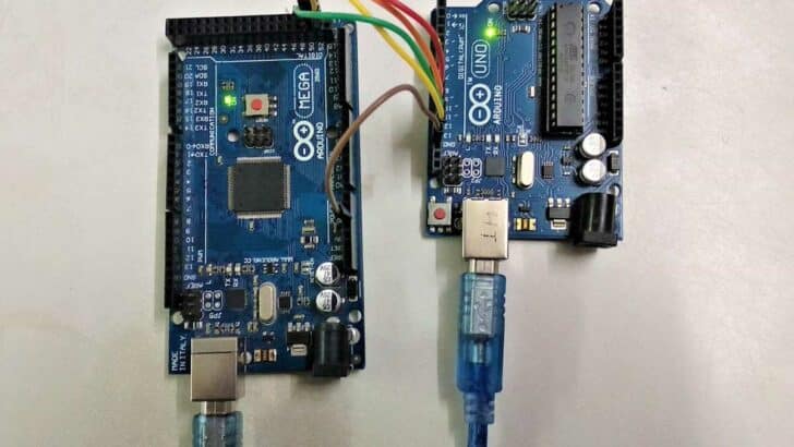
How do I connect two Arduinos with SPI?
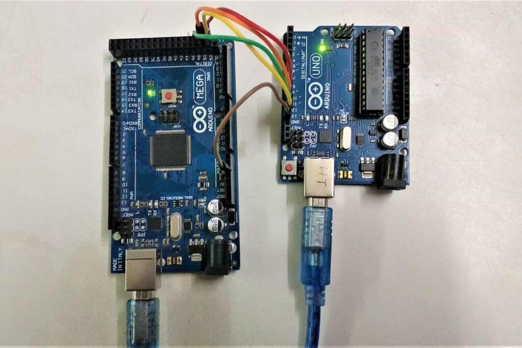
In this section, you will learn about interfacing of two Arduino Uno boards, Arduino Uno and Arduino Mega boards, for SPI communication.
Make sure that the ground of two boards is common.
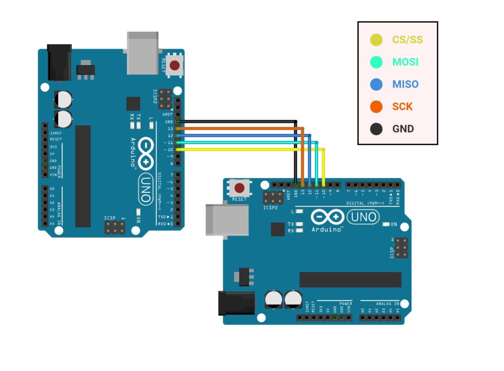
Interfacing of two Arduino Uno Boards for SPI
| SPI Pin | Arduino Uno-1 | Arduino Uno-2 |
| CS/SS | 10 | 10 |
| MOSI | 11 | 11 |
| MISO | 12 | 12 |
| SCK | 13 | 13 |
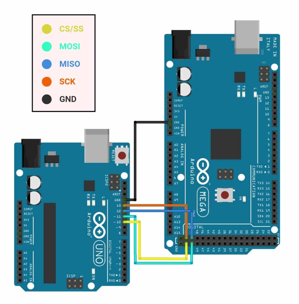
Interfacing of Arduino Uno Board and Arduino Mega Board for SPI
| SPI Pin | Arduino UNO | Arduino Mega |
| CS/SS | 10 | 53 |
| MOSI | 11 | 51 |
| MISO | 12 | 50 |
| SCK | 13 | 52 |
How do you write an SPI code?
To write a code for SPI communication between two Arduino boards, first, you need to set one board as Master and another as a slave.
Following are the codes for setting Arduino Uno or Mega as Master and slave.
Arduino Code for Master Mode
# include "SPI.h"
char str[ ]="Hello Slave, I'm Arduino Family\n";
void setup() {
Serial.begin(115200); // set baud rate to 115200 for usart
SPI.begin();
SPI.setClockDivider(SPI_CLOCK_DIV8); //divide the clock by 8
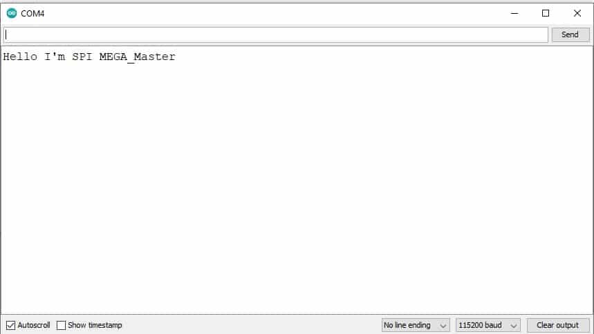
Serial.println("Hello I'm SPI Mega_Master");
}
void loop (void) {
digitalWrite(SS, LOW); // enable Slave Select
// send test string
for(int i=0; i< sizeof(str); i++)
SPI.transfer(str[i]);
digitalWrite(SS, HIGH); // disable Slave Select
delay(2000);
}
How the code works for Master Mode
First, you need to include a header file to use the SPI library.
# include "SPI.h"
SPI.begin() function is based on the SPI bus by setting SCK, MOSI, and CS to Initialize as an output, pulling SCK and MOSI low, and SS high for Arduino boards.
By default, the code work in Master mode.
SPI.setClockDivider(divider) function is to Set the SPI clock divider relative to the system clock. The available dividers are 2, 4, 8, 16, 32, 64, or 128.
The default setting is SPI_CLOCK_DIV4, which sets the SPI clock to one-quarter of the frequency of the system clock (5 Mhz for the boards at 20 MHz).
Now, in the void loop, you need to set CS/SS pin as low to select the slave device, then you can transfer the data using SPI.transfer, and finally, in the end, set CS/SS pin as high to disable the slave connection.
digitalWrite(SS, LOW); // enable Slave Select
 // send test string
 for(int i=0; i< sizeof(str); i++)
    SPI.transfer(str[i]);
 digitalWrite(SS, HIGH); // disable Slave Select
 delay(2000);
Arduino Code for Slave Mode
#include "SPI.h"
char str[50];
volatile byte i;
volatile bool pin;
void setup()
{
Serial.begin (115200); // set baud rate to 115200 for usart
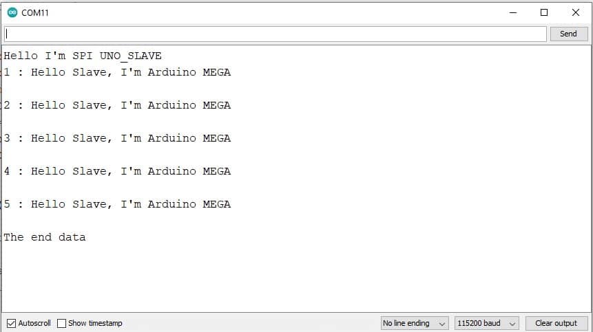
Serial.println("Hello I'm SPI UNO_SLAVE");
pinMode(MISO, OUTPUT); // have to send on Master in so it set as output
SPCR |= _BV(SPE); // turn on SPI in slave mode
i = 0; // buffer empty
pin = false;
SPI.attachInterrupt(); // turn on interrupt
}
void loop(){
static int count;
if (pin)
{
pin = false; //reset the pin
if(count++< 5){
Serial.print(count);
Serial.print(" : ");
Serial.println(str); //print the array on serial monitor
if(count==5)
{
delay(1000);
Serial.println("The end data");
}
delay(1000);
i= 0; //reset button to zero
}
}
// Interrupt function
ISR(SPI_STC_vect)
{
char c = SPDR; // read byte from SPI Data Register
if (i < sizeof(str)) {
str [i++] = c; // save data in the next index in the array buff
if ( (c == '\r') || (c == '\n') || (c=='\0') ) //check for the end of the word
pin = true;
}
}
How the code works for Slave Mode
To use the Arduino board as a Slave device, you need to set the MISO pin as output and turn ON the Slave mode. Also, you need to attach interrupt so that you can handle the data received by the Master.
pinMode(MISO, OUTPUT); // have to send on Master in so it set as output
SPCR |= _BV(SPE); // turn on SPI in slave mode
SPI.attachInterrupt(); // turn on interrupt
Whenever an interrupt is generated due to data from the master device, in Slave, the pointer will jump to ISR with the address of SPI_STC_vect, and it will copy the data from SPDR to variable c and finally from c to the str array.
ISR(SPI_STC_vect)
{
  char c = SPDR;        // read byte from SPI Data Register
  if (i < sizeof(str)) {
    str [i++] = c; // save data in the next index in the array buff
    if ( (c == '\r') || (c == '\n') || (c=='\0') ) //check for the end of the word
      pin = true;
  }
}
Finally, in the void loop, received data is printed on the serial terminal.
Serial monitor output for Master and Slavedevices is shown below.
Master device output:
Slave Device output:
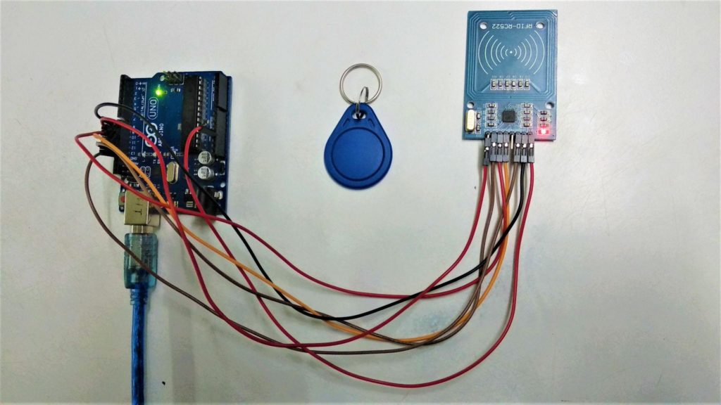
How to use the RFID-RC522 module (RFID reader) with the Arduino UNO
Now, I will provide you code and interfacing diagram of RFID (Radio Frequency Identification) with Arduino Uno.
RFID is a system for transferring data over short distances. I will use the RC522 RFID reader and passive tags.
Interfacing of RFID-RC522 Module with Arduino Uno
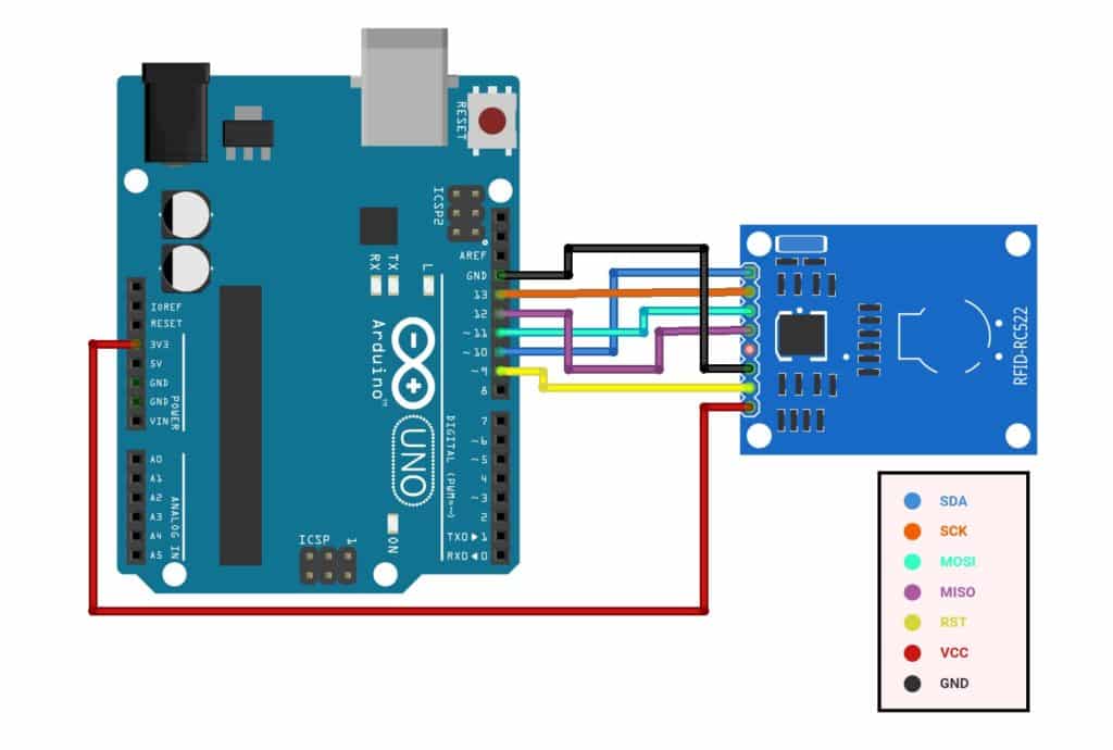
| RFID-RC522 Module | Arduino Uno |
| SDA | Digital 10 |
| SCK | Digital 13 |
| MOSI | Digital 11 |
| MISO | Digital 12 |
| IRQ | Not Connected |
| GND | GND |
| RST | Digital 9 |
| 3.3V | 3.3V |
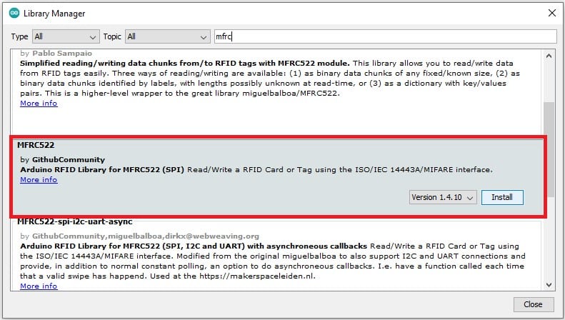
Arduino Code for RFID-RC522
You need to install the RFID library in your Arduino IDE. Go to Tools > Manage Libraries.
In the search box, type “mfrc” and install the MFRC522 SPI library.
#include "SPI.h"
#include "MFRC522.h"
#define chipS 10
#define RESET 9
MFRC522 mfrc522(chipS, RESET); // Create MFRC522 instance.
void setup()
{
Serial.begin(115200); // Initiate a serial communication
SPI.begin(); // Initiate SPI bus
mfrc522.PCD_Init(); // Initiate MFRC522
Serial.println("Scan your card to the RFID Reader...");
Serial.println();
}
void loop()
{
if ( ! mfrc522.PICC_IsNewCardPresent()) // Look for new card
{
return;
}
if ( ! mfrc522.PICC_ReadCardSerial()) // Select one of the cards
{
return;
}
Serial.print("UID tag :"); // Show UID on serial monitor
String content= "";
byte letter;
for (byte i = 0; i < mfrc522.uid.size; i++)
{
Serial.print(mfrc522.uid.uidByte[i] < 0x10 ? " 0" : " ");
Serial.print(mfrc522.uid.uidByte[i], HEX);
content.concat(String(mfrc522.uid.uidByte[i] < 0x10 ? " 0" : " "));
content.concat(String(mfrc522.uid.uidByte[i], HEX));
}
Serial.println();
Serial.print("Reader MSG : ");
content.toLowerCase();
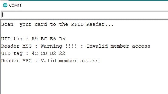
if ((content.substring(1) == "4c cd d2 22") ) //change here the UID of the card/cards
{
Serial.println("Valid member access");
Serial.println();
delay(2000);
}
else {
Serial.print("Warning !!!!");
Serial.print(" : ");
Serial.println("Invalid member access");
delay(2000);
}
}
Serial Monitor Output:
Conclusion
In this article, I have shown you how to setup SPI communication between two Arduino boards and SPI read example for RFID with Arduino Uno board.
I hope you found this article informative. If you did, please share it with a friend who likes electronics and making things!
If you have any questions or suggestions, or if you think things are missing in this tutorial, please leave a comment below.
Note that comments are held for moderation to prevent spam.

Hiren is a professional Embedded Engineer with a Master’s Degree
in Electronics and Communication Engineering. He is proficient in C and
C++ and enjoys building DIY projects on Arduino, ESP32, PIC32, STM32 & Raspberry PI boards.
Daniel
Sunday 17th of July 2022
I think your clock settings bit values are wrong.
LZ
Sunday 27th of March 2022
"have to send on Master in so it set as output" Przecież dzieje się odwrotnie w tym kodzie - to master wysyła a slave odczytuje. Jak można takie nonsensy przepuszczać.