There are many temperature sensor options to utilise when sensing the ambient temperature with Arduino.
You can use NTC/PTC, thermocouple or an RTD sensors. When you need the best accuracy possible, RTD sensors are the unanimous choice.
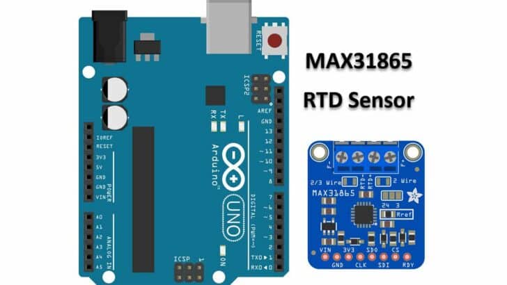
You can use the MAX31865 IC to interface RTD sensors such as PT100 or PT1000. You will find the MAX31865 modules easily available online..
This article will teach us how to use a MAX31865 IC with the RTD sensor to read the temperature.
We will understand the IC’s basics and the different configurations possible for the RTD sensors.
In the following sections, I will present connection diagrams, Arduino code for the RTD sensor, and more.
In the last section of the article, you will find the answers to the most frequently asked questions about the MAX31865 IC and the RTD sensors.
Let’s get started!
Components Needed To Build Arduino MAX31865 RTD Sensor Project
Hardware Components
- Dupont wire x 1 set
- Arduino USB cable (for powering Arduino and programming) x 1
Software
Makerguides.com is a participant in the Amazon Services LLC Associates Program, an affiliate advertising program designed to provide a means for sites to earn advertising fees by advertising and linking to products on Amazon.com.
Basics of The MAX31865 RTD Sensor
In this section, we will see the basics of RTD sensing and the MAX31865 IC, which is a resistance-to-digital converter mainly used with RTD sensors.
The MAX31865 IC measures the resistance and converts the resistance to an equivalent digital value.
The IC can also report if the sensor condition is open or short-circuit.
Here are the key features of the MAX31865 temperature IC:
- Handles PT100 to PT1000 sensors.
- Simplifies the circuit design and lowers the project development time.
- Supports 2-wire, 3-wire, and 4-wire RTD sensors.
- 15-bit ADC resolution helps in achieving the best accuracy.
- Maximum conversion time is 21 ms.
The below image shows the typical connections needed.

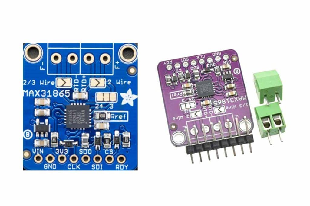
The MAX31865 IC comes in two packages. The pin names and descriptions are provided in the table below.
| Pin Name | Pin Description |
| BIAS | Bias Voltage Output (VBIAS) |
| REFIN+ | Positive Reference Voltage Input. Connect to BIAS. Connect the reference resistor between REFIN+ and REFIN-. |
| REFIN- | Negative Reference Voltage Input. Connect the reference resistor between REFIN+ and REFIN-. |
| ISENSOR | Low Side of RREF. Connect to REFIN-. |
| FORCE+ | High-Side RTD Drive. Connect to FORCE2 when using the 3-wire connection configuration. Protected to ±45V. |
| FORCE2 | Positive Input Used in 3-Wire Only. When in the 3-wire connection configuration, connect to FORCE+. When in the 2-wire or 4-wire connection configuration, connect to the ground. Protected to ±45V. |
| RTDIN+ | Positive RTD Input. Protected to ±45V. |
| RTDIN- | Negative RTD Input. Protected to ±45V. |
| FORCE- | Low-Side RTD Return. Protected to ±45V. |
| GND2 | Analog Ground. Connect to GND1. |
| SDI | Serial-Data Input |
| SCLK | Serial-Data Clock Input |
| CS | Active-Low Chip Select. Set CS low to enable the serial interface. |
| SDO | Serial-Data Output |
| DGND | Digital Ground |
| GND1 | Analog Ground. Connect to GND2. |
| N.C. | Do Not Connect |
| DRDY | Active-Low, Push-Pull, Data-Ready Output. DRDY goes low when a new conversion result is available in the data register. When a read operation of an RTD resistance data register occurs, DRDY returns high. |
| DVDD | Digital Supply Voltage Input. Connect to a 3.3V power supply. Bypass to DGND with a 0.1µF bypass capacitor. |
| VDD | Analog Supply Voltage Input. Connect to a 3.3V power supply. Bypass to GND1 with a 0.1µF bypass capacitor. |
| EP | Exposed Pad (Bottom Side of Package). Connect to GND1. Applies to TQFN package only. |
The Arduino code will read the registers to get the temperature value and sensor status message.
The table below summarises the details of the register names and the corresponding address of the registers:
| REGISTER NAME | READ ADDRESS (HEX) | WRITE ADDRESS (HEX) | POR STATE | READ /WRITE |
| Configuration | 00h | 80h | 00h | R/W |
| RTD MSBs | 01h | — | 00h | R |
| RTD LSBs | 02h | — | 00h | R |
| High Fault Threshold MSB | 03h | 83h | FFh | R/W |
| High Fault Threshold LSB | 04h | 84h | FFh | R/W |
| Low Fault Threshold MSB | 05h | 85h | 00h | R/W |
| Low Fault Threshold LSB | 06h | 86h | 00h | R/W |
| Fault Status | 07h | — | 00h | R |
The equation below is known as Callender-Van Dusen Equation. You can use the equation to convert the input resistance.

The below equation is more straightforward and is valid from 0 °C s up to 660 °C.
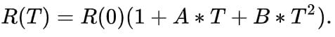
Where
A = 3.9083 x 10⁻³
B = –5.775x 10⁻⁷
C = –4.183 x 10⁻¹²
The RTD sensors come in many options. The three options are presented in the image below.
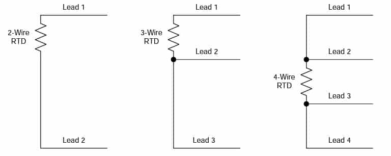
In the case of the 2-wire option, you cannot separate the lead resistance from the PT100 element resistance.
Hence you will have an error you cannot remove from the readings.
In the case of the 3-wire option, you can cancel the resistance of the lead wire and produce results close to ideal. Here, you assume that the resistance of the leads matches.
The 4-wire configurations are the most expensive but provide superior accuracy over the other two.
The RTD resistance is sensed without the side effect of lead resistance.
In the next section, we will follow the step-by-step connection guide to complete the required wiring between Arduino UNO and the MAX31865 IC.
Step-By-Step Instructions To Connect The RTD Sensor MAX31865 With Arduino UNO
In this section, we will build a project using Arduino UNO and the RTD sensor MAX31865.
I will cover the hardware connections and provide you with some example code as well.
How To Connect The RTD Sensor MAX31865 to the Arduino UNO?
Below is the step-by-step connection guide to complete the Arduino and the resistance to temperature sensor interface IC MAX31865.
In this project, you will interface MAX31865 IC to the Arduino UNO via SPI protocol.
Step 1: Start with the GND connections
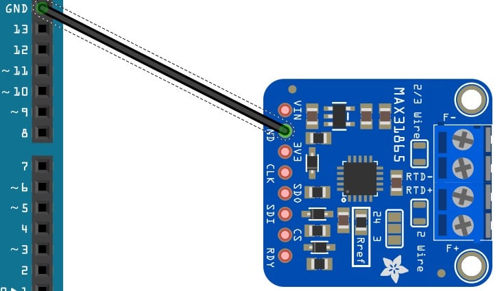
You can choose any GND pins on the Arduino to complete the GND connections. It is a good practice to connect the GND pins first.
Step 2: Connect the SCLK pin
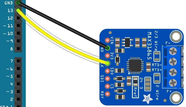
Connect the CLK pin of the MAX31865 module to Pin 13 of the Arduino. You can also connect the CLK pin to other GPIO pins of the Arduino UNO.
Please don’t forget to update the Arduino sketch.
Step 3: Connect the SDO pin.
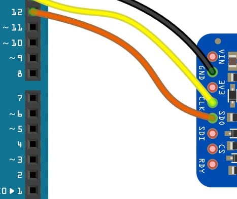
Connect the SDO pin of the MAX31865 module to Pin 12 of the Arduino.
Step 4: Connect the SDI pin.
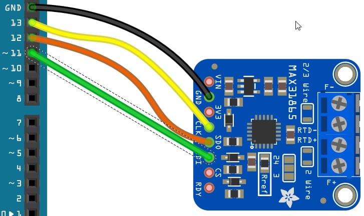
Connect the SDI pin of the MAX31865 module to Pin 11 of the Arduino.
Step 5: Connect the CS pin.
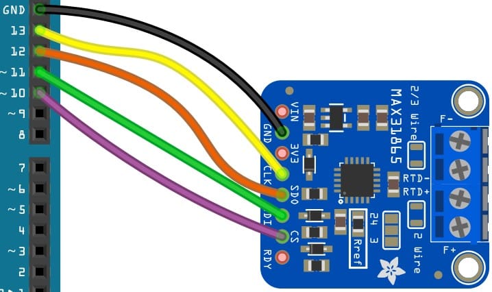
Connect the CS pin of the MAX31865 module to Pin 10 of the Arduino.
You can also connect the SPI-related pins to other GPIO pins of the Arduino UNO. Please don’t forget to update the Arduino sketch.
Step 6: Connect the Power pin.
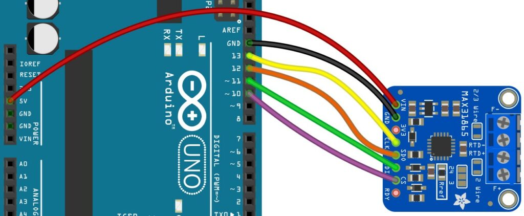
Connect the VIN pin of the MAX31865 RTD sensor module to Arduino UNO.
Connect the RTD sensor to the terminal connectors provided. Follow the label provided on the board.
Congratulations! You have completed all the essential connections required for the Arduino and the MAX31865 RTD sensor module interface.
Arduino Code Example For The MAX31865 RTD Sensor Project
In this section, you will find the Arduino sketch required to build a basic temperature sensing project using the MAX31865 RTD sensor.
We will use the Adafruit library to test our project. If the library still needs to be installed, follow the steps below to install it.
Go to Tools → Manage Library → Search for MAX81365
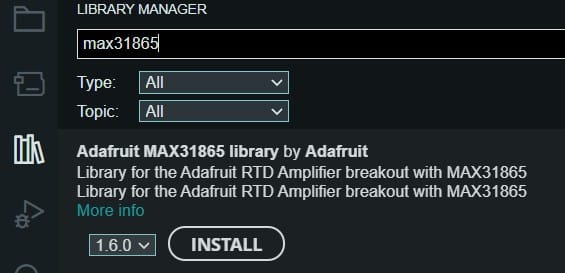
Click on Install. If you get a prompt asking to install additional dependency libraries, say yes.
The complete Arduino code for the MAX31865 IC
#include "Adafruit_MAX31865.h"

// Use software SPI: CS, DI, DO, CLK
Adafruit_MAX31865 thermo = Adafruit_MAX31865(10, 11, 12, 13);
// use hardware SPI, just pass in the CS pin
//Adafruit_MAX31865 thermo = Adafruit_MAX31865(10);

// The value of the Rref resistor. Use 430.0 for PT100 and 4300.0 for PT1000
#define RREF      430.0
// The 'nominal' 0-degrees-C resistance of the sensor
// 100.0 for PT100, 1000.0 for PT1000
#define RNOMINAL  100.0

void setup() {
  Serial.begin(115200);
  Serial.println("Adafruit MAX31865 PT100 Sensor Test!");

  thermo.begin(MAX31865_3WIRE);  // set to 2WIRE or 4WIRE as necessary
}

void loop() {
  uint16_t rtd = thermo.readRTD();

  Serial.print("RTD value: "); Serial.println(rtd);
  float ratio = rtd;
  ratio /= 32768;
  Serial.print("Ratio = "); Serial.println(ratio,8);
  Serial.print("Resistance = "); Serial.println(RREF*ratio,8);
  Serial.print("Temperature = "); Serial.println(thermo.temperature(RNOMINAL, RREF));

  // Check and print any faults
  uint8_t fault = thermo.readFault();
  if (fault) {
    Serial.print("Fault 0x"); Serial.println(fault, HEX);
    if (fault & MAX31865_FAULT_HIGHTHRESH) {
      Serial.println("RTD High Threshold");
    }
    if (fault & MAX31865_FAULT_LOWTHRESH) {
      Serial.println("RTD Low Threshold");
    }
    if (fault & MAX31865_FAULT_REFINLOW) {
      Serial.println("REFIN- > 0.85 x Bias");
    }
    if (fault & MAX31865_FAULT_REFINHIGH) {
      Serial.println("REFIN- < 0.85 x Bias - FORCE- open");
    }
    if (fault & MAX31865_FAULT_RTDINLOW) {
      Serial.println("RTDIN- < 0.85 x Bias - FORCE- open");
    }
    if (fault & MAX31865_FAULT_OVUV) {
      Serial.println("Under/Over voltage");
    }
    thermo.clearFault();
  }
  Serial.println();
  delay(1000);
}
The lines below sets the software SPI pins. If you had to connect the SPI pins to other Arduino UNO pins, please change the below line accordingly.
// Use software SPI: CS, DI, DO, CLK
Adafruit_MAX31865 thermo = Adafruit_MAX31865(10, 11, 12, 13);
If you are using PT100, keep the below lines intact. If you are using PT1000, update RREF to 4300 and RNOMINAL to 1000.
// The value of the Rref resistor. Use 430.0 for PT100 and 4300.0 for PT1000
#define RREF      430.0
// The 'nominal' 0-degrees-C resistance of the sensor
// 100.0 for PT100, 1000.0 for PT1000
#define RNOMINAL  100.0
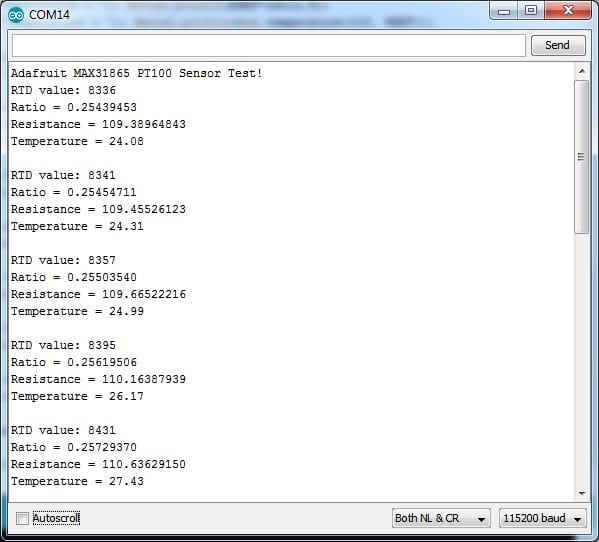
If the connections and programming were successful, you would find the log on the serial terminal similar to the one shown below. PT100 type sensor is used.
FAQs About The RTD Sensor MAX31865 And Arduino Projects
I have included a list of the most frequently asked questions about projects built using Arduino and the Resistance to digital converter IC MAX31865.
If you have any other questions related to RTD sensor MAX31865, please post them in the comments section.
I will be happy to answer them.
1. What is an RTD sensor used for?
An RTD sensor is used to convert the Resistance into a voltage. The MAX31865 IC converts the resistance value into a voltage that an Arduino UNO can process.
RTD stands for Resistor Temperature Detector. As the temperature changes, the Resistance will change too.
The RTD sensor needs dedicated ICs such as MAX31865 to provide useful results.
In this article, we have covered all the aspects required to build an RTD sensor project using the MAX31865 IC.
2. What does PT100 mean in RTD?
In RTD sensor applications, PT100 is the commonly used type of material. PT100 is a thin strip of platinum.
The Resistance of the strip at 0 ℃ is 100 ohms. Hence the name PT100.
PT refers to the fact that the sensor comprises platinum material. 100 refers to the fact that the Resistance, when measured, will be 100 Ohms at 0 ℃.
3. Can RTD measure temperature?
An RTD is the most widely used temperature sensor where accuracy is the priority.
RTD sensors provide the best accuracy, stability and repeatability.
Hence, RTD sensors are used in industrial and scientific applications.
4. What is the difference between PT100 and PT1000 RTD sensors?
Both PT100 and PT1000 sensors are Resistance to temperature sensors. The PT1000 resistance will be 1000 Ohms at 0 ℃, whereas PT100 will measure the resistance of 100 Ohms at 0 ℃.
PT1000 is cost-effective compared to PT100 due to higher Resistance and lower demand on the signal processing chain.
5. Why do RTDs have three wires?
You will find RTDs with 2,3, and 4-wire options as well. Two two-wire RTDs are not accurate because the lead connections will influence the voltage reading.
Every lead connection will have finite resistance.
Hence you will add another cable of the same length which will help compensate for the error introduced due to the lead resistance.
This is called a 3-wire RTD sensor.
The four-wire solution is the best out of all the versions. The four wire RTDs will produce the best accurate readings since the lead resistance inaccuracy is 100% compensated.
Conclusion
In this article, we went through the basic working principle, types, and wiring configurations of the RTD sensor and MAX31865 interface.
We covered the MAX31865 and Arduino UNO connection guide and Arduino code examples to verify the connections.
Please share the applications you are planning to use for RTD sensors.
MAX31865 is a versatile IC that uses RTD sensors with Arduino. I would love to hear about the projects you have built.
You can share them in the comments section.
If you have any feedback to improve the article, please share them in the comments section.
Your valuable input helps me to improve the article quality and bring more helpful content in the future.
Please remember to share the article with your fellow Arduino enthusiasts.

I am Puneeth. I love tinkering with open-source projects, Arduino, ESP32, Pi and more. I have worked with many different Arduino boards and currently I am exploring, Arduino powered LoRa, Power line communication and IoT.