In this tutorial, you will learn how to control a MAX7219 LED dot matrix display with Arduino. I have included a wiring diagram and many example codes! The code in this tutorial can be used for 8×8, 8×32, and even larger displays.
For this tutorial, I will be using the MD_Parola in combination with the MD_MAX72XX Arduino library. These libraries make displaying scrolling text and other animations super easy. In the first part of this article, I will cover the basics of printing text on the display. Next, we will look at scrolling text and other text animations. Lastly, I will show you how to use text sprites.
If you would like to learn more about other types of displays, check out the articles below:
Recommended articles
- Game of Life on a Dot Matrix Display with MAX7219
- TM1637 4 Digit 7 Segment Display Arduino Tutorial
- How to use a 16×2 character LCD with Arduino
- How to control a character I2C LCD with Arduino
If you have any questions, please leave a comment below.
Supplies
Hardware components
| 8×32 MAX7219 LED dot matrix display | × 1 | Amazon | |
| 8×8 MAX7219 LED dot matrix display (alternative) | × 1 | Amazon | |
| Generic 8×8 MAX7219 LED dot matrix display (alternative) | × 1 | Amazon | |
| Arduino Uno Rev3 | × 1 | Amazon | |
| Jumper wires (male to female) | × 4 | Amazon | |
| USB cable type A/B | × 1 | Amazon | |
| Male headers | ~ 20 | Amazon | |
| Jumpers | ~ 20 | Amazon |
Software
Makerguides.com is a participant in the Amazon Services LLC Associates Program, an affiliate advertising program designed to provide a means for sites to earn advertising fees by advertising and linking to products on Amazon.com. As an Amazon Associate we earn from qualifying purchases.
About the MAX7219 LED driver
The MAX7219 LED driver can be used to control 7-segment displays up to 8 digits, bar-graph displays, or 64 individual LEDs. The driver communicates with the Arduino through SPI so you only need three wires to control the display.
Since the MAX7219 can control a maximum of 64 LEDs, the maximum size dot matrix display it can drive is 8×8 pixels. However, you can daisy chain multiple drivers and matrices together and easily control much larger displays like 8×32, 8×64, or even bigger. Still, you only need three wires to control all of the ICs so you need very few I/O pins of the Arduino.
Below you can find the specifications of a typical MAX7219 8×32 LED dot matrix display.
MAX7219 LED dot matrix display specifications
| Operating voltage | 5 V |
| Display driver | MAX7219 x 4 |
| Brightness levels | 16 |
| Display dimensions | 32 x 128 x 15 mm |
| Pixels | 8×32, ⌀ 3 mm |
| Cost | Check price |
For more information, you can check out the datasheet:
Almost all of the displays I have used in the past used a 1088AS type 8×8 LED matrix. You can find a datasheet from one of the companies that makes them below:
How to connect the dot matrix display to the Arduino
The MAX7219 LED display driver communicates with the Arduino through SPI (Serial Peripheral Interface). To learn more about this data protocol, please see this page on the Arduino website.
With an SPI interface there is always one master device (the Arduino) that controls the peripheral devices (also known as slaves). You can control the display either through the Arduino’s AVR microcontroller hardware SPI interface or three arbitrary digital pins (software SPI).
The hardware SPI pins (MOSI, MISO, and SCK) are at a specific location on each Arduino board. This interface is faster than using software SPI, but you will need to use the following fixed output pins:
Hardware SPI pin locations
| Board | MOSI | MISO | SCK | Level |
|---|---|---|---|---|
| Arduino Uno | 11 or ICSP-4 | 12 or ICSP-1 | 13 or ICSP-3 | 5 V |
| Arduino Mega | 51 or ICSP-4 | 50 or ICSP-1 | 52 or ICSP-3 | 5 V |
| Arduino Leonardo | ICSP-4 | ICSP-1 | ICSP-3 | 5 V |
| Arduino Due | SPI-4 | SPI1 | SPI-3 | 3.3 V |
| Arduino MKR1000 | 8 | 10 | 9 | 3.3 V |
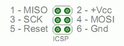
Note that the MOSI, MISO, and SCK pins are also at a consistent physical location on the 6-pin ICSP header:
To control MAX7219 displays you only need to make three connections:
- MOSI (Master Out Slave In) connected to DIN – The Master line sending data to the peripherals.
- SCK (Serial Clock) connected to CLK – The clock pulses which synchronize data transmission generated by the master.
- SS (Slave Select) connected to CS – The pin on each device that the master can use to enable and disable specific devices.
You can daisy chain multiple displays to create one large display by connecting DOUT of the first display to DIN of the next display. VCC, GND, CLK, and CS are shared between all of the displays.
You can select any of the digital pins of the Arduino for the SS/CS pin. Note that for this tutorial I used pin 3 (see table below).
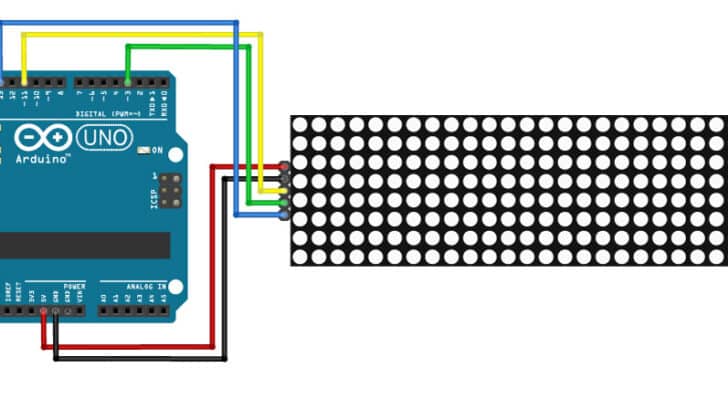
The wiring diagram below shows you how to connect the MAX7219 LED dot matrix display to the Arduino. Note that when using the MD_Parola library, you need to orient the display with the DIN connector on the right, otherwise the text will be printed upside down. For more information see the section below.
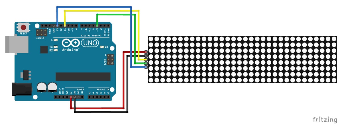
The connections are also given in the table below:
MAX7219 LED dot matrix display connections
| MAX7219 Display | Arduino |
|---|---|
| VCC | 5 V |
| GND | GND |
| DIN | 11 (MOSI) |
| CS | 3 (SS) |
| CLK | 13 (SCK) |
If you want to use software SPI instead, you can connect DIN, CS, and CLK to any of the digital pins of the Arduino. You just need to specify the pin numbers in the setup of the Arduino code (see examples below).
Power requirements
The maximum power that the Arduino Uno can safely deliver when powered from USB is around 400 mA at 5 V. If you want to control a large display it is therefore advised to use an external power supply.
Installing the MD_Parola and MD_MAX72XX Arduino libraries
To control the MAX7219 display we will be using two awesome Arduino libraries created by Marco Colli from MajicDesigns. The MD_Parola library can be used to create many different text animations like scrolling and sprite text effects. This library depends on the MD_MAX72XX library which implements the hardware functions of the LED matrix.
This are some functions and features of the library:
- Left, right, or center text justification
- Text scrolling with entry and exit effects
- Control display parameters and animation speed
- Multiple virtual displays (zones) in each string of LED modules
- Support for hardware SPI interface
- User-defined fonts and/or individual characters substitutions
- Support for double-height displays
- Support for mixing text and graphics on the same display
Marco has been working on this library for several years and has written some excellent tutorials on his blog. The source code and documentation for the libraries can be found here:
- MD_Parola source code on GitHub
- MD_Parola documentation
- MD_MAX72XX source code on GitHub
- MD_MAX72XX documentation
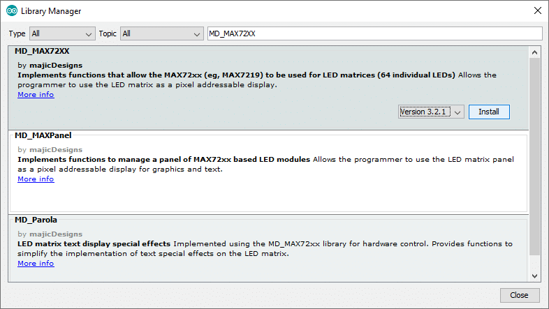
You can install the libraries via the Library Manager of the Arduino IDE. Go to Tools > Manage Libraries… or type Ctrl + Shift + I on Windows. The Library Manager will open and update the list of installed libraries.
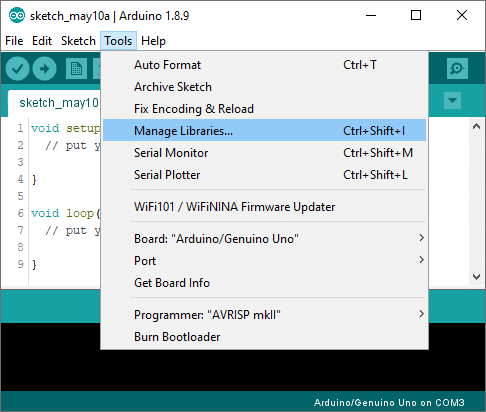
Search for ‘MD_MAX72XX’ and look for the libraries by majicDesigns. Select the latest version and then click install. Make sure that you install both the MD_MAX72XX library and the MD_Parola library.
Different types of LED dot matrix displays
Many different types and sizes of MAX7219 LED dot matrix displays are available on the market. The MD_MAX72XX library supports almost all of these displays but you need to configure the library correctly for the type of matrix being used.
Below you can find information about connecting and configuring the most common MAX7219 LED dot matrix displays that you can buy on Amazon, AliExpress, and eBay.
FC-16 8×8 or 8×32 module
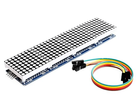
This is probably the most common MAX7219 display that you can find. It typically comes as either an 8×8 or 8×32 LED matrix and you can buy them with different colors of LEDs.
Module orientation and connections
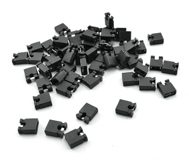
You can easily connect multiple 8×8 or 8×32 modules together to create one larger display. I typically solder straight male headers on the back of the modules and connect them together using jumpers. This way you can take them apart without having to desolder any connections.
The display is oriented with the DIN side on the right. Note that the screen-printed text on the back of the PCB might be upside down in this orientation.
           DP A  B  C  D  E  F  G
         +------------------------+
         | 7  6  5  4  3  2  1  0 | D0
 CLK <---|                      1 | D1 <--- CLK
  CS <---|                      2 | D2 <--- CS
DOUT <---|                      3 | D3 <--- DIN
 GND ----|                   O  4 | D4 ---- GND
 VCC ----|                O  O  5 | D5 ---- VCC
         |             O  O  O  6 | D6
         |          O  O  O  O  7 | D7
         +------------------------+
Hardware configuration in Arduino code
When setting up the display in your Arduino code you need to set the HARDWARE_TYPE to FC16_HW and specify the number of devices you have connected. An 8×8 matrix counts as 1 device, so if you want to control an 8×32 module you need to set MAX_DEVICES to 4 (an 8×32 display contains 4 MAX7219 ICs).
// Hardware SPI:
#define HARDWARE_TYPE MD_MAX72XX::FC16_HW
#define MAX_DEVICES 4
#define CS_PIN 2

// Create a new instance of the MD_MAX72XX class:
MD_Parola matrix = MD_Parola(HARDWARE_TYPE, CS_PIN, MAX_DEVICES);

// For software SPI you also need to specify the DATA_PIN and the CLK_PIN connections:
// #define DATA_PIN 3
// #define CLK_PIN 4

// Create a new instance of the MD_MAX72XX class:
// MD_Parola matrix = MD_Parola(HARDWARE_TYPE, DATA_PIN, CLK_PIN, CS_PIN, MAX_DEVICES);
Generic 8×8 module
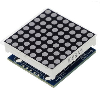
This is an 8×8 module mounted on a green PCB with the MAX7219 IC below the LED matrix. They are characterized by the 5-pin connectors at the short ends of the rectangular PCB.
Module orientation and connections
The generic module needs to be oriented with the MAX7219 IC at the top. You can connect multiple modules together with some short female to female jumper wires. Simply connect all the pins of the DOUT side of the first module to the DIN side of the next module.
      C  C  D  G  V
      L  S  I  N  C
      K     N  D  C
      |  |  |  |  |
      V  V  V  |  |
  D7 D6 D5 D4 D3 D2 D1 D0
+------------------------+
| 7  6  5  4  3  2  1  0 | DP
|                      1 | A
|                      2 | B
|                      3 | C
| O                    4 | D
| O  O                 5 | E
| O  O  O              6 | F
| O  O  O  O           7 | G
+------------------------+
      |  |  |  |  |
      V  V  V  |  |
      C  C  D  G  V
      L  S  O  N  C
      K     U  D  C
            T
Hardware configuration in Arduino code
For the generic display modules, you need to set the HARDWARE_TYPE to GENERIC_HW. The rest of the setup and MAX_DEVICES is the same as for the FC-16 modules.
// Hardware SPI:
#define HARDWARE_TYPE MD_MAX72XX::GENERIC_HW
#define MAX_DEVICES 1
#define CS_PIN 2

// Create a new instance of the MD_MAX72XX class:
MD_Parola matrix = MD_Parola(HARDWARE_TYPE, CS_PIN, MAX_DEVICES);

// For software SPI you also need to specify the DATA_PIN and the CLK_PIN connections:
// #define DATA_PIN 3
// #define CLK_PIN 4

// Create a new instance of the MD_MAX72XX class:
// MD_Parola matrix = MD_Parola(HARDWARE_TYPE, DATA_PIN, CLK_PIN, CS_PIN, MAX_DEVICES);
Arduino example codes
Below you will find several example codes that cover the basic functions of the MD_Parola Arduino library. After each example I explain how the code works so you should be able to modify it to suit your needs. You can also find more examples when you go to File > Examples > MD_Parola in the Arduino IDE, but they don't include any explanation so they might be a bit hard to follow.
Basic Arduino example code to print text
With the example code below you can print text on the display without any animations.
You can upload the example code to your Arduino via the Arduino IDE. For this tutorial, I used this standard 8x32 LED dot matrix display but you can use other types and/or sizes as well (see code explanation below).
/* Basic example code for MAX7219 LED dot matrix display
  with Arduino. More info: https://www.makerguides.com */

#include "MD_Parola.h"
#include "MD_MAX72xx.h"
#include "SPI.h"

// Define hardware type, size, and output pins:
#define HARDWARE_TYPE MD_MAX72XX::FC16_HW
#define MAX_DEVICES 4
#define CS_PIN 3

// Create a new instance of the MD_Parola class with hardware SPI connection:
MD_Parola myDisplay = MD_Parola(HARDWARE_TYPE, CS_PIN, MAX_DEVICES);

// Setup for software SPI:
// #define DATAPIN 2
// #define CLK_PIN 4
// MD_Parola myDisplay = MD_Parola(HARDWARE_TYPE, DATA_PIN, CLK_PIN, CS_PIN, MAX_DEVICES);

void setup() {
  // Intialize the object:
  myDisplay.begin();
  // Set the intensity (brightness) of the display (0-15):
  myDisplay.setIntensity(0);
  // Clear the display:
  myDisplay.displayClear();
}

void loop() {
  myDisplay.setTextAlignment(PA_CENTER);
  myDisplay.print("Center");
  delay(2000);
  myDisplay.setTextAlignment(PA_LEFT);
  myDisplay.print("Left");
  delay(2000);
  myDisplay.setTextAlignment(PA_RIGHT);
  myDisplay.print("Right");
  delay(2000);
  myDisplay.setTextAlignment(PA_CENTER);
  myDisplay.setInvert(true);
  myDisplay.print("Invert");
  delay(2000);
  myDisplay.setInvert(false);
  myDisplay.print(1234);
  delay(2000);
}
You should see the following output:

How the code works
The first step is to include all the required Arduino libraries. As I mentioned before, the MD_MAX72XX library implements the hardware functions of the LED matrix and the MD_Parola library the text effects. You will also need to include the SPI library, which comes pre-installed in the Arduino IDE. This library is used for the Serial Peripheral Interface communication between the display and the Arduino.
#include "MD_Parola.h"
#include "MD_MAX72xx.h"
#include "SPI.h"
Next, we need to specify which hardware we are using. Since I used a standard 8×32 display (also known as FC-16), I set the HARDWARE_TYPE to FC16_HW. The number of MAX7219 ICs in an 8×32 display is 4 so I set MAX_DEVICES to 4. Lastly, I defined to which pin the CS pin of the display is connected (output pin 3 in this case). See the section about display types for a more detailed explanation on how to set up other types of displays.
The statement #define is used to give a name to a constant value. The compiler will replace any references to this constant with the defined value when the program is compiled. So everywhere you mention CS_PIN, the compiler will replace it with the value 3 when the program is compiled.
// Define hardware type, size, and output pins:
#define HARDWARE_TYPE MD_MAX72XX::FC16_HW
#define MAX_DEVICES 4
#define CS_PIN 3
After this, a new instance of the MD_Parola class is created with the function MD_Parola(). This function needs three parameters, the first is the hardware type, the second the CS pin, and the third the number of max devices connected.
Note that I have called the MD_Parola object 'myDisplay' but you can use other names as well. You will need to change ‘myDisplay’ to the new name in the rest of the sketch.
When you want to use software SPI instead of hardware SPI, you also need to define the data and clock output pins and pass these as parameters when setting up the display object.
// Create a new instance of the MD_Parola class with hardware SPI connection:
MD_Parola myDisplay = MD_Parola(HARDWARE_TYPE, CS_PIN, MAX_DEVICES);

// Setup for software SPI:
// #define DATAPIN 2
// #define CLK_PIN 4
// MD_Parola myDisplay = MD_Parola(HARDWARE_TYPE, DATA_PIN, CLK_PIN, CS_PIN, MAX_DEVICES);
In the setup section of the code, we first initialize the object with the function begin(). The brightness of the display can be set with the function setIntensity(). You can enter a value between 0 (minimum brightness) and 15 (maximum brightness). The display is cleared with the function displayClear().
void setup() {
  // Intialize the object:
  myDisplay.begin();
  // Set the intensity (brightness) of the display (0-15):
  myDisplay.setIntensity(0);
  // Clear the display:
  myDisplay.displayClear();
}
In the loop section of the code, we first set the alignment of the text to be printed with the function setTextAlignment(). You can left, center, and right align the text with PA_LEFT, PA_CENTER, and PA_RIGHT respectively.
Next, the string ‘Center’ is printed with myDisplay.print("Center"). Note that you need to place quotation marks (” “) around the text since we are printing a text string. When you want to print numbers, no quotation marks are necessary. For example myDisplay.print(1234). You can invert the display, i.e. LEDs normally on turn off and vice versa, with myDisplay.setInvert(true).
void loop() {
  myDisplay.setTextAlignment(PA_CENTER);
  myDisplay.print("Center");
  delay(2000);
  myDisplay.setTextAlignment(PA_LEFT);
  myDisplay.print("Left");
  delay(2000);
  myDisplay.setTextAlignment(PA_RIGHT);
  myDisplay.print("Right");
  delay(2000);
  myDisplay.setTextAlignment(PA_CENTER);
  myDisplay.setInvert(true);
  myDisplay.print("Invert");
  delay(2000);
  myDisplay.setInvert(false);
  myDisplay.print(1234);
  delay(2000);
}
Scrolling text Arduino example code
When you want to print a message on a dot matrix display, you will often find that the display is too small to fit the entire message. The solution is in the MD_Parola library, which makes it super easy to create scrolling text effects. In the following examples, I will show you how to set this up, as well as how to use some of the other available text effects.
You can copy the code below by clicking on the button in the top right corner of the code field.
/* Example code for scrolling text effect on
   MAX7219 LED dot matrix display with Arduino.
   More info: https://www.makerguides.com */

#include "MD_Parola.h"
#include "MD_MAX72xx.h"
#include "SPI.h"

// Define hardware type, size, and output pins:
#define HARDWARE_TYPE MD_MAX72XX::FC16_HW
#define MAX_DEVICES 4
#define CS_PIN 3

// Create a new instance of the MD_Parola class with hardware SPI connection:
MD_Parola myDisplay = MD_Parola(HARDWARE_TYPE, CS_PIN, MAX_DEVICES);

// Setup for software SPI:
// #define DATA_PIN 2
// #define CLK_PIN 4
// MD_Parola myDisplay = MD_Parola(HARDWARE_TYPE, DATA_PIN, CLK_PIN, CS_PIN, MAX_DEVICES);

void setup() {
  // Intialize the object:
  myDisplay.begin();
  // Set the intensity (brightness) of the display (0-15):
  myDisplay.setIntensity(0);
  // Clear the display:
  myDisplay.displayClear();
  myDisplay.displayText("Scrolling text", PA_CENTER, 100, 0, PA_SCROLL_LEFT, PA_SCROLL_LEFT);
}

void loop() {
  if (myDisplay.displayAnimate()) {
    myDisplay.displayReset();
  }
}
How the code works
The first part of the code up to the end of the setup section is exactly the same as in the previous example. At the end of the setup section, we specify how we want to display the text with the function displayText(pText, align, speed, pause, effectIn, effectOut). This function takes 5 arguments.
The first parameter is the text string, in this case "Scrolling text".
The second argument sets the alignment of the text during the optional pause. You can use the same alignment options as in the previous example, i.e. PA_CENTER, PA_LEFT, or PA_RIGHT.
The third and fourth arguments set the speed of the animation and pause time respectively. The speed of the display is the time in milliseconds between animation frames. The lower this time the faster the animation. If you want to pause the text in between the in and out animation, you can set the pause time in milliseconds. I set it to zero so the text scrolls continuously.
Next, the in and out effects are specified. In this case I used PA_SCROLL_LEFT for both. See the example below for other text effects.
myDisplay.displayText("Scrolling text", PA_CENTER, 100, 0, PA_SCROLL_LEFT, PA_SCROLL_LEFT);
In the loop section, you only need two functions to create a scrolling text display.
First, we use the function displayAnimate() in an if statement. This function animates the display using the currently specified text and animation parameters and returns true when the animation has finished. When the animation has finished, we reset the display with the function displayReset() so the text is displayed in a loop.
void loop() {
  if (myDisplay.displayAnimate()) {
    myDisplay.displayReset();
  }
}
Other text effects
The library includes several other text effects that you can use:
- PA_PRINT,
- PA_SCAN_HORIZ,
- PA_SCROLL_LEFT,
- PA_WIPE,
- PA_SCROLL_UP_LEFT,
- PA_SCROLL_UP,
- PA_OPENING_CURSOR,
- PA_GROW_UP,
- PA_MESH,
- PA_SCROLL_UP_RIGHT,
- PA_BLINDS,
- PA_CLOSING,
- PA_RANDOM,
- PA_GROW_DOWN,
- PA_SCAN_VERT,
- PA_SCROLL_DOWN_LEFT,
- PA_WIPE_CURSOR,
- PA_DISSOLVE,
- PA_OPENING,
- PA_CLOSING_CURSOR,
- PA_SCROLL_DOWN_RIGHT,
- PA_SCROLL_RIGHT,
- PA_SLICE,
- PA_SCROLL_DOWN
The example code below steps through the different effect so you can see what they look like.
/*Example code for scrolling text and other text effects
  on MAX7219 LED dot matrix display with Arduino.
  More info: https://www.makerguides.com */

#include "MD_Parola.h"
#include "MD_MAX72xx.h"
#include "SPI.h"

int i = 0;

textEffect_t texteffect[] =
{
  PA_PRINT,
  PA_SCAN_HORIZ,
  PA_SCROLL_LEFT,
  PA_WIPE,
  PA_SCROLL_UP_LEFT,
  PA_SCROLL_UP,
  PA_OPENING_CURSOR,
  PA_GROW_UP,
  PA_MESH,
  PA_SCROLL_UP_RIGHT,
  PA_BLINDS,
  PA_CLOSING,
  PA_RANDOM,
  PA_GROW_DOWN,
  PA_SCAN_VERT,
  PA_SCROLL_DOWN_LEFT,
  PA_WIPE_CURSOR,
  PA_DISSOLVE,
  PA_OPENING,
  PA_CLOSING_CURSOR,
  PA_SCROLL_DOWN_RIGHT,
  PA_SCROLL_RIGHT,
  PA_SLICE,
  PA_SCROLL_DOWN
};

// Define hardware type, size, and output pins:
#define HARDWARE_TYPE MD_MAX72XX::FC16_HW
#define MAX_DEVICES 4
#define CS_PIN 3

// Create a new instance of the MD_Parola class with hardware SPI connection:
MD_Parola myDisplay = MD_Parola(HARDWARE_TYPE, CS_PIN, MAX_DEVICES);

// Setup for software SPI:
// #define DATA_PIN 2
// #define CLK_PIN 4
// MD_Parola myDisplay = MD_Parola(HARDWARE_TYPE, DATA_PIN, CLK_PIN, CS_PIN, MAX_DEVICES);

void setup() {
  myDisplay.begin();
  myDisplay.setIntensity(0);
  myDisplay.setTextAlignment(PA_CENTER);
  myDisplay.setPause(1000);
  myDisplay.setSpeed(100);
  myDisplay.displayClear();
}

void loop() {
  if (myDisplay.displayAnimate()) {
    if (i < sizeof(texteffect)) {
      i++;
    }
    else {
      i = 0;
    }
    myDisplay.displayText("Hello", myDisplay.getTextAlignment(),
                          myDisplay.getSpeed(), myDisplay.getPause(),
                          texteffect[i], texteffect[i]);
    myDisplay.displayReset();
  }
}
Text sprites
A relatively new function of the MD_Parola library is animated text sprites. In computer graphics, a sprite is a two-dimensional bitmap that is integrated into a larger scene (in this case, the matrix display).
A sprite is made up of a number of frames that run sequentially to make the animation on the display. Once the animation reaches the last frame it restarts from the first frame.
Note that I used an 8×64 matrix display for this example by connecting two 8×32 displays together (MAX_DEVICES is set to 8).
/*Example code for sprite text effect on
  MAX7219 LED dot matrix display with Arduino.
  More info: https://www.makerguides.com */

#include "MD_Parola.h"
#include "MD_MAX72xx.h"
#include "SPI.h"

// Define hardware type, size, and output pins:
#define HARDWARE_TYPE MD_MAX72XX::FC16_HW
#define MAX_DEVICES 8
#define CS_PIN 3

// Create a new instance of the MD_Parola class with hardware SPI connection:
MD_Parola myDisplay = MD_Parola(HARDWARE_TYPE, CS_PIN, MAX_DEVICES);

// Setup for software SPI:
// #define DATA_PIN 2
// #define CLK_PIN 4
// MD_Parola myDisplay = MD_Parola(HARDWARE_TYPE, DATA_PIN, CLK_PIN, CS_PIN, MAX_DEVICES);

// Sprite definitions:
const uint8_t F_PMAN1 = 6;
const uint8_t W_PMAN1 = 8;
const uint8_t PROGMEM pacman1[F_PMAN1 * W_PMAN1] =  // gobbling pacman animation
{
  0x00, 0x81, 0xc3, 0xe7, 0xff, 0x7e, 0x7e, 0x3c,
  0x00, 0x42, 0xe7, 0xe7, 0xff, 0xff, 0x7e, 0x3c,
  0x24, 0x66, 0xe7, 0xff, 0xff, 0xff, 0x7e, 0x3c,
  0x3c, 0x7e, 0xff, 0xff, 0xff, 0xff, 0x7e, 0x3c,
  0x24, 0x66, 0xe7, 0xff, 0xff, 0xff, 0x7e, 0x3c,
  0x00, 0x42, 0xe7, 0xe7, 0xff, 0xff, 0x7e, 0x3c,
};

const uint8_t F_PMAN2 = 6;
const uint8_t W_PMAN2 = 18;
const uint8_t PROGMEM pacman2[F_PMAN2 * W_PMAN2] =  // pacman pursued by a ghost
{
  0x00, 0x81, 0xc3, 0xe7, 0xff, 0x7e, 0x7e, 0x3c, 0x00, 0x00, 0x00, 0xfe, 0x7b, 0xf3, 0x7f, 0xfb, 0x73, 0xfe,
  0x00, 0x42, 0xe7, 0xe7, 0xff, 0xff, 0x7e, 0x3c, 0x00, 0x00, 0x00, 0xfe, 0x7b, 0xf3, 0x7f, 0xfb, 0x73, 0xfe,
  0x24, 0x66, 0xe7, 0xff, 0xff, 0xff, 0x7e, 0x3c, 0x00, 0x00, 0x00, 0xfe, 0x7b, 0xf3, 0x7f, 0xfb, 0x73, 0xfe,
  0x3c, 0x7e, 0xff, 0xff, 0xff, 0xff, 0x7e, 0x3c, 0x00, 0x00, 0x00, 0xfe, 0x7b, 0xf3, 0x7f, 0xfb, 0x73, 0xfe,
  0x24, 0x66, 0xe7, 0xff, 0xff, 0xff, 0x7e, 0x3c, 0x00, 0x00, 0x00, 0xfe, 0x7b, 0xf3, 0x7f, 0xfb, 0x73, 0xfe,
  0x00, 0x42, 0xe7, 0xe7, 0xff, 0xff, 0x7e, 0x3c, 0x00, 0x00, 0x00, 0xfe, 0x7b, 0xf3, 0x7f, 0xfb, 0x73, 0xfe,
};

const uint8_t F_WAVE = 14;
const uint8_t W_WAVE = 14;
const uint8_t PROGMEM wave[F_WAVE * W_WAVE] =  // triangular wave / worm
{
  0x08, 0x04, 0x02, 0x01, 0x02, 0x04, 0x08, 0x10, 0x20, 0x40, 0x80, 0x40, 0x20, 0x10,
  0x10, 0x08, 0x04, 0x02, 0x01, 0x02, 0x04, 0x08, 0x10, 0x20, 0x40, 0x80, 0x40, 0x20,
  0x20, 0x10, 0x08, 0x04, 0x02, 0x01, 0x02, 0x04, 0x08, 0x10, 0x20, 0x40, 0x80, 0x40,
  0x40, 0x20, 0x10, 0x08, 0x04, 0x02, 0x01, 0x02, 0x04, 0x08, 0x10, 0x20, 0x40, 0x80,
  0x80, 0x40, 0x20, 0x10, 0x08, 0x04, 0x02, 0x01, 0x02, 0x04, 0x08, 0x10, 0x20, 0x40,
  0x40, 0x80, 0x40, 0x20, 0x10, 0x08, 0x04, 0x02, 0x01, 0x02, 0x04, 0x08, 0x10, 0x20,
  0x20, 0x40, 0x80, 0x40, 0x20, 0x10, 0x08, 0x04, 0x02, 0x01, 0x02, 0x04, 0x08, 0x10,
  0x10, 0x20, 0x40, 0x80, 0x40, 0x20, 0x10, 0x08, 0x04, 0x02, 0x01, 0x02, 0x04, 0x08,
  0x08, 0x10, 0x20, 0x40, 0x80, 0x40, 0x20, 0x10, 0x08, 0x04, 0x02, 0x01, 0x02, 0x04,
  0x04, 0x08, 0x10, 0x20, 0x40, 0x80, 0x40, 0x20, 0x10, 0x08, 0x04, 0x02, 0x01, 0x02,
  0x02, 0x04, 0x08, 0x10, 0x20, 0x40, 0x80, 0x40, 0x20, 0x10, 0x08, 0x04, 0x02, 0x01,
  0x01, 0x02, 0x04, 0x08, 0x10, 0x20, 0x40, 0x80, 0x40, 0x20, 0x10, 0x08, 0x04, 0x02,
  0x02, 0x01, 0x02, 0x04, 0x08, 0x10, 0x20, 0x40, 0x80, 0x40, 0x20, 0x10, 0x08, 0x04,
  0x04, 0x02, 0x01, 0x02, 0x04, 0x08, 0x10, 0x20, 0x40, 0x80, 0x40, 0x20, 0x10, 0x08,
};

const uint8_t F_ROLL1 = 4;
const uint8_t W_ROLL1 = 8;
const uint8_t PROGMEM roll1[F_ROLL1 * W_ROLL1] =  // rolling square
{
  0xff, 0x8f, 0x8f, 0x8f, 0x81, 0x81, 0x81, 0xff,
  0xff, 0xf1, 0xf1, 0xf1, 0x81, 0x81, 0x81, 0xff,
  0xff, 0x81, 0x81, 0x81, 0xf1, 0xf1, 0xf1, 0xff,
  0xff, 0x81, 0x81, 0x81, 0x8f, 0x8f, 0x8f, 0xff,
};

const uint8_t F_ROLL2 = 4;
const uint8_t W_ROLL2 = 8;
const uint8_t PROGMEM roll2[F_ROLL2 * W_ROLL2] =  // rolling octagon
{
  0x3c, 0x4e, 0x8f, 0x8f, 0x81, 0x81, 0x42, 0x3c,
  0x3c, 0x72, 0xf1, 0xf1, 0x81, 0x81, 0x42, 0x3c,
  0x3c, 0x42, 0x81, 0x81, 0xf1, 0xf1, 0x72, 0x3c,
  0x3c, 0x42, 0x81, 0x81, 0x8f, 0x8f, 0x4e, 0x3c,
};

const uint8_t F_LINES = 3;
const uint8_t W_LINES = 8;
const uint8_t PROGMEM lines[F_LINES * W_LINES] =  // spaced lines
{
  0xff, 0xff, 0xff, 0x00, 0x00, 0xff, 0x00, 0x00,
  0xff, 0xff, 0x00, 0xff, 0x00, 0x00, 0xff, 0x00,
  0xff, 0xff, 0x00, 0x00, 0xff, 0x00, 0x00, 0xff,
};

const uint8_t F_ARROW1 = 3;
const uint8_t W_ARROW1 = 10;
const uint8_t PROGMEM arrow1[F_ARROW1 * W_ARROW1] =  // arrow fading to center
{
  0x18, 0x3c, 0x7e, 0xff, 0x7e, 0x00, 0x00, 0x3c, 0x00, 0x00,
  0x18, 0x3c, 0x7e, 0xff, 0x00, 0x7e, 0x00, 0x00, 0x18, 0x00,
  0x18, 0x3c, 0x7e, 0xff, 0x00, 0x00, 0x3c, 0x00, 0x00, 0x18,
};

const uint8_t F_ARROW2 = 3;
const uint8_t W_ARROW2 = 9;
const uint8_t PROGMEM arrow2[F_ARROW2 * W_ARROW2] =  // arrow fading to outside
{
  0x18, 0x3c, 0x7e, 0xe7, 0x00, 0x00, 0xc3, 0x00, 0x00,
  0x18, 0x3c, 0x7e, 0xe7, 0xe7, 0x00, 0x00, 0x81, 0x00,
  0x18, 0x3c, 0x7e, 0xe7, 0x00, 0xc3, 0x00, 0x00, 0x81,
};

const uint8_t F_SAILBOAT = 1;
const uint8_t W_SAILBOAT = 11;
const uint8_t PROGMEM sailboat[F_SAILBOAT * W_SAILBOAT] =  // sail boat
{
  0x10, 0x30, 0x58, 0x94, 0x92, 0x9f, 0x92, 0x94, 0x98, 0x50, 0x30,
};

const uint8_t F_STEAMBOAT = 2;
const uint8_t W_STEAMBOAT = 11;
const uint8_t PROGMEM steamboat[F_STEAMBOAT * W_STEAMBOAT] =  // steam boat
{
  0x10, 0x30, 0x50, 0x9c, 0x9e, 0x90, 0x91, 0x9c, 0x9d, 0x90, 0x71,
  0x10, 0x30, 0x50, 0x9c, 0x9c, 0x91, 0x90, 0x9d, 0x9e, 0x91, 0x70,
};

const uint8_t F_HEART = 5;
const uint8_t W_HEART = 9;
const uint8_t PROGMEM heart[F_HEART * W_HEART] =  // beating heart
{
  0x0e, 0x11, 0x21, 0x42, 0x84, 0x42, 0x21, 0x11, 0x0e,
  0x0e, 0x1f, 0x33, 0x66, 0xcc, 0x66, 0x33, 0x1f, 0x0e,
  0x0e, 0x1f, 0x3f, 0x7e, 0xfc, 0x7e, 0x3f, 0x1f, 0x0e,
  0x0e, 0x1f, 0x33, 0x66, 0xcc, 0x66, 0x33, 0x1f, 0x0e,
  0x0e, 0x11, 0x21, 0x42, 0x84, 0x42, 0x21, 0x11, 0x0e,
};

const uint8_t F_INVADER = 2;
const uint8_t W_INVADER = 10;
const uint8_t PROGMEM invader[F_INVADER * W_INVADER] =  // space invader
{
  0x0e, 0x98, 0x7d, 0x36, 0x3c, 0x3c, 0x36, 0x7d, 0x98, 0x0e,
  0x70, 0x18, 0x7d, 0xb6, 0x3c, 0x3c, 0xb6, 0x7d, 0x18, 0x70,
};

const uint8_t F_ROCKET = 2;
const uint8_t W_ROCKET = 11;
const uint8_t PROGMEM rocket[F_ROCKET * W_ROCKET] =  // rocket
{
  0x18, 0x24, 0x42, 0x81, 0x99, 0x18, 0x99, 0x18, 0xa5, 0x5a, 0x81,
  0x18, 0x24, 0x42, 0x81, 0x18, 0x99, 0x18, 0x99, 0x24, 0x42, 0x99,
};

const uint8_t F_FBALL = 2;
const uint8_t W_FBALL = 11;
const uint8_t PROGMEM fireball[F_FBALL * W_FBALL] =  // fireball
{
  0x7e, 0xab, 0x54, 0x28, 0x52, 0x24, 0x40, 0x18, 0x04, 0x10, 0x08,
  0x7e, 0xd5, 0x2a, 0x14, 0x24, 0x0a, 0x30, 0x04, 0x28, 0x08, 0x10,
};

const uint8_t F_CHEVRON = 1;
const uint8_t W_CHEVRON = 9;
const uint8_t PROGMEM chevron[F_CHEVRON * W_CHEVRON] =  // chevron
{
  0x18, 0x3c, 0x66, 0xc3, 0x99, 0x3c, 0x66, 0xc3, 0x81,
};

const uint8_t F_WALKER = 5;
const uint8_t W_WALKER = 7;
const uint8_t PROGMEM walker[F_WALKER * W_WALKER] =  // walking man
{
  0x00, 0x48, 0x77, 0x1f, 0x1c, 0x94, 0x68,
  0x00, 0x90, 0xee, 0x3e, 0x38, 0x28, 0xd0,
  0x00, 0x00, 0xae, 0xfe, 0x38, 0x28, 0x40,
  0x00, 0x00, 0x2e, 0xbe, 0xf8, 0x00, 0x00,
  0x00, 0x10, 0x6e, 0x3e, 0xb8, 0xe8, 0x00,
};

void setup() {
  myDisplay.begin();
  myDisplay.setIntensity(0);
  myDisplay.displayClear();
  myDisplay.setSpriteData(pacman2, W_PMAN2, F_PMAN2, pacman2, W_PMAN2, F_PMAN2);
  myDisplay.displayText("Parola sprites", PA_CENTER, 50, 1000, PA_SPRITE, PA_SPRITE);
}

void loop() {
  if (myDisplay.displayAnimate()) {
    myDisplay.displayReset();
  }
}
How the code works
After setting up the display like before, the text sprites are defined.
Two constants are used to define the sprite, one for the width (number of bytes) data for one sprite and the other for the number of frames contained in the animation. The total number of bytes required is the width * number of frames. Note that the sprite data is stored in PROGMEM to save RAM space.
Each row of the array is made up of hexadecimal numbers that set which LEDs need to light up in each column of the sprite.
The example includes many different sprite definitions, which you can also find in one of the examples that come with the library.
// Sprite definitions:
const uint8_t F_PMAN1 = 6;
const uint8_t W_PMAN1 = 8;
const uint8_t PROGMEM pacman1[F_PMAN1 * W_PMAN1] =  // gobbling pacman animation
{
  0x00, 0x81, 0xc3, 0xe7, 0xff, 0x7e, 0x7e, 0x3c,
  0x00, 0x42, 0xe7, 0xe7, 0xff, 0xff, 0x7e, 0x3c,
  0x24, 0x66, 0xe7, 0xff, 0xff, 0xff, 0x7e, 0x3c,
  0x3c, 0x7e, 0xff, 0xff, 0xff, 0xff, 0x7e, 0x3c,
  0x24, 0x66, 0xe7, 0xff, 0xff, 0xff, 0x7e, 0x3c,
  0x00, 0x42, 0xe7, 0xe7, 0xff, 0xff, 0x7e, 0x3c,
};
In the setup, the function setSpriteData(inData, inWidth, inFrames, outData, outWidth, outFrames) is used to set up user data needed so that the library can display the sprite when the PA_SPRITE animation type is selected in the displayText() function.
You can select any of the predefined sprites, in this case I used pacman2 (pacman pursued by a ghost).
  myDisplay.setSpriteData(pacman2, W_PMAN2, F_PMAN2, pacman2, W_PMAN2, F_PMAN2);
  myDisplay.displayText("Parola sprites", PA_CENTER, 50, 1000, PA_SPRITE, PA_SPRITE);
The loop section is the same as before.
Conclusion
In this article, I have shown you how you can use a MAX7219 LED dot matrix display with Arduino. We looked at the basics of printing text, scrolling text, other text effects, and text sprites. There still are some less frequently used functions in the MD_Parola library that I haven't covered in this tutorial but you can check those out in the MD_Parola documentation on GitHub.
I hope you found this tutorial useful and informative. If you did, please share it with a friend who also likes electronics and making things!
I would love to know what projects you plan on building (or have already built) with this display. If you have any questions, suggestions, or if you think that things are missing in this tutorial, please leave a comment down below.
Note that comments are held for moderation to prevent spam.

This work is licensed under a Creative Commons Attribution-NonCommercial-ShareAlike 4.0 International License.
Other Useful Links From Around The Web:
Benne is professional Systems Engineer with a deep expertise in Arduino and a passion for DIY projects.
Glen Lewis
Monday 11th of December 2023
Hi Guys I am using “MAX7219 LED dot 8x8 matrix display Arduino” x 8 Is it possible to have 2 x (separate) pieces of data displayed at the same time? its for a scoreboard so score 1 displayed Left justified and score 2 displayed Right justified (at the same time). I have already built the scoreboard and now I want to display the final info to a larger scoreboard through a Bluetooth connection (Serial) as I plan to run it through Bluetooth i don't think I could use 2 separate 8x8x4 displays?? any pointers and coding help would be greatly appreciated Kind regards Glen
Siggi.M
Friday 29th of March 2024
@Stefan Maetschke, Hallo Stefan, vielen Dank für die super schnelle Antwort. Die Tips sind große Klasse. Ich werde das ausprobieren und bei Erfolg Dir schreiben. Viele Grüße Siggi
Siggi.M
Thursday 28th of March 2024
@Stefan Maetschke, Hallo Stefan, ich habe mein Programm fertig. Die 8x32 LED-Matrix und das ESP32 Modul ist in einem LGB-Wagen (selbst kreiert) eingebaut. Die Steuerung erfolgt über Infrarot mit einer Infrarotfernbedienung. Damit kann ich die verschiedenen Animationen anzeigen lassen. Dabei ist auch eine Temperaturanzeige mit dem DHT11 . Insgesamt 8 Animationen plus Temperatur und ein "default" -Wert. Alles funktioniert einwandfrei. Ein Video vom LGB-Wagen könnte ich Dir schicken, wenn ich Deine email-Adresse hätte.
Nun habe ich eine Frage zur "loop"-Schleife. Wie kann ich mehrere Animationen automatisch nacheinander ablaufen lassen (also ohne Infrarotauswahl)? Hast Du vielleicht einen Tip?
Hier mein jetziger code: Vielleicht gibt es hier noch eine Vereinfachung? Danke schon mal im voraus und ein schönes Osterfest.
/* Laufschrift+Animation für LGB-INFO Wagen Hardware: ESP32-WROOM-DA Modul, DHT11, IR-VS1838 LED-Matrix 8x32 (4x(8x8)) Infrarotbedienung ESP32-WROOM-DA-Module 24.03.2024 - SiggiMu*/
#include #include #include #include //============================= #include #include //============================= // Define hardware type, size, and output pins: #define HARDWARE_TYPE MD_MAX72XX::FC16_HW #define MAX_DEVICES 4 // Setup for software SPI: #define CS_PIN 15 #define DATA_PIN 23 #define CLK_PIN 18 #define delay_t 50 // in milliseconds //======für Temperaturanzeige================================ #define SPEED_TIME 75 // Speed of the transition #define PAUSE_TIME 0 #define MAX_MESG 20 #define DHTPIN 25 // These are for the temperature6 #define DHTTYPE DHT11 #define TIMEDHT 1000 //------für Temperaturanzeige---------------------------------------------------------- char szTime[9]; // mm:ss\0 char szMesg[MAX_MESG + 1] = ""; float celsius; uint8_t degC[] = { 6, 3, 3, 56, 68, 68, 68 }; // Deg C uint8_t clear = 0x00; uint32_t timerDHT = TIMEDHT; DHT dht(DHTPIN, DHTTYPE); uint8_t decToBcd(uint8_t value) {return ((value / 10 * 16) + (value % 10));} //======Infrarot und extra LED================================ const int RECV_PIN = 36; IRrecv irrecv(RECV_PIN); decode_results results; int ircode = 0; int ircodex = 0; const int bluePin = 2; bool LEDstatus=false; //============================================================ MD_MAX72XX mx = MD_MAX72XX(HARDWARE_TYPE, DATA_PIN, CLK_PIN, CS_PIN, MAX_DEVICES); MD_Parola myDisplay = MD_Parola(HARDWARE_TYPE, DATA_PIN, CLK_PIN, CS_PIN, MAX_DEVICES); MD_Parola myDisplay0 = MD_Parola(HARDWARE_TYPE, DATA_PIN, CLK_PIN, CS_PIN, MAX_DEVICES); MD_Parola myDisplay1 = MD_Parola(HARDWARE_TYPE, DATA_PIN, CLK_PIN, CS_PIN, MAX_DEVICES); MD_Parola myDisplay2 = MD_Parola(HARDWARE_TYPE, DATA_PIN, CLK_PIN, CS_PIN, MAX_DEVICES); MD_Parola myDisplay3 = MD_Parola(HARDWARE_TYPE, DATA_PIN, CLK_PIN, CS_PIN, MAX_DEVICES); MD_Parola myDisplay4 = MD_Parola(HARDWARE_TYPE, DATA_PIN, CLK_PIN, CS_PIN, MAX_DEVICES); MD_Parola myDisplay5 = MD_Parola(HARDWARE_TYPE, DATA_PIN, CLK_PIN, CS_PIN, MAX_DEVICES); MD_Parola myDisplay6 = MD_Parola(HARDWARE_TYPE, DATA_PIN, CLK_PIN, CS_PIN, MAX_DEVICES); MD_Parola myDisplay8 = MD_Parola(HARDWARE_TYPE, DATA_PIN, CLK_PIN, CS_PIN, MAX_DEVICES); MD_Parola myDisplay9 = MD_Parola(HARDWARE_TYPE, DATA_PIN, CLK_PIN, CS_PIN, MAX_DEVICES); //=======Static-Bilder face=Smiley arrow=Pfeil================= byte herz[8] = {0xc6, 0x129, 0x111, 0x101, 0x82, 0x44, 0x28, 0x10}; byte face[8] = {0x3C, 0x42, 0xA5, 0x81, 0xA5, 0x99, 0x42, 0x3C}; byte face2[8] = {0x00, 0x24, 0x24, 0x24, 0x00, 0x42, 0x3C, 0x00}; byte arrow[8] = {0x18, 0x0C, 0x06, 0xFF, 0xFF, 0x06, 0x0C, 0x18}; byte leerz[8] = {0x00, 0x00, 0x00, 0x00, 0x00, 0x00, 0x00, 0x00}; //=========================================================== const uint8_t F_LOK = 5; const uint8_t W_LOK = 32; const uint8_t PROGMEM lok[F_LOK * W_LOK] = // Lokomotive, Wagen, 2 Walker { 0x78, 0xcc, 0xcb, 0x48, 0x4f, 0xc9, 0xc9, 0x7f, 0x20, 0x7f, 0xc9, 0xc9, 0x4f, 0x49, 0xcf, 0xc9, 0x7f, 0x00, 0x48, 0x77, 0x1f, 0x1c, 0x94, 0x68, 0x00, 0x48, 0x77, 0x1f, 0x1c, 0x94, 0x68, 0x00, 0x78, 0xcc, 0xcb, 0x48, 0x4f, 0xc9, 0xc9, 0x7f, 0x20, 0x7f, 0xc9, 0xc9, 0x4f, 0x49, 0xcf, 0xc9, 0x7f, 0x00, 0x90, 0xee, 0x3e, 0x38, 0x28, 0xd0, 0x00, 0x90, 0xee, 0x3e, 0x38, 0x28, 0xd0, 0x00, 0x78, 0x48, 0x8a, 0x48, 0x4f, 0x49, 0x89, 0x7f, 0x20, 0x7f, 0xc9, 0xc9, 0x4f, 0x49, 0xcf, 0xc9, 0x7f, 0x00, 0xae, 0xfe, 0x38, 0x28, 0x40, 0x00, 0x00, 0xae, 0xfe, 0x38, 0x28, 0x40, 0x00, 0x00, 0x78, 0xcc, 0xcb, 0x48, 0x4f, 0xc9, 0xc9, 0x7f, 0x20, 0x7f, 0xc9, 0xc9, 0x4f, 0x49, 0xcf, 0xc9, 0x7f, 0x00, 0x00, 0x2e, 0xbe, 0xf8, 0x00, 0x00, 0x00, 0x2e, 0xbe, 0xf8, 0x00, 0x00, 0x00, 0x00, 0x00, 0x00, 0x00, 0x00, 0x00, 0x00, 0x00, 0x00, 0x00, 0x00, 0x00, 0x00, 0x00, 0x00, 0x00, 0x00, 0x00, 0x00, 0x10, 0x6e, 0x3e, 0xb8, 0xe8, 0x00, 0x00, 0x10, 0x6e, 0x3e, 0xb8, 0xe8, 0x00, 0x00, }; //=========================================================== const uint8_t F_WALKER = 5; const uint8_t W_WALKER = 19; const uint8_t PROGMEM walker[F_WALKER * W_WALKER] = // walking man, 2 Walker { 0x00, 0x48, 0x77, 0x1f, 0x1c, 0x94, 0x68, 0x00, 0x00, 0x00, 0x00, 0x00, 0x00, 0x48, 0x77, 0x1f, 0x1c, 0x94, 0x68, 0x00, 0x90, 0xee, 0x3e, 0x38, 0x28, 0xd0, 0x00, 0x00, 0x00, 0x00, 0x00, 0x00, 0x90, 0xee, 0x3e, 0x38, 0x28, 0xd0, 0x00, 0x00, 0xae, 0xfe, 0x38, 0x28, 0x40, 0x00, 0x00, 0x00, 0x00, 0x00, 0x00, 0x00, 0xae, 0xfe, 0x38, 0x28, 0x40, 0x00, 0x00, 0x2e, 0xbe, 0xf8, 0x00, 0x00, 0x00, 0x00, 0x00, 0x00, 0x00, 0x00, 0x00, 0x2e, 0xbe, 0xf8, 0x00, 0x00, 0x00, 0x00, 0x2e, 0xbe, 0xf8, 0x00, 0x00, 0x00, 0x00, 0x00, 0x00, 0x00, 0x00, 0x00, 0x00, 0x2e, 0xbe, 0xf8, 0x00, }; //============================================================ const uint8_t F_HEART = 5; const uint8_t W_HEART = 9; const uint8_t PROGMEM heart[F_HEART * W_HEART] = // beating heart { 0x0e, 0x11, 0x21, 0x42, 0x84, 0x42, 0x21, 0x11, 0x0e, 0x0e, 0x1f, 0x33, 0x66, 0xcc, 0x66, 0x33, 0x1f, 0x0e, 0x0e, 0x1f, 0x3f, 0x7e, 0xfc, 0x7e, 0x3f, 0x1f, 0x0e, 0x0e, 0x1f, 0x33, 0x66, 0xcc, 0x66, 0x33, 0x1f, 0x0e, 0x0e, 0x11, 0x21, 0x42, 0x84, 0x42, 0x21, 0x11, 0x0e, }; //============================================================ const uint8_t F_PMAN2 = 6; const uint8_t W_PMAN2 = 19; const uint8_t PROGMEM pacman2[F_PMAN2 * W_PMAN2] = // pacman pursued by a ghost { 0x00, 0x81, 0xc3, 0xe7, 0xff, 0x7e, 0x7e, 0x3c, 0x00, 0x00, 0x00, 0x00, 0xfe, 0x7b, 0xf3, 0x7f, 0xfb, 0x73, 0xfe, 0x00, 0x42, 0xe7, 0xe7, 0xff, 0xff, 0x7e, 0x3c, 0x00, 0x00, 0x00, 0x00, 0xfe, 0x7b, 0xf3, 0x7f, 0xfb, 0x73, 0xfe, 0x24, 0x66, 0xe7, 0xff, 0xff, 0xff, 0x7e, 0x3c, 0x00, 0x00, 0x00, 0x00, 0xfe, 0x7b, 0xf3, 0x7f, 0xfb, 0x73, 0xfe, 0x3c, 0x7e, 0xff, 0xff, 0xff, 0xff, 0x7e, 0x3c, 0x00, 0x00, 0x00, 0x00, 0xfe, 0x7b, 0xf3, 0x7f, 0xfb, 0x73, 0xfe, 0x24, 0x66, 0xe7, 0xff, 0xff, 0xff, 0x7e, 0x3c, 0x00, 0x00, 0x00, 0x00, 0xfe, 0x7b, 0xf3, 0x7f, 0xfb, 0x73, 0xfe, 0x00, 0x42, 0xe7, 0xe7, 0xff, 0xff, 0x7e, 0x3c, 0x00, 0x00, 0x00, 0x00, 0xfe, 0x7b, 0xf3, 0x7f, 0xfb, 0x73, 0xfe, }; //============================================================ const uint8_t F_ROCKET = 2; const uint8_t W_ROCKET = 11; const uint8_t PROGMEM rocket[F_ROCKET * W_ROCKET] = // rocket { 0x18, 0x24, 0x42, 0x81, 0x99, 0x18, 0x99, 0x18, 0xa5, 0x5a, 0x81, 0x18, 0x24, 0x42, 0x81, 0x18, 0x99, 0x18, 0x99, 0x24, 0x42, 0x99, }; // ========================================================== const uint8_t F_HASE = 2; const uint8_t W_HASE = 15; const uint8_t PROGMEM hase[F_HASE * W_HASE] = // hase { 0x00, 0x18, 0x34, 0xbe, 0xff, 0xfb, 0x78, 0xfc, 0xfc, 0xfc, 0xfc, 0x78, 0x30, 0x18, 0x00, 0x00, 0x0c, 0x1a, 0x5e, 0x7f, 0x7b, 0x79, 0xfc, 0xfc, 0xfc, 0xfc, 0x78, 0x70, 0x30, 0x00, }; // ========================================================== void setup() { //-------für Temperatur----------------------------------------------------------------------- Serial.begin(9600); dht.begin(); // initialize the DHT sensor
Wire.begin(); myDisplay9.begin(2); myDisplay9.setIntensity(2); myDisplay9.setInvert(false); myDisplay9.setZone(0, MAX_DEVICES - 4, MAX_DEVICES - 1); myDisplay9.displayZoneText(0, szMesg, PA_CENTER, SPEED_TIME, 0, PA_PRINT, PA_NO_EFFECT); myDisplay9.addChar('$', degC); dht.begin(); //---------------------------------------------------------------------------- irrecv.enableIRIn(); pinMode(bluePin, OUTPUT);
mx.begin(); mx.control(MD_MAX72XX::INTENSITY, 0); mx.clear(); //=================================================================================== myDisplay.begin(); myDisplay.setIntensity(2); myDisplay.displayClear(); myDisplay.displayText("Cool ", PA_CENTER, 100, 1000, PA_PRINT, PA_NO_EFFECT);
myDisplay0.begin(); myDisplay0.setIntensity(2); myDisplay0.displayClear(); myDisplay0.displayScroll("Push Taste", PA_CENTER, PA_SCROLL_LEFT, 100); //=================================================================================== myDisplay1.begin(); myDisplay1.setIntensity(2); myDisplay1.displayClear();
myDisplay2.begin(); myDisplay2.setIntensity(2); myDisplay2.displayClear();
myDisplay3.begin(); myDisplay3.setIntensity(2); myDisplay3.displayClear();
myDisplay4.begin(); myDisplay4.setIntensity(2); myDisplay4.displayClear();
myDisplay5.begin(); myDisplay5.setIntensity(2); myDisplay5.displayClear();
myDisplay6.begin(); myDisplay6.setIntensity(2); myDisplay6.displayClear();
myDisplay8.begin(); myDisplay8.setIntensity(2); myDisplay8.displayClear(); myDisplay8.displayText("Hallo ", PA_RIGHT, 100, 1000, PA_PRINT, PA_NO_EFFECT); // ("Text"", PA_CENTER, SCROLL_SPEED, PAUSE_TIME, PA_PRINT, PA_NO_EFFECT); //================================================================================
myDisplay1.setSpriteData(lok, W_LOK, F_LOK, lok, W_LOK, F_LOK); myDisplay1.displayText(" LGB ", PA_CENTER, 60, 4000, PA_SPRITE, PA_SPRITE);
myDisplay2.setSpriteData(walker, W_WALKER, F_WALKER, walker, W_WALKER, F_WALKER); myDisplay2.displayText(" Lauf! ", PA_CENTER, 60, 4000, PA_SPRITE, PA_SPRITE);
myDisplay3.setSpriteData(heart, W_HEART, F_HEART, heart, W_HEART, F_HEART); myDisplay3.displayText(" Herz ", PA_CENTER, 60, 4000, PA_SPRITE, PA_SPRITE);
myDisplay4.setSpriteData(pacman2, W_PMAN2, F_PMAN2, pacman2, W_PMAN2, F_PMAN2); myDisplay4.displayText(" Man? ", PA_CENTER, 60, 4000, PA_SPRITE, PA_SPRITE);
myDisplay5.setSpriteData(rocket, W_ROCKET, F_ROCKET, rocket, W_ROCKET, F_ROCKET); myDisplay5.displayText(" Rakete ", PA_CENTER, 60, 4000, PA_SPRITE, PA_SPRITE);
myDisplay6.setSpriteData(hase, W_HASE, F_HASE, hase, W_HASE, F_HASE); myDisplay6.displayText(" Ostern ", PA_CENTER, 60, 4000, PA_SPRITE, PA_SPRITE); } //======================================================================= void loop() { if (irrecv.decode(&results)){ irrecv.resume(); } ircode = (results.value); if (ircode == 16738455) {ircodex = 10 ;} //1 if (ircode == 16750695) {ircodex = 20 ;} //2 if (ircode == 16756815) {ircodex = 30 ;} //3 if (ircode == 16724175) {ircodex = 40 ;} //4 if (ircode == 16718055) {ircodex = 50 ;} //5 if (ircode == 16743045) {ircodex = 60 ;} //6 if (ircode == 16716015) {ircodex = 70 ;} //7 if (ircode == 16726215) {ircodex = 80 ;} //8 if (ircode == 16734885) {ircodex = 90 ;} //9 if (ircode == 16728765) {ircodex = 99 ;} //* if (ircode == 16730805) {ircodex = 100 ;} //0 if (ircode == 16732845) {ircodex = 110 ;} //# if (ircode == 16712445) {ircodex = 200 ;} //ok
switch(ircodex){ default: digitalWrite(bluePin, LOW); if (myDisplay0.displayAnimate()){ myDisplay0.displayReset();} delay(10); //ircodex = 10; break; case 10: digitalWrite(bluePin, HIGH); if (myDisplay1.displayAnimate()){ myDisplay1.displayReset();} break; case 20: digitalWrite(bluePin, HIGH); if (myDisplay2.displayAnimate()){ myDisplay2.displayReset();} break; case 30: digitalWrite(bluePin, HIGH); if (myDisplay3.displayAnimate()){ myDisplay3.displayReset();} break; case 40: digitalWrite(bluePin, HIGH); if (myDisplay4.displayAnimate()){ myDisplay4.displayReset();} break; case 50: digitalWrite(bluePin, HIGH); if (myDisplay5.displayAnimate()){ myDisplay5.displayReset();} break; case 60: digitalWrite(bluePin, HIGH); if (myDisplay6.displayAnimate()){ myDisplay6.displayReset();} break; case 80: digitalWrite(bluePin, LOW); myDisplay8.displayReset(); if (myDisplay8.displayAnimate()){ myDisplay8.displayReset();} delay(500); Zeichen2(); delay(2000); ircodex=100; break; case 99: digitalWrite(bluePin, HIGH); if (myDisplay8.displayAnimate()){ myDisplay8.displayReset();} delay(500); Zeichen2(); delay(3000); if (myDisplay.displayAnimate()){ myDisplay.displayReset();} delay(500); Zeichen12(); delay(3000); ircodex=100; break; case 110: digitalWrite(bluePin, LOW); myDisplay.displayReset(); if (myDisplay.displayAnimate()){ myDisplay.displayReset();} delay(500); Zeichen12(); delay(2000); ircodex = 100; break; case 100: digitalWrite(bluePin, LOW); myDisplay.displayClear(); myDisplay0.displayClear(); myDisplay1.displayClear(); myDisplay2.displayClear(); myDisplay3.displayClear(); myDisplay4.displayClear(); myDisplay5.displayClear(); myDisplay6.displayClear(); myDisplay8.displayClear(); myDisplay9.displayClear(); ircodex = 0; break; case 200: int i; for (int i=0;i<10;i++){ float tempC = dht.readTemperature(); Serial.println(tempC); tempC = (tempC-2); celsius = tempC; static uint32_t lastTime = 0; // Memory (ms) static uint8_t display = 0; // Current display mode static bool flasher = false; // Seconds passing flasher getTemperature(); myDisplay9.setIntensity(1); myDisplay9.displayAnimate(); myDisplay9.setPause(0, 1000); myDisplay9.setTextEffect(0, PA_NO_EFFECT, PA_NO_EFFECT); dtostrf(celsius, 3, 1, szMesg); strcat(szMesg, "$"); myDisplay9.displayReset(0); // Rest zone zero delay(2000); Serial.println (i); if (i == 8) { break; ircodex = 10; } break; } } } //=============Funktionen======================================================= void getTemperature() { if ((millis() - timerDHT) > TIMEDHT) { // Wait for a time between measurements timerDHT = millis(); // Update the timer celsius = dht.readTemperature(); } } //------------------------------------------------------------------------------ void Zeichen1() { for (int i = 0; i <= 7; i++) { mx.setRow(3, 3, i, herz[i]); //mx.setRow(0, 0, i, herz[i]); } delay(delay_t); } //------------------------------------------------------------------------------ void Zeichen2() { for (int i = 0; i <= 7; i++) { mx.setRow(3, 3, i, face[i]); //mx.setRow(1, 1, i, face[i]); } delay(delay_t); } //------------------------------------------------------------------------------ void Zeichen3() { for (int i = 0; i <= 7; i++) { mx.setRow(2, 2, i, face2[i]); } delay(delay_t); } //------------------------------------------------------------------------------ void Zeichen4() { for (int i = 0; i <= 7; i++) { mx.setRow(3, 3, i, arrow[i]); } delay(delay_t); } //------------------------------------------------------------------------------ void Zeichen11() { for (int i = 0; i <= 7; i++) { mx.setRow(3, 3, i, leerz[i]); } delay(delay_t); } //------------------------------------------------------------------------------ void Zeichen12() { for (int i = 0; i <= 7; i++) { mx.setRow(0, 0, i, face[i]); } delay(delay_t); } //------------------------------------------------------------------------------
Stefan Maetschke
Monday 18th of December 2023
It's a bit tricky to answer, but you probably want to avoid trying to "display 2 x (separate) pieces of data at the same time". The easiest way is probably to display the two data pieces together and do the left and right justification yourself.
Siggi.M
Monday 25th of September 2023
Hello, the tutorial "MAX7219 LED dot matrix display Arduino" It's great because everything is explained. All examples run on the Arduino Nano without any problems. Thanks for that. I have a question about the last example:
"Example code for sprite text effect on MAX7219 LED dot matrix display with Arduino." In the processing loop: void setup() { myDisplay.begin(); myDisplay.setIntensity(0); myDisplay.displayClear(); myDisplay.setSpriteData(pacman2, W_PMAN2, F_PMAN2, pacman2, W_PMAN2, F_PMAN2); myDisplay.displayText("Parola sprites", PA_CENTER, 50, 1000, PA_SPRITE, PA_SPRITE);}
I want instead of "myDisplay.displayText". "myDisplay.display... 2 graphic characters" Insert Can someone please help me how to do this?
I want to have a locomotive with wagons drive across the display and let the walker run behind it. Is for my garden railway. Thank you in advance Siggi
Jean-Marc
Friday 25th of August 2023
Forget my last comment, my Display is no I2C. I am definitively too old !!!!!!!! Greetings Jean-Marc
Jean-Marc
Friday 25th of August 2023
I think this library is exactly what i am looking for. Unfortunatly i have a I2c version of a 8x32 Display. Is there a way (other library ?) to use it. Now i use it with a other library. It works but this new library would have much more functionalities. In advance thanks a lot for your help. I started 2022 with Raspberry and arduino stuff. What a wonderful world. thanks a lot to all the makers for a lot of examples. I am 81 but still fully motivated Jean-Marc
Glen Lewis
Monday 11th of December 2023
@Jean-Marc, Electronics is in your blood - Keep going old mate :)
Rick Neal
Wednesday 22nd of March 2023
I like the way you explained the sketches as it was very helpful. I however, didn't understand how the sketch could work with just a CS lead. Pin #3. I was only able to get the sketches to work with line (14) disabled and lines (17-19) enabled. Maybe that's why it would work once and then had junk to display? Thanks, Rick