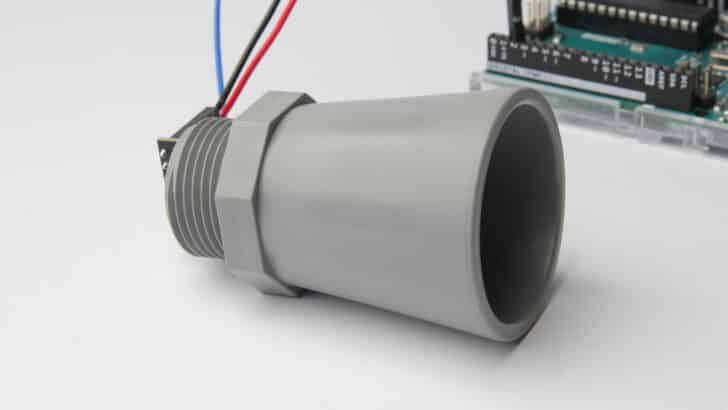
The MaxBotix MB7389 HRXL-MaxSonar-WR is a weather-resistant ultrasonic distance sensor with a range of 30 to 500 cm and a resolution of 1 mm. This sensor is ideal for outdoor applications such as water tank or bin level measurement. It has a very small beam angle and can also be used for robot applications. Although this tutorial is written for the MB7389, it can also be used for other MaxBotix sensors.
In this tutorial, you will learn how the sensor works and how you can use it with an Arduino. I have included 3 examples with wiring diagrams that show the basic operation of the sensor. We will look at the different outputs of the sensor and I will show you the difference between free-run mode and triggered mode.
After each example, I break down and explain how the code works, so you should have no problems modifying it to suit your needs.
If you have any questions, please leave a comment below.
If you would like to learn more about other distance sensors, then the articles below might be useful:
- Waterproof JSN-SR04T Ultrasonic Distance Sensor with Arduino Tutorial
- How to use a SHARP GP2Y0A21YK0F IR Distance Sensor with Arduino
- How to use a SHARP GP2Y0A710K0F IR Distance Sensor with Arduino
- How to use a HC-SR04 Ultrasonic Distance Sensor
Supplies
Hardware components
| MB7389-100 HRXL-MaxSonar-WRMT | × 1 | Amazon | |
| Arduino Uno Rev3 | × 1 | Amazon | |
| Breadboard | × 1 | Amazon | |
| Jumper wires | ~ 10 | Amazon | |
| Header pins (optional) | × 7 | Amazon | |
| Momentary push button | × 1 | Amazon | |
| USB cable type A/B | × 1 | Amazon |
Software
Makerguides.com is a participant in the Amazon Services LLC Associates Program, an affiliate advertising program designed to provide a means for sites to earn advertising fees by advertising and linking to products on Amazon.com. As an Amazon Associate we earn from qualifying purchases.
How does an ultrasonic sensor work?
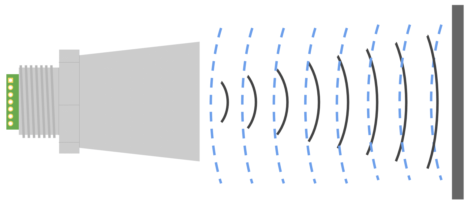
An ultrasonic distance sensor works by sending out ultrasound waves. These ultrasound waves get reflected by an object and the ultrasonic sensor detects them. By measuring how much time passed between sending and receiving the sound waves, you can calculate the distance between the sensor and the object.
Distance (cm) = Speed of sound (cm/µs) × Time (µs) / 2
Where Time is the time between sending and receiving the sound waves in microseconds. At 20 °C the speed of sound is roughly 343 m/s or 0.034 cm/µs.
Note that you need to divide the result by two. This is because the sound waves traveled from the sensor to the object and back from the object to the sensor. So the distance between the sensor and the object is only half the distance that the sound waves traveled.
For more information on how ultrasonic sensors work, you can check out my article on the HC-SR04. In this article, the working principles of an ultrasonic distance sensor are explained in greater detail.
Information about the sensor
The MaxBotix MB7389 HRXL-MaxSonar-WR is an ultrasonic distance sensor made by MaxBotix Inc. MaxBotix is a US based manufacturer that specializes in ultrasonic sensors. They make sensors for all kinds of applications, both for indoor and outdoor use.
MaxBotix does not call their sensors ‘waterproof’ but the sensors are properly tested and rated with an IP67 weather-resistance rating. You can find the definition of this rating here on Wikipedia.
What you might not know, is that the speed of sound strongly depends on the temperature and humidity of the air. The speed of sound in air increases about 0.6 meters per second, per degree centigrade. Unlike many other sensors, the MB7389 features on board internal temperature compensation. This means that the sensor will automatically compensate for the speed of sound changes and continue to give accurate readings. You can also install an external temperature sensor, for even more accurate temperature compensation.
More specifications of the sensor can be found in the table below.
MB7389 HRXL-MaxSonar-WR Specifications
| Operating voltage | 2.7 – 5.5 V |
| Operating current | 3.1 mA average at 5 V (98 mA peak) |
| Range | 30* – 500 cm |
| Beam angle/shape | See here |
| Protection | IP67 |
| Resolution | 1 mm |
| Frequency | 42 kHz |
| Reading rate | 6.66 Hz |
| Sensor outputs | Analog voltage, pulse width, RS232 |
| Overall dimensions | 22.1 x 19.9 x 25.11 mm |
| Operating temperature | -40 – +65 °C |
| Advantage | Small, light weight, narrow beam, automatic calibration (voltage, humidity, ambient noise), firmware filtering, weather resistant (IP67), temperature compensation, easy to use |
| Made in | USA |
| Cost | Check price |
*The sensor has virtually no dead zone, objects closer than 30 cm are reported as 30 cm.
For more information, you can check out the datasheet here:
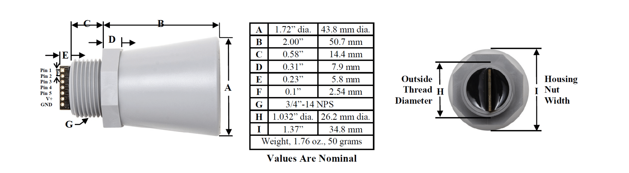
Sensor dimensions
The exact dimensions of the sensor can be found in the picture below:
MaxBotix sensor outputs
As you might have seen in the specifications table above, the MaxBotix sensors of the MaxSonar family have different outputs: analog voltage, pulse width and RS232 serial (I2C sensors are also available). In this tutorial we will look at both the analog voltage and pulse width outputs.
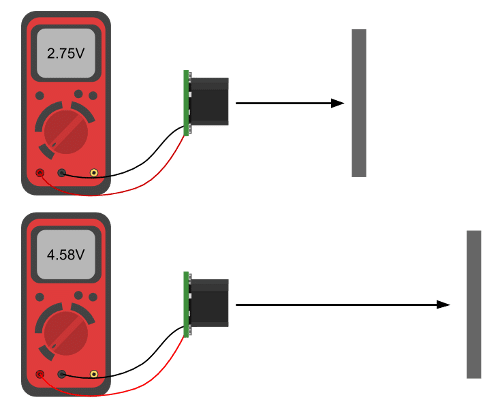
Analog voltage
This is probably the easiest way to read the measured distance from the sensor. The analog voltage output of the sensor outputs a linear voltage that gets larger as a target moves further away from the sensor.
We can read this output with a microcontroller like the Arduino and calculate the distance by multiplying the reading by a constant scaling factor (this factor depends on the exact sensor type, see datasheet).
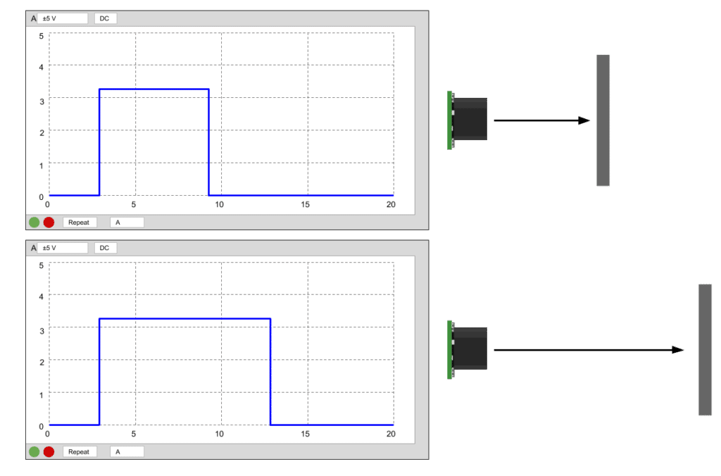
Pulse width
Another option is to use the pulse width output. This pin outputs a pulse width representation of the distance. You can use the pulseIn() function in the Arduino code to read the length of this output pulse in microseconds (µs). To get the distance, you need to multiply this reading with a constant scaling factor. For the MB7389, the scaling factor is 1 µs/mm. So you can simply multiply the TOF reading by 1 to get the distance in millimeters.
For other types of sensors, you can find the scaling factors in the datasheets.
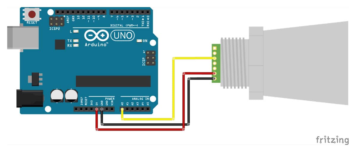
Wiring – Connecting MaxBotix MB7389 to Arduino UNO
As mentioned in the introduction, MaxBotix sensors can be operated in different modes. The wiring diagrams below show you how you can connect the MB7389 sensor to the Arduino for analog voltage or pulse width operation.
You can solder the wires directly to the sensor, or install some header pins or a connector.
The connections are also given in the following table:
MB7389 Connections – Analog voltage
| MaxBotix MB7389 Sensor | Arduino |
|---|---|
| GND | GND |
| V+ | 5 V |
| Pin 3 | A0 |
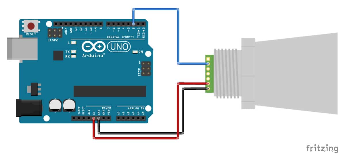
MB7389 Connections – Pulse width
| MaxBotix MB7389 Sensor | Arduino |
|---|---|
| GND | GND |
| V+ | 5 V |
| Pin 2 | Pin 2 |
Which output you should use depends on the application. One important difference is that the analog voltage output shows the distance with a resolution of 5 mm, whereas the pulse width output gives a 1 mm resolution.
MaxBotix MB7389 Arduino example code – Analog voltage
With the following example code, you can read the distance from the analog output of the sensor and display it on the serial monitor. As you can see, the code is very simple but you can find some explanation on how it works below.
You can upload the example code with the Arduino IDE.
/* Arduino example code for MaxBotix MB7389 HRXL-MaxSonar-WR
   weather resistant ultrasonic distance sensor:
   analog voltage output.
   More info: www.www.makerguides.com */

#define sensorPin A0

int distance = 0;

void setup() {
  Serial.begin(9600);
}

void read_sensor() {
  distance = analogRead(sensorPin) * 5;
}

void print_data() {
  Serial.print("distance = ");
  Serial.print(distance);
  Serial.println(" mm");
}

void loop() {
  read_sensor();
  print_data();
  delay(1000);
}
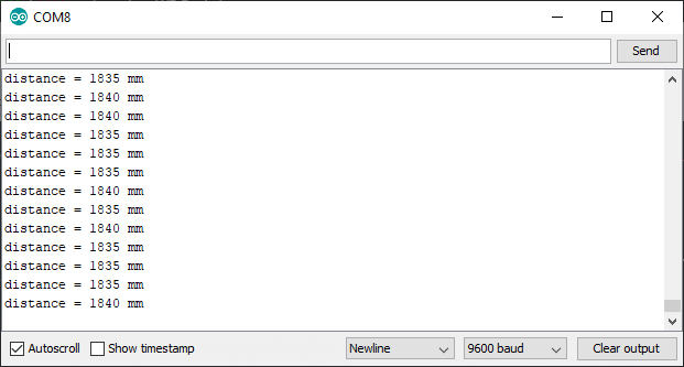
You should see the following output on the Serial Monitor (Ctrl + Shift + M).
How the code works
The first step is to define the connection pin. The statement #define is used to give a name to a constant value. When the program is compiled, the compiler will replace any references to this constant with the defined value. So everywhere you mention sensorPin, the compiler will replace it with A0 when the program is compiled.
#define sensorPin A0
Next, we need to create a variable to store the measured distance.
int distance = 0;
In the setup, we initialize serial communication at a baud rate of 9600. Later we will display the measured distance in the serial monitor, which can be accessed with Ctrl + Shift + M or Tools > Serial Monitor. Make sure that the baud rate is also set to 9600 in the serial monitor.
void setup() {
  Serial.begin(9600);
}
After this, I created two functions: read_sensor and print_data.
In the read_sensor function, we simply read the analog voltage sensor output with the function analogRead(pin). The Arduino boards contain a multichannel, 10-bit analog to digital converter. This means that it will map the input voltage between 0 and the operating voltage into integer values between 0 and 1023. On an Arduino Uno, this results in 5 volts / 1024 units or, 4.9 mV per unit.
The MB7389 uses a scaling factor of (Vcc/5120) per 1-mm or 0.98 mV/mm when using a 5 V power supply. This makes converting the analogRead value to mm super easy, you can simply multiply the result by 5. Note that this means that the analog voltage output shows the distance with a 5 mm resolution.
void read_sensor() {
  distance = analogRead(sensorPin) * 5;
}
In the print_data function, we print the measured distance to the serial monitor.
void print_data() {
  Serial.print("distance = ");
  Serial.print(distance);
  Serial.println(" mm");
}
In the loop, we first call the read_sensor function to get the distance and then call the print_data function to send it to the serial monitor. I added a delay of 1000 milliseconds, but you could reduce this to 150 if you want. The reading frequency of the MB7389 is 6.66 Hz so you can take 6.66 readings per second.
void loop() {
  read_sensor();
  print_data();
  delay(1000);
}
MaxBotix MB7389 Arduino example code – Pulse width
In this example, we will be using the other output of the sensor: the pulse width output.
/* Arduino example code for MaxBotix MB7389 HRXL-MaxSonar-WR weather resistant ultrasonic distance sensor: pulse width output. More info: www.www.makerguides.com */

#define sensorPin 2

long distance = 0;
long duration = 0;

void setup() {
  pinMode(sensorPin, INPUT);
  Serial.begin(9600);
}

void read_sensor() {
  duration = pulseIn(sensorPin, HIGH);
  distance = duration;
}

void print_data() {
  Serial.print("distance = ");
  Serial.print(distance);
  Serial.println(" mm");
}

void loop() {
  read_sensor();
  print_data();
  delay(1000);
}
Code explanation
After defining the connection pin, I created two variables: duration and distance. Duration stores the length of the pulse sent by the sensor. The distance variable is used to store the calculated distance.
long distance = 0;
long duration = 0;
In the setup, besides initializing serial communication, we also need to set the sensorPin as an INPUT. For this we use the function pinMode(pin, mode).
void setup() {
  pinMode(sensorPin, INPUT);
  Serial.begin(9600);
}
The read_sensor function is different from the previous example. Now we will not measure the analog voltage output, but the length of the pulse sent by the sensor. For this we use the function pulseIn(pin, value). This function waits for the pin to go from LOW to HIGH, starts timing, then waits for the pin to go LOW and stops timing. It returns the length of the pulse in microseconds.
After this, we can calculate the distance in mm. For the MB7389 sensor, the scaling factor is simply 1 μs/mm, so distance = duration. For other MaxBotix sensors, you can find this scaling factor in the datasheet.
void read_sensor() {
  duration = pulseIn(sensorPin, HIGH);
  distance = duration;
}
The rest of the code is the same as the previous example.
If you are planning to implement the sensor for bin level monitoring/measurement, I recommend taking multiple readings in a row and then calculate the average or mean of those readings. In my setup, the readings fluctuated by ± 3 mm.
Trigger mode operation
All the MaxSonar sensors will operate in free-running mode by default. What this means is that the sensor will continue to range until the power is removed from the sensor. It sends out twenty 42kHz waves every 150 ms (6.66 Hz reading rate for MB7389, see datasheet for other sensors).
This is generally the easiest way to operate the sensor, as you do not have to trigger it yourself and can just take an analog voltage or pulse width reading to get the distance.
For some applications, like when running the sensor from a battery, it can be better to operate the sensor with a trigger. What this means is that you can tell the sensor to start a ranging cycle, but only when it is instructed to. This way, you can control the highest current draw from the sensor which is when it transmits a sonar pulse.
To operate the sensor with a trigger, we will use an extra connection between pin 4 of the sensor and the Arduino. When you do not connect anything to this pin, like in the previous examples, the sensor will range at the refresh rate of the sensor mentioned in the sensor’s datasheet.
To trigger the sensor when needed, you need to connect pin 4 to a logic low. When you want to take a reading, you have to pull pin 4 high for a minimum of 20 μs. The sensor will then start a ranging cycle.
In this example, we will be using a momentary push button to trigger the sensor. You can buy these nice round push buttons on Amazon, that you can just plug into a breadboard. Connect one of the legs to ground and the diagonally opposite leg to Arduino pin 4.
The connections are also given in the table below.
MB7389 Connections – Trigger mode
| Pin | Arduino |
|---|---|
| GND | GND |
| V+ | 5 V |
| Pin 2 | Pin 2 |
| Pin 4 | Pin 3 |
| Button pin 1 | Pin 4 |
| Button pin 2 | GND |
MaxBotix MB7389 Arduino example code – Trigger with push button
You can use this example sketch to control the sensor with a trigger. In this case, the sensor will take a reading when you press the button and display the distance measurement on the Serial Monitor. You can also just call the read_sensor function when you want to take a reading.
/* Arduino example code for MaxBotix MB7389 HRXL-MaxSonar-WR
   weather resistant ultrasonic distance sensor with push button.
   More info: www.www.makerguides.com */

#define readPin 2
#define triggerPin 3
#define buttonPin 4

long distance = 0;
long duration = 0;

int buttonState = HIGH;
int previous = HIGH;
long time = 0;
long debounce = 200;

void setup() {
  pinMode(readPin, INPUT);
  pinMode(buttonPin, INPUT_PULLUP);
  pinMode(triggerPin, OUTPUT);
  digitalWrite(triggerPin, LOW);
  Serial.begin(9600);
  delay(3000);
  Serial.println("Sensor is ready, waiting for button press!");
}

void read_sensor() {
  digitalWrite(triggerPin, HIGH);
  delayMicroseconds(20);
  digitalWrite(triggerPin, LOW);
  duration = pulseIn(readPin, HIGH);
  distance = duration;
  delay(150);
}

void print_data() {
  Serial.print("distance = ");
  Serial.print(distance);
  Serial.println(" mm");
}

void loop() {
  buttonState = digitalRead(buttonPin);

  if (buttonState == LOW && previous == HIGH && millis() - time > debounce) {
    read_sensor();
    print_data();
    time = millis();
  }

  previous = buttonState;
}
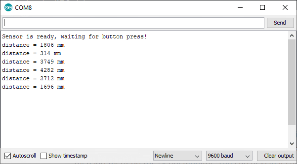
You should see the following output in the Serial Monitor (Ctrl + Shift + M).
How the code works
The first step is to define the connections. We will be using the pulse width output of the sensor to read the distance.
#define readPin 2
#define triggerPin 3
#define buttonPin 4
Besides the duration and distance variables that we used in the previous example, we also need some new variables to store the state of the button. The time and debounce variables are used to debounce the input.
You can increase the debounce time if you are getting false triggers.
long distance = 0;
long duration = 0;

int buttonState = HIGH;
int previous = HIGH;
long time = 0;
long debounce = 200;
In the setup, we set the triggerPin as output and the read and buttonPin as input. Note that I used INPUT_PULLUP in the pinMode function. There are 20K pullup resistors built into the Atmega chip that can be accessed from software. This setting pulls the buttonPin HIGH when it is not pressed and it will turn LOW when you press the button.
Next, we set the triggerPin LOW, so the sensor will not start ranging.
To print the sensor data, we begin serial communication at a baud rate of 9600.
void setup() {
  pinMode(readPin, INPUT);
  pinMode(buttonPin, INPUT_PULLUP);
  pinMode(triggerPin, OUTPUT);
  digitalWrite(triggerPin, LOW);
  Serial.begin(9600);
  delay(3000);
  Serial.println("Sensor is ready, waiting for button press!");
}
After this, I defined two functions, the read_sensor and print_data function.
In the read_sensor function, you can see that we set the triggerPin high for 20 microseconds. This will tell the sensor to send out a sonar pulse. Next, we read the length of the output pulse and convert it into the distance (this is the same as the previous example). I added a delay of 100 ms, as this is the minimum time between readings.
The print_data function is the same as in the previous examples.
void read_sensor() {
  digitalWrite(triggerPin, HIGH);
  delayMicroseconds(20);
  digitalWrite(triggerPin, LOW);
  duration = pulseIn(readPin, HIGH);
  distance = duration;
  delay(150);
}
In the loop, we first read the state of the button (pressed / not pressed) and store it as buttonState. The next line checks if you have pressed the button (i.e. the input went from HIGH to LOW) and if you have waited long enough since the last press to ignore any noise.
If this is true, it calls the read_sensor and print_data function and resets the timer.
void loop() {
  buttonState = digitalRead(buttonPin);

  if (buttonState == LOW && previous == HIGH && millis() - time > debounce) {
    read_sensor();
    print_data();
    time = millis();
  }

  previous = buttonState;
}
Finally, the previous variable is set to the current buttonState.
CAD
MaxBotix provides free CAD files for all their sensors on their website. This makes designing custom parts or brackets to use with the sensor super easy. You can download a zip file with a 3D model of the sensor below (7 different file formats). More models of different sensors can be found on their website.
Conclusion
In this article, I have shown you how you can use the MaxBotix MB7389 HRXL-MaxSonar-WR weather-resistant ultrasonic distance sensor with Arduino. I hope you found it useful and informative. If you did, please share it with a friend who also likes electronics and making things!
I would love to know what projects you plan on building (or have already built) with this sensor. If you have any questions, suggestions or if you think that things are missing in this tutorial, please leave a comment down below.
Note that comments are held for moderation to prevent spam.
Benne is professional Systems Engineer with a deep expertise in Arduino and a passion for DIY projects.
Zeeshan Khan
Monday 18th of December 2023
Hey . These ultrasonic sensor have auto sensitivity adjustment noise,rejection how do they that is it using hardware on the board of the sensors or using some algorithms ?
Stefan Maetschke
Monday 18th of December 2023
Yes, there is additionally electronics and not just the plain ultrasonic transducer.
Bill
Sunday 3rd of May 2020
I find your article using the Arduino Uno interesting and informative. I have an Arduino and two Maxbotix sensors. I am attempting to put together a device that will help get a car in the garage without taking the side mirrors off! The principal that I want to do is to use two sensor, subtract the two and if within a range, output a signal to one of three displays, left, right or OK. I plan on using the serial output for accuracy so was looking for timing signals required for the Arduino. I am using the differential method because an autos front surface is irregular and probably not too repeatable accurate. It's an experiment but right now I need to know how to program Arduino. If you have any tips I would appreciate it. Bill