This article will guide you through the basics of using an RGB LED in Arduino, so you can create your own colors with the help of potentiometers.
I’ll show you step-by-step wiring diagrams and explain the code so you can fully understand how to use this component.
After this tutorial, you should have a circuit that shines a light in your preferred color using RGB values, which are controlled by potentiometers and shown in the Serial Monitor.
Supplies
Makerguides.com is a participant in the Amazon Services LLC Associates Program, an affiliate advertising program designed to provide a means for sites to earn advertising fees by advertising and linking to products on Amazon.com. As an Amazon Associate we earn from qualifying purchases.
Hardware
- x1 Arduino Uno Rev3 (Amazon)
- x1 RGB LED, common cathode (Amazon)
- x3 220 Ohm Resistors (Amazon)
- x3 10k Ohm Potentiometers (Amazon)
- x1 Breadboard (Amazon)
- x~17 Jumper Wires (Amazon)
- x1 USB B Cable (Amazon)
Software
- Arduino IDE
You can also find RGB LEDs in KY-016 modules, which have the LED and necessary resistors in a single PCB.
These modules don’t allow for any flexibility while building the circuit, but they are more plug-and-play than their alternatives.
I wouldn’t recommend these, I prefer the flexibility of using resistors, and some reviews show poor colour reproduction when using RGB values.
Instructions
Step 1 – Connecting the RGB LED
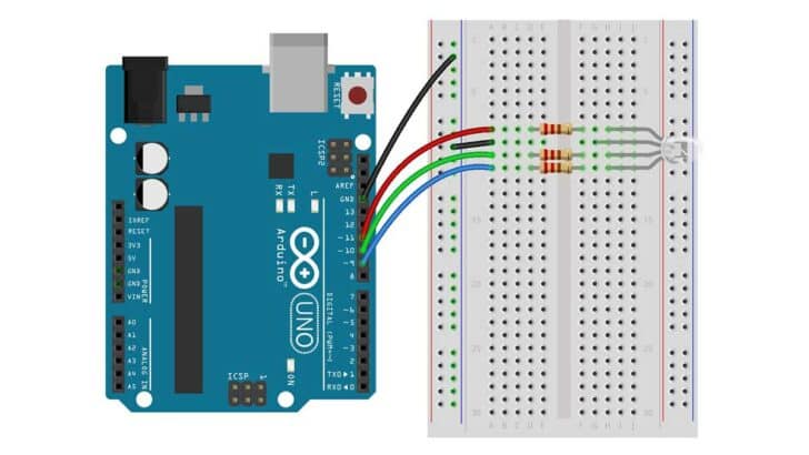
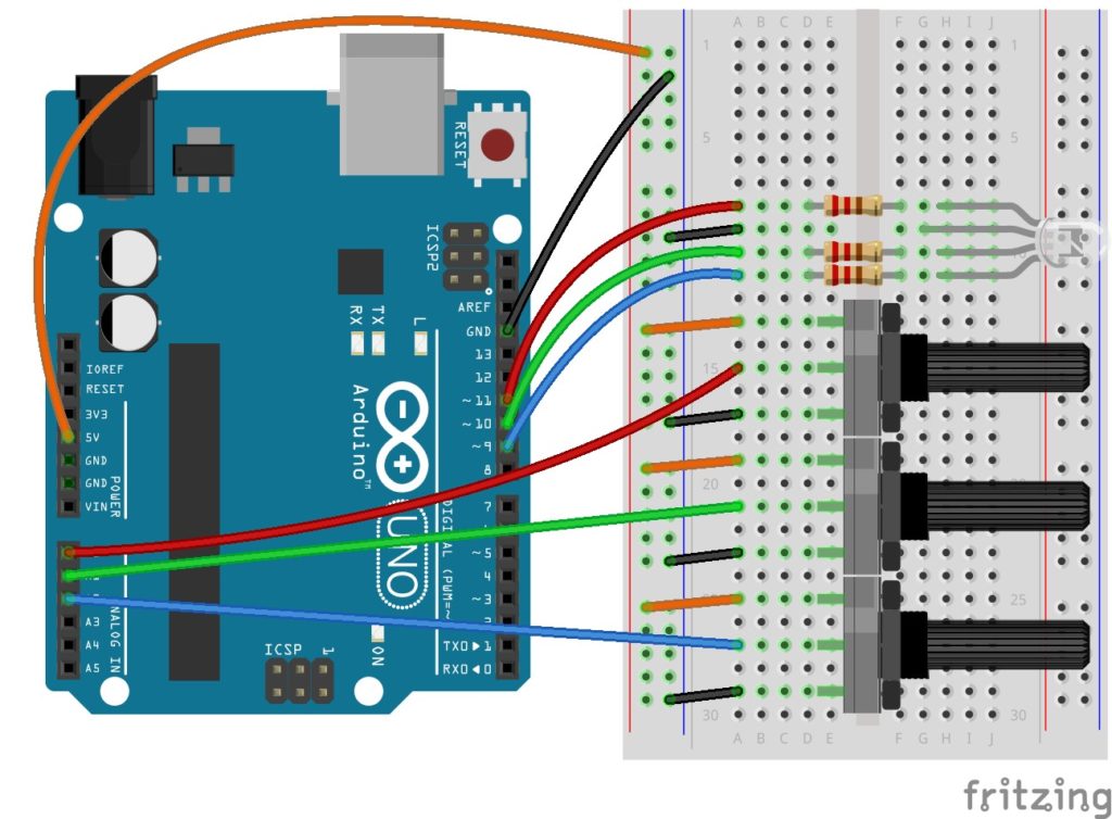
This wiring diagram shows you how to connect an RGB LED to the Arduino board.
Note that this is a common cathode LED, in which the longer pin is connected to ground, further ahead I’ll explain what common cathode means.
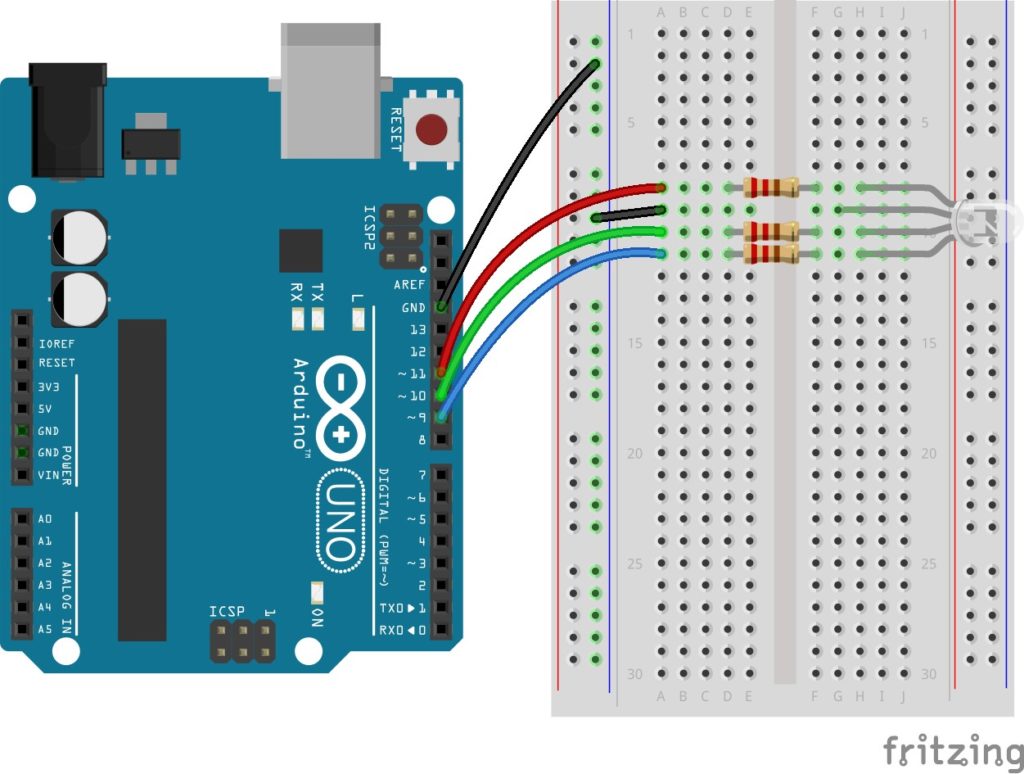
The connections are also given in the table below.
| Component | Arduino Pin |
| LED – Red | 11 |
| LED – Cathode | GND |
| LED – Green | 10 |
| LED – Blue | 9 |
Make sure to include a 220Ω resistor between the red, green, and blue pins of the LED and the outputs to avoid damage to the LED and the Arduino.
RGB LED Basics
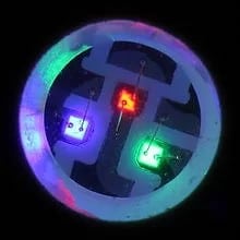
An RGB LED can be seen as three LEDs —one red, one green, and one blue— in a single package, this single LED shines in the combination of the red, green, and blue intensities.
RGB LEDs look like normal LEDs with four pins, the longest one being the common pin.
Common Cathode and Common Anode RGB LEDs
I previously mentioned common cathode and common anode LEDs. RGB LEDs come in two types: common cathode and common anode.
In common cathode LEDs the longer pin gets connected to GND and its components are lit by a 5V signal, in common anode LEDs it’s the opposite: longer pin goes to 5V, a 0V signal turns components on.
In this example, we’ll be using common cathode LEDs, if you happen to have a common anode RGB LED the wiring and outputs will have to be inverted.
The only way to tell if your RGB is common cathode or common anode is to test the LED, I would recommend testing with a multimeter using the diode function.
To test this take the negative probe to the common pin and the positive probe to any other pin, if the LED lights up it is common cathode.
If not, take the positive probe to the common pin and the negative probe to any other pin, the LED should light up meaning it is common anode.
If you don’t have a multimeter you can do this with the 5V and GND pins on the Arduino, just make sure that you have a 220Ω resistance in your circuit.
Controlling the LED Brightness with PWM
How bright an LED shines is controlled by how much current flows through it, but we cannot directly control the current as the Arduino Uno lacks fully analog outputs, to control its brightness we’ll be using Pulse Width Modulation (PWM).
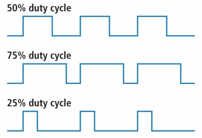
PWM turns the output on and off periodically, and how long the output remains on determines the brightness of the LED.
PWM turns the output on and off periodically, and how long the output remains on determines the brightness of the LED.
The intensity of the LED is determined by the PWM duty cycle, this is how much time the output remains on. A 50% duty cycle means the output is high 50% of the time and low the other 50% of the time.
This cycle occurs at 490 Hz, 490 times a second, and you can control this duty cycle with AnalogWrite.
PWM turns the output on and off periodically, and how long the output remains on determines the brightness of the LED.
Step 2 – Connecting the Three Potentiometers
For this step, you need to connect three potentiometers to 5V, GND, and the analog pins A0, A1, and A2.
The outermost legs will be connected to 5V and GND, the middle leg connects to the analog pins according to this figure:
In table form:
| Component | Arduino Pin |
| Rightmost pin (any) | 5V |
| Leftmost pin (any) | GND |
| Middle pin (red) | A0 |
| Middle pin (green) | A1 |
| Middle pin (blue) | A2 |
Using a Potentiometer as an Analog Input
To control the values of the RGB LED, you’ll be using the outputs of the potentiometers (middle pin) as analog inputs.
Arduino Uno has 6 analog inputs, labeled A0 to A5; these involve a 10-bit Analog to Digital Converter (ADC) with 6 channels.
This analog to digital converter will return a number from 0 to 1023 (1024 bits = 2¹⁰ = 10 bits), depending on the voltage it reads in a channel.
We will change the PWM duty cycle of the LED components according to this value.
You can consider a potentiometer in this circuit as a voltage divider: as you turn the knob the resistance of the middle pin will change, and so will the voltage.
This will “divide” the 5V input into two parts if you measure voltage between the output and 5V, and between the output and GND.
Step 3: Arduino RGB LCD Example Code
Now that the wiring is done all that’s left is to connect the Arduino to your PC and upload the sketch.
You can upload the following code through the Arduino IDE, you can copy the code by clicking on the button in the top right corner of the code field.
/*Example sketch to control an RGB LED with Arduino using potentiometers
More info: https://www.makerguides.com */

//Definition of pins: outputs
#define redPin 11
#define greenPin 10
#define bluePin 9

//Definition of pins: analog inputs
#define redPot A0
#define greenPot A1
#define bluePot A2

int redVal, greenVal, blueVal; // RGB component values

void setup() {
  //Pin definitions
  pinMode(redPin, OUTPUT);
  pinMode(greenPin, OUTPUT);
  pinMode(bluePin, OUTPUT);

  pinMode(redPot, INPUT);
  pinMode(greenPot, INPUT);
  pinMode(bluePot, INPUT);

  Serial.begin(9600);
}

void loop() {
  //Reading potentiometer values
  //When the pot is in the leftmost position, the voltage reading is 0
  redVal = analogRead(redPot)/4;
  greenVal = analogRead(greenPot)/4;
  blueVal = analogRead(bluePot)/4;

  //Sets the individual colors with the pot values
  analogWrite(redPin, redVal);
  analogWrite(greenPin, greenVal);
  analogWrite(bluePin, blueVal);

  delay(50);

  //Printing the values of Red, Green and Blue in a single line
  Serial.print("R: "); Serial.print(redVal);
  //The \t character creates a tab space between colors
  Serial.print("\tG: "); Serial.print(greenVal);
  //Final value is Serial.println to create a new line between readings
  Serial.print("\tB: "); Serial.println(blueVal);
}
How the Code Works
The first step is to define the relevant pins, this is done through the #define statement which will replace the defined keyword with our desired value when the program compiles.
With this we define the red, green and blue LED outputs as pins 11, 10 and 9 respectively.
Then we do the same procedure with the potentiometer inputs, using the analog pins A0, A1, and A2.
I also defined three global variables, one for each RGB pin. These values are defined as integers, you want to use them every time you deal with whole numbers.
An integer’s value can go between -2,147,483,648 to 2,147,483,647. If you wish to be more efficient with the Arduino’s memory you can use the data type byte, which ranges from 0 to 255.
This is not necessary in this simple example but is useful to keep in mind in more complex sketches.
//Definition of pins: outputs
#define redPin 11
#define greenPin 10
#define bluePin 9

int redVal, greenVal, blueVal; //RGB component values
In the setup() function of the sketch we define the LED pins as Outputs, and the potentiometer pins as inputs using the pinMode() function.
Then we begin the Serial buffer at 9600 baud using Serial.begin(9600), with this function you will be able to read the color values you print in a further section of the sketch.
void setup() {
  //Pin definitions
  pinMode(redPin, OUTPUT);
  pinMode(greenPin, OUTPUT);
  pinMode(bluePin, OUTPUT);

  pinMode(redPot, INPUT);
  pinMode(greenPot, INPUT);
  pinMode(bluePot, INPUT);

  Serial.begin(9600);
Now we move to the loop() function. First, we begin by reading the values of the potentiometer.
This is done using the analogRead() function, in which you specify the pin and it will return a value between 0 and 1024, as mentioned previously.
Unfortunately, to control the LEDs with the analogWrite() function we need to feed it values between 0 and 255, to do this we divide the read value by 4 and assign it to our integers.
//Reading potentiometer values
//When the pot is in the leftmost position, the voltage reading is 0V
redVal = analogRead(redPot)/4;
greenVal = analogRead(greenPot)/4;
blueVal = analogRead(bluePot)/4;
In this step I use the PWM outputs of the Arduino to light up the red, green and blue pins on the RGB led with the integer values obtained from the potentiometers, you just need to specify the pin and the number between 0 and 255.
//Sets the individual colors with the pot values
  analogWrite(redPin, redVal);
  analogWrite(greenPin, greenVal);
  analogWrite(bluePin, blueVal);
Next I introduce a small delay to the code, I do this to prevent the serial monitor from scrolling too fast while still letting the RGB LED feel responsive to inputs.
This delay last 50 milliseconds: 50 thousandths of a second or 0.05 seconds.
You can adjust this delay as you like, just note that too big of a delay will make the RGB values update slower too.
delay(50);
Finally, to check on what RGB values are being shown on the LED we will print them in the serial monitor.
For the sake of clarity, these will be printed in a single line. For this we will use the Serial.print() function.
Here I print the letter corresponding to each component in the RGB LED and its written value.I used escape character \t to create a tab spacing between each of the colors, escape characters follow a backslash and don’t show up on the printed string, as they perform special functions.
Also, the last serial function is Serial.println(), this ensures that the next serial message appears in a new line.
Serial.print("R: "); Serial.print(redVal);
Serial.print("\\tG: "); Serial.print(greenVal);
Serial.print("\\tB: "); Serial.println(blueVal);
To check the messages in the serial monitor press Ctrl+Shift+M in the Arduino IDE, or click the magnifying glass icon. Make sure the baud rate is set 9600 to correctly read the messages.
You should see something similar to the following image:
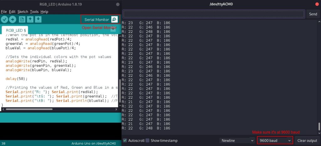
That’s it! If you followed the steps correctly you should be able to control the RGB LED and produce all sorts of colors using the potentiometers.
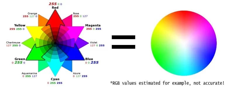
Additive Color
The property of lights of different colors combining to create a new color is called additive color.
This property makes it possible for screens to show around 16 million shades of color: setting red, green and blue lights to a value from 0 to 255 just like in our project.
You can try some of the basic combinations shown in the image below, or go to a color picker and make your own!
Results may vary though: some components in RGB LEDs are stronger than others and may require adjustment.
Conclusion
In this article, I have shown you how to use an RGB LED with Arduino: it’s wiring, the analog outputs needed, and a simple circuit that shows how to easily customize the LED color.
If you have any questions or suggestions for this tutorial, leave a comment down below.
I’d love to help you!
Benne is professional Systems Engineer with a deep expertise in Arduino and a passion for DIY projects.