The SHARP GP2Y0A710K0F is a relatively easy to use IR distance sensor with an extra long range of 100 – 500 cm. This extra long range makes it a good alternative for ultrasonic distance sensors.
In this tutorial, you will learn how the sensor works and how to use it with Arduino. I have included a wiring diagram and example code so you can start experimenting with your sensor.
If you are looking for a more affordable or waterproof distance sensor, take a look at the HC-SR04 or JSN-SR04T. In the articles below I explain how these distance/proximity sensors work and how you can use them with Arduino.
Other distance/proximity sensors:
- How to use an HC-SR04 Ultrasonic Distance Sensor with Arduino
- Waterproof JSN-SR04T Ultrasonic Distance Sensor with Arduino Tutorial
- How to use a SHARP GP2Y0A21YK0F IR Distance Sensor with Arduino
Supplies
Hardware components
| SHARP GP2Y0A710K0F IR distance sensor | × 1 | Amazon | |
| Arduino Uno Rev3 | × 1 | Amazon | |
| Breadboard | × 1 | Amazon | |
| Jumper wires | ~ 10 | Amazon | |
| Capacitor (10 µF or more) | × 1 | Amazon | |
| USB cable type A/B | × 1 | Amazon |
Software
Makerguides.com is a participant in the Amazon Services LLC Associates Program, an affiliate advertising program designed to provide a means for sites to earn advertising fees by advertising and linking to products on Amazon.com. As an Amazon Associate we earn from qualifying purchases.
How does an IR distance sensor work?
An IR distance sensor uses a beam of infrared light to reflect off an object to measure its distance. The distance is calculated using triangulation of the beam of light. The sensor consists of an IR LED and a light detector or PSD (Position Sensing Device).
When the beam of light gets reflected by an object, the reflected beam will reach the light detector and an ‘optical spot’ will form on the PSD.
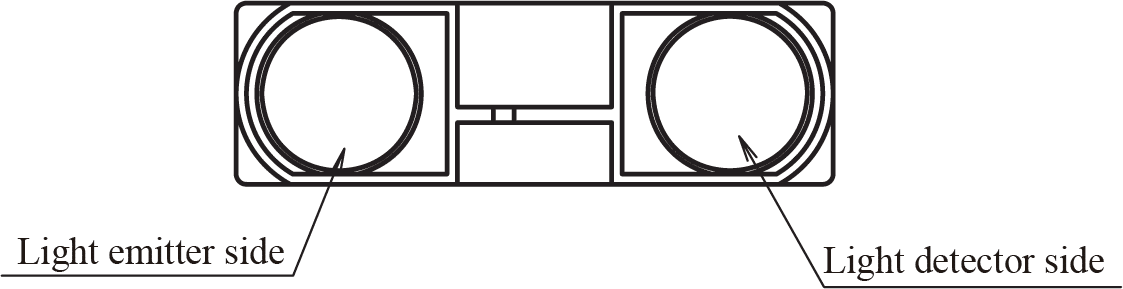
When the position of the object changes, the angle of the reflected beam and the position of the spot on the PSD changes as well. See point A and point B in the image below.

The sensor has a built-in signal processing circuit. This circuit processes the position of the optical spot on the PSD to determine the position (distance) of the reflective object. It outputs an analog signal which depends on the position of the object in front of the sensor.
How to read an IR distance sensor?
IR distance sensors output an analog signal, which changes depending on the distance between the sensor and an object. From the datasheet, you can see that the output voltage of the SHARP GP2Y0A710K0F ranges from 2.5 V when an object is 100 cm away to 1.4 V when an object is 500 cm away. The graph also shows why the usable detection range starts at 100 cm.
Notice that the output voltage of an object that is 30 cm away is the same as the output voltage for an object that is 160 cm away. The usable detection range therefore start after the peak at roughly 100 cm or 2.5 V.
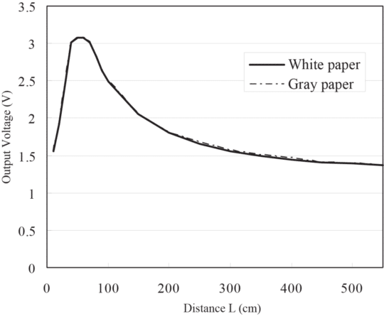
The graph also shows the drawback of these sensors, the response is non-linear. In other words, a big change in the output voltage does not always correspond to a big change in range. In order to determine the distance between the sensor and an object, you need to find a function that converts the output voltage into a range value.
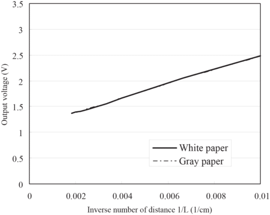
If you plot the output voltage against the inverse distance, you get a mostly linear relationship. For distances > 100 cm you get the following curve.
Distance Calculation
Based on the data from the SHARP datasheet, you can calculate the linear function:
y = 137500x + 1125
With y equal to the output voltage in mV and x equal to 1/distance in cm.
This results in the following formula for the distance between the sensor and an object:
Distance (cm) = 1/((Output_voltage_mV – 1125)/137500)
This is the function that is used in the SharpIR library, which we will be using later. Note that this function is based on data from the SHARP datasheet only. The output characteristics of the sensor will vary slightly from sensor to sensor so you might get inaccurate readings.
GP2Y0A710K0F Specifications
| Operating voltage | 4.5 to 5.5 V |
| Operating current | 30 mA |
| Measuring range | 100 to 550 cm |
| Output type | Analog |
| Dimensions | 58 x 17.6 x 22.5 mm |
| Mounting hole | 4.2 mm |
| Cost | Check price |
For more information you can check out the datasheet here.
Wiring – Connecting GP2Y0A710K0F IR sensor to Arduino
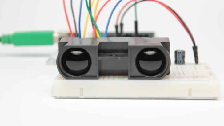
The wiring diagram below shows you how to connect the GP2Y0A710K0F IR distance sensor to an Arduino. Please note: the wire colors are not intuitive!
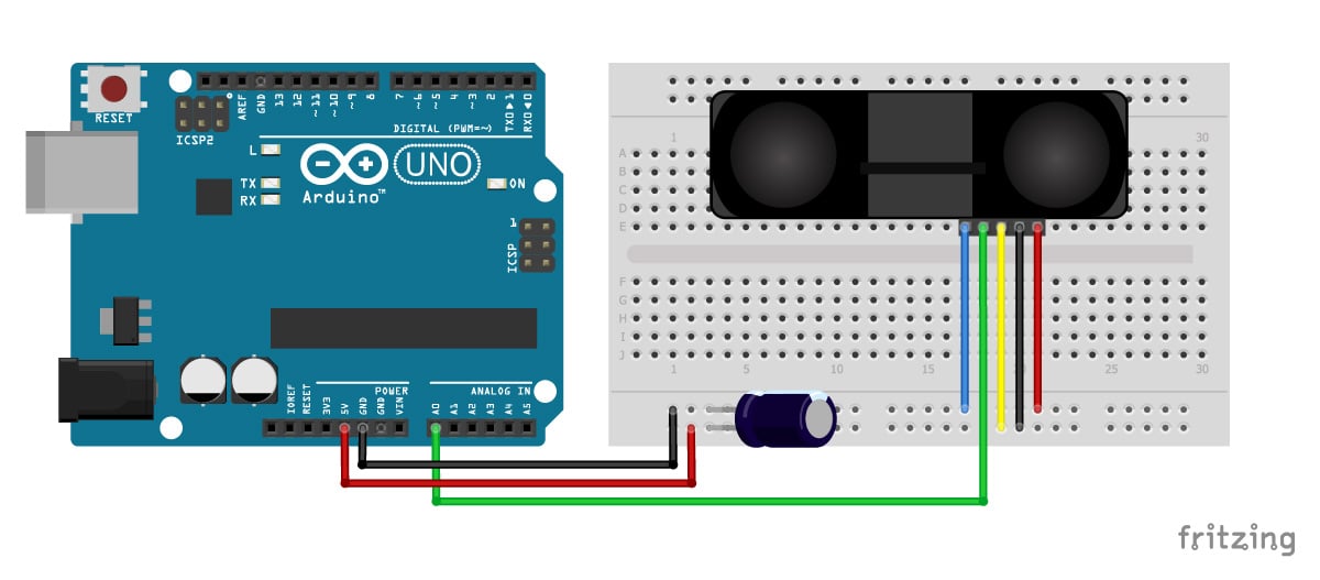
These types of distance sensors tend to be a bit noisy, so it is recommended to add a capacitor between Vcc and GND. The datasheet suggests a capacitor of 10 µF or more. Connect the positive lead of the capacitor to the Vcc wire connection and the negative lead to the GND wire connection (see picture). Capacitors are often marked with a stripe which indicates the negative lead. The positive lead is often longer than the negative lead.
GP2Y0A710K0F Connections
| GP2Y0A710K0F | Arduino |
|---|---|
| 1 (Red) | GND |
| 2 (Black) | 5V |
| 3 (Yellow) | 5V |
| 4 (Green) | A0 |
| 5 (Blue) | GND |
If your sensor comes with different colored wires, be sure to check the pinout below. The Vo pin is connected to the analog in of the Arduino (A0).
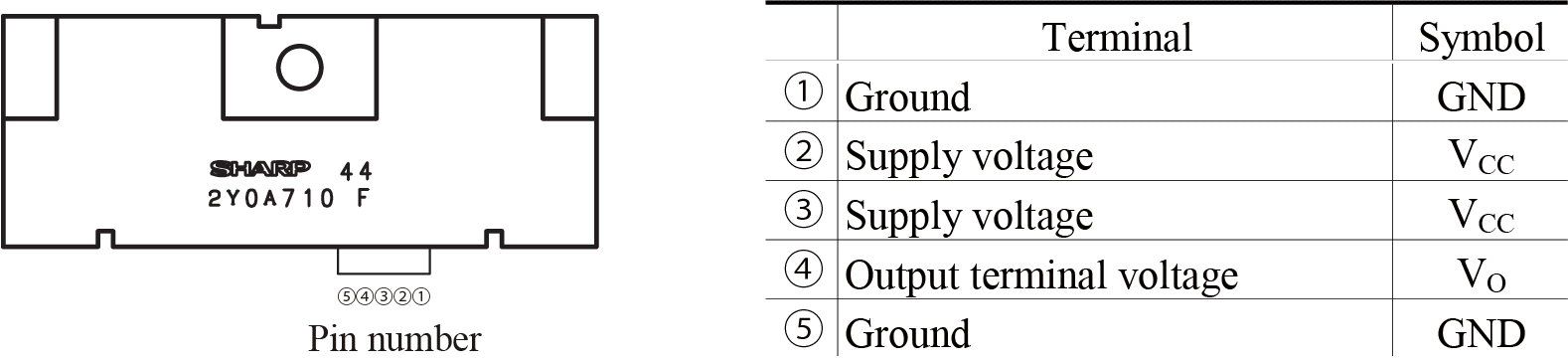
The connector of the sensor is not marked, the order of the pins corresponds to the sensor with the logo facing up.
Now that you have wired up the sensor it is time to look at some example code.
Installing the SharpIR Arduino library
The SharpIR library written by Guillaume Rico and Thibaut Mauon makes working with SHARP IR sensors a lot easier. It includes the formulas that are needed to convert the measured output voltage to a distance in centimeters. Currently, the library supports the following sensors: GP2Y0A02YK0F, GP2Y0A21YK0F, GP2Y0A710K0F, and GP2YA41SK0F. The latest version of the library can be downloaded here on GitHub or click the button below.
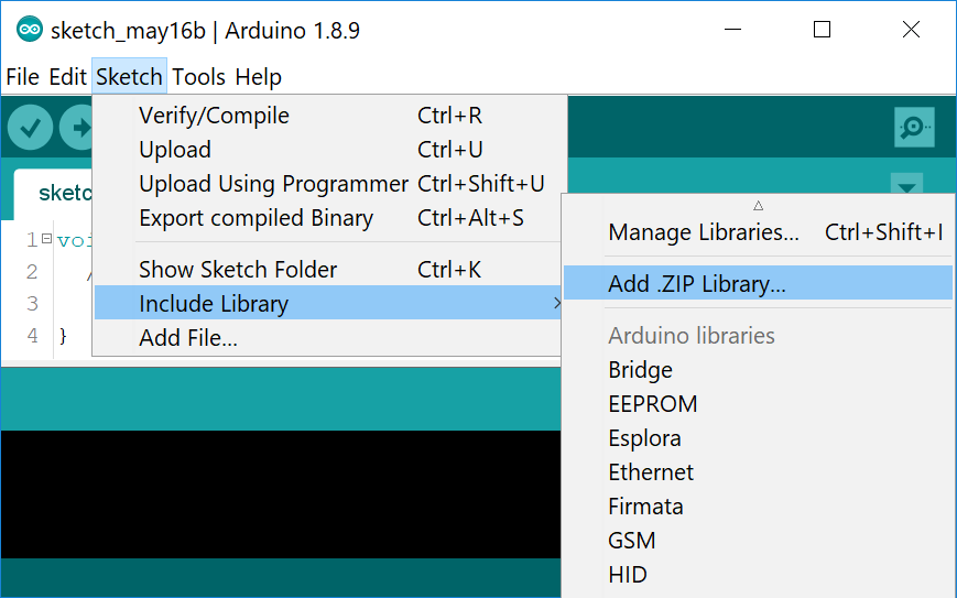
You can install the library by going to Sketch > Include Library > Add .ZIP Library in the Arduino IDE.
The author of the library noticed that the readings from the sensor can fluctuate quite a bit. The library solves this problem by taking multiple readings in a row, discarding outliers, and taking the mean to get a more stable distance reading. Currently, the library takes the mean of 25 readings, which takes roughly 53 ms.
Example code for SHARP GP2Y0A710K0F IR distance sensor with Arduino
The example code below can be used with the GP2Y0A710K0F sensor and displays the measured distance in centimeters in the serial monitor.
You can copy the code by clicking the button in the top right corner of the code field.
/*SHARP GP2Y0A710K0F IR distance sensor with
  Arduino and SharpIR library example code.
  More info: https://www.makerguides.com */

// Include the library:
#include "SharpIR.h"

// Define model and input pin:
#define IRPin A0
#define model 100500

// Create variable to store the distance:
int distance_cm;

/* Model :
  GP2Y0A02YK0F --> 20150
  GP2Y0A21YK0F --> 1080
  GP2Y0A710K0F --> 100500
  GP2YA41SK0F --> 430
*/

// Create a new instance of the SharpIR class:
SharpIR mySensor = SharpIR(IRPin, model);

void setup() {
  // Begin serial communication at a baud rate of 9600:
  Serial.begin(9600);
}

void loop() {
  // Get a distance measurement and store it as distance_cm:
  distance_cm = mySensor.distance();

  // Print the measured distance to the serial monitor:
  Serial.print("Mean distance: ");
  Serial.print(distance_cm);
  Serial.println(" cm");

  delay(1000);
}
Note that we have called the sensor ‘mySensor’ in this example. If you want to use multiple IR distance sensors, you can create another sensor object with a different name: SharpIR mySensor2 = SharpIR(IRPin2, model); Note that in that case you also use a different input pin for the second sensor.
When the output voltage is under 1.4 V or higher than 3.3 V, you will see “Mean distance: 0 cm” in the serial monitor.
Conclusion
In this article, I have shown you how the SHARP GP2Y0A710K0F IR distance sensor works and how you can use it with Arduino. I hope you found it useful and informative. If you did, please share it with a friend that also likes electronics!
I would love to know what projects you plan on building (or have already built) with this IR distance sensor. If you have any questions, suggestions, or if you think that things are missing in this tutorial, please leave a comment down below.
Note that comments are held for moderation to prevent spam.
Benne is professional Systems Engineer with a deep expertise in Arduino and a passion for DIY projects.
Donald
Saturday 11th of February 2023
// Get a distance measurement and store it as distance_cm: distance_cm = mySensor.getDistance();
Nandana.P
Wednesday 4th of May 2022
Hi My project was to make IR proximity sensor...how can I add distance measuring to that project using arduino ? And how can we write the code accordingly ?
Praveen
Tuesday 22nd of March 2022
Hi I am thinking of designing distance measurement for about 4-5 meters on car bumper. kindly suggest Hardwre and Software requirements using arduino.
Oliver
Wednesday 29th of May 2019
Hello I would like to use this sensor. But for my project it would help if I could use mm output instead of cm - is this possible?
Benne de Bakker
Wednesday 29th of May 2019
Hi,
There is no default mm function in this library. You would need to change the SharpIR.cpp file of the library. This is where the raw data is transformed to cm. You should be able to find the file in your libraries folder or via the GitHub link. But I have to say that I don't think the sensor is accurate enough to measure in mm.