In this tutorial, you will learn how to control a stepper motor with the TB6560 microstepping driver and Arduino. This driver is easy to use and can control large stepper motors like a 3 A NEMA 23.
I have included a wiring diagram and 2 example codes. In the first example, I will show you how you can use this stepper motor driver without an Arduino library. In the second example, we will take a look at the AccelStepper library. This library is fairly easy to use and allows you to add acceleration and deceleration to the movement of the stepper motor.
After each example, I break down and explain how the code works, so you should have no problems modifying it to suit your needs.
If you would like to learn more about other stepper motor drivers, then the articles below might be useful:
- TB6600 Stepper Motor Driver with Arduino Tutorial
- How to control a stepper motor with A4988 driver and Arduino
- 28BYJ-48 Stepper Motor with ULN2003 Driver and Arduino Tutorial
- How to control a Stepper Motor with Arduino Motor Shield Rev3
Supplies
Hardware components
| TB6560 stepper motor driver | × 1 | Amazon | |
| NEMA 23 stepper motor | × 1 | Amazon | |
| Arduino Uno Rev3 | × 1 | Amazon | |
| Power supply (24 V) | × 1 | Amazon | |
| Jumper wires | × 4 | Amazon | |
| USB cable type A/B | × 1 | Amazon |
Tools
| Wire stripper | Amazon | ||
| Small screwdriver | Amazon | ||
| Self-adjusting crimping pliers (recommended)* | Amazon | ||
| Wire ferrules assortment (recommended)* | Amazon |
*Hackaday wrote a great article on the benefits of using wire ferrules (also known as end sleeves).
Software
Makerguides.com is a participant in the Amazon Services LLC Associates Program, an affiliate advertising program designed to provide a means for sites to earn advertising fees by advertising and linking to products on Amazon.com. As an Amazon Associate we earn from qualifying purchases.
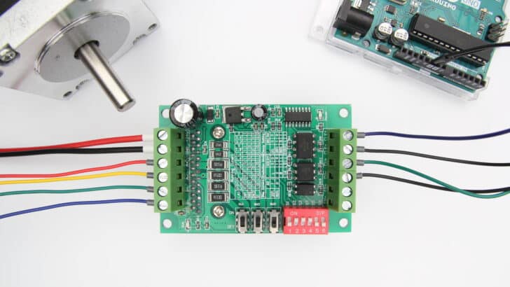
About the driver
The TB6560 microstepping driver is built around the Toshiba TB6560AHQ chip and it can be used to drive two-phase bipolar stepper motors.
With a maximum current of 3 A continuous, the TB6560 driver can be used to control quite large stepper motors like a NEMA 23. Make sure that you do not connect stepper motors with a current rating of more than 3 A to the driver.
The chip has several safety functions built-in like over-current, under-voltage shutdown, and overheating protection. However, it does not have reverse-voltage protection, so make sure that you connect the power supply correctly. You can find more specifications in the table below.
TB6560 Specifications
| Operating voltage | 10 – 35 VDC, 24 VDC recommended |
| Max output current | 3 A per phase, 3.5 A peak |
| Microstep resolution | full, 1/2, 1/8 and 1/16 |
| Protection | Low-voltage shutdown, overheating and over-current protection |
| Dimensions | 75 x 50 x 35 mm |
| Hole spacing | 69 x 43 mm, ⌀ 3.5 mm |
| Cost | Check price |
For more information, you can check out the datasheet/manual below:
Note that the TB6560 is an analog driver. In recent years, digital drivers like the DM556 or DM542 have become much more affordable. Digital drivers usually give much better performance and quieter operation. They can be wired and controlled in the same way as the TB6560, so you can easily upgrade your system later.
I have used the DM556 drivers for my DIY CNC router and they have been working great for several years.
TB6560 vs TB6600
When shopping for a TB6560 stepper motor driver, you will probably come across the slighly more expensive TB6600 driver as well. This driver can be controlled with the same code/wiring, but there are some key differences.
| TB6560 | TB6600 | |
|---|---|---|
| Operating voltage | 10 – 35 VDC, 24 VDC recommended | 9 – 42 VDC, 36 VDC recommended |
| Max output current | 3 A per phase, 3.5 A peak | 3.5 A per phase, 4 A peak |
| # Current settings | 14 | 8 |
| Microstep resolution | full, 1/2, 1/8 and 1/16 | full, 1/2, 1/4, 1/8, 1/16 and 1/32 |
| Clock frequency | 15 kHz | 200 kHz |
| Cost | Check price | Check price |
So the main differences are the higher maximum voltage, higher maximum current, and up to 1/32 microstepping. If you want to control larger stepper motors or need a higher resolution, I recommend going with the TB6600.
Wiring – Connecting TB6560 to stepper motor and Arduino
The wiring diagram below shows you how you can connect the TB6560 stepper motor driver to the Arduino and a stepper motor.
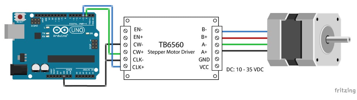
In this tutorial, we will be connecting the driver in a common cathode configuration. This means that we connect all the negative sides of the control signal connections together to ground.
The connections are also given in the table below:
TB6560 Connections
| TB6560 | Connection |
|---|---|
| VCC | 10 – 35 VDC |
| GND | Power supply ground |
| EN- | Not connected |
| EN+ | Not connected |
| CW- | Arduino GND |
| CW+ | Pin 2 Arduino |
| CLK- | Arduino GND |
| CLK+ | Pin 3 Arduino |
| A-, A+ | Coil 1 stepper motor |
| B-, B+ | Coil 2 stepper motor |
Note that we have left the enable pins (EN- and EN+) disconnected. This means that the enable pin is always LOW and the driver is always enabled.
How to determine the correct stepper motor wiring?
If you can’t find the datasheet of your stepper motor, it can be difficult to figure out which color wire goes where. I use the following trick to determine how to connect 4 wire bipolar stepper motors:
The only thing you need to identify is the two pairs of wires which are connected to the two coils of the motor. The wires from one coil get connected to A- and A+ and the other to B- and B+, the polarity doesn’t matter.
To find the two wires from one coil, do the following with the motor disconnected:
- Try to spin the shaft of the stepper motor by hand and notice how hard it is to turn.
- Now pick a random pair of wires from the motor and touch the bare ends together.
- Next, while holding the ends together, try to spin the shaft of the stepper motor again.
If you feel a lot of resistance, you have found a pair of wires that is connected to the same coil. The other pair of wires are connected to the second coil.
If you can still spin the shaft freely, try another pair of wires. Now connect the two coils to the pins shown in the wiring diagram above.
(If it is still unclear, please leave a comment below, more info can also be found on the RepRap.org wiki)
TB6560 microstep settings
Stepper motors typically have a step size of 1.8° or 200 steps per revolution, this refers to full steps. A microstepping driver such as the TB6560 allows higher resolutions by allowing intermediate step locations. This is achieved by energizing the coils with intermediate current levels.
For instance, driving a motor in 1/2 step mode will give the 200-steps-per-revolution motor 400 microsteps per revolution.
You can change the TB6560 microstep setting or excitation mode by switching the dip switches on the driver on or off. See the table below for details. Make sure that the driver is not connected to power when you adjust the dip switches!
Microstep table
| S3 | S4 | Microstep resolution |
|---|---|---|
| OFF | OFF | Full step |
| ON | OFF | 1/2 step |
| ON | ON | 1/8 step |
| OFF | ON | 1/16 step |
Generally speaking, a smaller microstep setting will result in a smoother and quieter operation. It will however limit the top speed that you can achieve when controlling the stepper motor driver with an Arduino.
TB6560 current settings
You can adjust the current that goes to the motor when it is running by setting the dip switches SW1, SW2, SW3, and S1 on or off. I recommend starting with a current level of 1 A. If your motor is missing steps or stalling, you can always increase the current level later.
Current table
| (A) | SW1 | SW2 | SW3 | S1 |
|---|---|---|---|---|
| 0.3 | OFF | OFF | ON | ON |
| 0.5 | OFF | OFF | ON | OFF |
| 0.8 | OFF | ON | OFF | ON |
| 1 | OFF | ON | OFF | OFF |
| 1.1 | OFF | ON | ON | ON |
| 1.2 | ON | OFF | OFF | ON |
| 1.4 | OFF | ON | ON | OFF |
| 1.5 | ON | OFF | ON | ON |
| 1.6 | ON | OFF | OFF | OFF |
| 1.9 | ON | ON | OFF | ON |
| 2 | ON | OFF | ON | OFF |
| 2.2 | ON | ON | ON | ON |
| 2.6 | ON | ON | OFF | OFF |
| 39 | ON | ON | ON | OFF |
The stop current is the current used to hold the motor shaft at a stopped position. You will want to set this as low as possible, to minimize unnecessary heating of the motor. Increase this value if your motor can not hold its position.
Stop current table
| Stop current | S2 |
|---|---|
| 20 % | ON |
| 50 % | OFF |
The decay setting has to do with how the driver chip handles the back EMF from the motor. The TB6560 Toshiba datasheet provides some explanation and diagrams about this setting. I usually leave the decay mode at 0 %. You can play around with this setting to see what gives the best results for your setup.
As a reference, the TB6600 driver has a fixed decay setting of 40 %.
Decay setting table
| S5 | S6 | |
|---|---|---|
| 0 % Normal | OFF | OFF |
| 25 % | ON | OFF |
| 50 % | OFF | ON |
| 100 % Fast mode | ON | ON |
In the rest of this tutorial, I will be using the driver in 1/8 microstepping mode with 1 A running current, 20 % stop current and 0 % decay setting.
TB6560 Arduino example code
Now that you have wired up the driver and set the dip switches, it is time to connect the Arduino to the computer and upload some code. You can upload the following example code to your Arduino using the Arduino IDE. For this specific example, you do not need to install any libraries.
This sketch controls both the speed, the number of revolutions, and the spinning direction of the stepper motor.
You can copy the code by clicking on the button in the top right corner of the code field.
/* Example sketch to control a stepper motor with TB6560 stepper motor driver and Arduino without a library. More info: https://www.makerguides.com */

// Define stepper motor connections and steps per revolution:
#define dirPin 2
#define stepPin 3
#define stepsPerRevolution 1600

void setup() {
  // Declare pins as output:
  pinMode(stepPin, OUTPUT);
  pinMode(dirPin, OUTPUT);
}

void loop() {
  // Set the spinning direction clockwise:
  digitalWrite(dirPin, HIGH);

  // Spin the stepper motor 1 revolution slowly:
  for (int i = 0; i < stepsPerRevolution; i++) {
    // These four lines result in 1 step:
    digitalWrite(stepPin, HIGH);
    delayMicroseconds(2000);
    digitalWrite(stepPin, LOW);
    delayMicroseconds(2000);
  }

  delay(1000);

  // Set the spinning direction counterclockwise:
  digitalWrite(dirPin, LOW);

  // Spin the stepper motor 1 revolution quickly:
  for (int i = 0; i < stepsPerRevolution; i++) {
    // These four lines result in 1 step:
    digitalWrite(stepPin, HIGH);
    delayMicroseconds(1000);
    digitalWrite(stepPin, LOW);
    delayMicroseconds(1000);
  }

  delay(1000);

  // Set the spinning direction clockwise:
  digitalWrite(dirPin, HIGH);

  // Spin the stepper motor 5 revolutions fast:
  for (int i = 0; i < 5 * stepsPerRevolution; i++) {
    // These four lines result in 1 step:
    digitalWrite(stepPin, HIGH);
    delayMicroseconds(500);
    digitalWrite(stepPin, LOW);
    delayMicroseconds(500);
  }

  delay(1000);

  // Set the spinning direction counterclockwise:
  digitalWrite(dirPin, LOW);

  // Spin the stepper motor 5 revolutions fast:
  for (int i = 0; i < 5 * stepsPerRevolution; i++) {
    // These four lines result in 1 step:
    digitalWrite(stepPin, HIGH);
    delayMicroseconds(500);
    digitalWrite(stepPin, LOW);
    delayMicroseconds(500);
  }

  delay(1000);
}
How the code works:
The sketch starts with defining the step (CLK-) and direction (CW-) pins. I connected them to Arduino pin 3 and 2.
The statement #define is used to give a name to a constant value. The compiler will replace any references to this constant with the defined value when the program is compiled. So everywhere you mention dirPin, the compiler will replace it with the value 2 when the program is compiled.
I also defined a stepsPerRevolution constant. Because I set the driver to 1/8 microstepping mode I set it to 1600 steps per revolution. Change this value if your setup is different.
// Define stepper motor connections and steps per revolution:
#define dirPin 2
#define stepPin 3
#define stepsPerRevolution 1600
In the setup() section of the code, all the motor control pins are declared as digital OUTPUT with the function pinMode().
void setup() {
  // Declare pins as output:
  pinMode(stepPin, OUTPUT);
  pinMode(dirPin, OUTPUT);
}
In the loop() section of the code, we let the motor spin one revolution slowly in the CW direction and one revolution quickly in the CCW direction. Next we let the motor spin 5 revolutions in each directions with a high speed. So how do you control the speed, spinning direction and number of revolutions?
  // Set the spinning direction clockwise:
  digitalWrite(dirPin, HIGH);

  // Spin the stepper motor 1 revolution slowly:
  for(int i = 0; i < stepsPerRevolution; i++)
  {
    // These four lines result in 1 step:
    digitalWrite(stepPin, HIGH);
    delayMicroseconds(2000);
    digitalWrite(stepPin, LOW);
    delayMicroseconds(2000);
  }
Control spinning direction:
To control the spinning direction of the stepper motor we set the DIR (direction) pin either HIGH or LOW. For this, we use the function digitalWrite(). Depending on how you connected the stepper motor, setting the DIR pin high will let the motor turn CW or CCW.
Control number of steps or revolutions:
In this example sketch, the for loops control the number of steps the stepper motor will take. The code within the for loop results in 1 (micro)step of the stepper motor. Because the code in the loop is executed 1600 times (stepsPerRevolution), this results in 1 revolution. In the last two loops, the code within the for loop is executed 8000 times, which results in 8000 (micro)steps or 5 revolutions.
Note that you can change the second term in the for loop to whatever number of steps you want. for(int i = 0; i < 800; i++) would result in 800 steps or half a revolution.
Control speed:
The speed of the stepper motor is determined by the frequency of the pulses we send to the STEP pin. The higher the frequency, the faster the motor runs. You can control the frequency of the pulses by changing delayMicroseconds() in the code. The shorter the delay, the higher the frequency, the faster the motor runs.
Installing the AccelStepper library
The AccelStepper library written by Mike McCauley is an awesome library to use for your project. One of the advantages is that it supports acceleration and deceleration, but it has a lot of other nice functions too.
You can download the latest version of this library here or click the button below.
You can install the library by going to Sketch > Include Library > Add .ZIP Library… in the Arduino IDE.
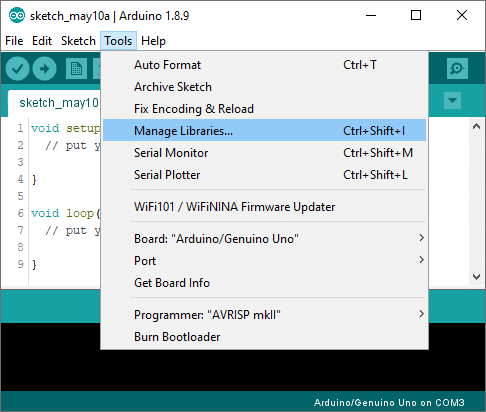
Another option is to navigate to Tools > Manage Libraries… or type Ctrl + Shift + I on Windows. The Library Manager will open and update the list of installed libraries.
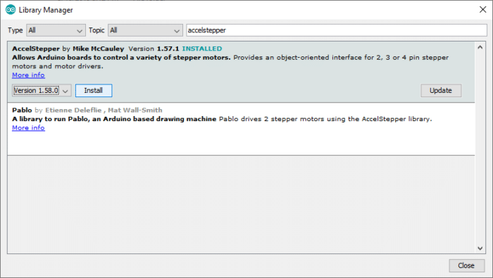
You can search for ‘accelstepper’ and look for the library by Mike McCauley. Select the latest version and then click Install.
AccelStepper example code
With the following sketch you can add acceleration and deceleration to the movements of the stepper motor, without any complicated coding. In the following example, the motor will run back and forth with a speed of 1000 steps per second and an acceleration of 500 steps per second squared.
Note that I am still using the driver in 1/8 microstepping mode. If you are using a different setting, play around with the speed and acceleration settings.
/* Example sketch to control a stepper motor with TB6560 stepper motor driver, AccelStepper library and Arduino: acceleration and deceleration. More info: https://www.makerguides.com */

// Include the AccelStepper library:
#include "AccelStepper.h"

// Define stepper motor connections and motor interface type. Motor interface type must be set to 1 when using a driver:
#define dirPin 2
#define stepPin 3
#define motorInterfaceType 1

// Create a new instance of the AccelStepper class:
AccelStepper stepper = AccelStepper(motorInterfaceType, stepPin, dirPin);

void setup() {
  // Set the maximum speed and acceleration:
  stepper.setMaxSpeed(1000);
  stepper.setAcceleration(500);
}

void loop() {
  // Set the target position:
  stepper.moveTo(8000);
  // Run to target position with set speed and acceleration/deceleration:
  stepper.runToPosition();

  delay(1000);

  // Move back to zero:
  stepper.moveTo(0);
  stepper.runToPosition();

  delay(1000);
}
Code explanation:
The first step is to include the library with #include <AccelStepper.h>.
// Include the AccelStepper library:
#include "AccelStepper.h"
The next step is to define the TB6560 to Arduino connections and the motor interface type. The motor interface type must be set to 1 when using a step and direction driver. You can find the other interface types here.
// Define stepper motor connections and motor interface type. Motor interface type must be set to 1 when using a driver:
#define dirPin 2
#define stepPin 3
#define motorInterfaceType 1
Next, you need to create a new instance of the AccelStepper class with the appropriate motor interface type and connections.
In this case I called the stepper motor ‘stepper’ but you can use other names as well, like ‘z_motor’ or ‘liftmotor’ etc. AccelStepper liftmotor = AccelStepper(motorInterfaceType, stepPin, dirPin);. The name that you give to the stepper motor will be used later to set the speed, position, and acceleration for that particular motor. You can create multiple instances of the AccelStepper class with different names and pins. This allows you to easily control 2 or more stepper motors at the same time.
// Create a new instance of the AccelStepper class:
AccelStepper stepper = AccelStepper(motorInterfaceType, stepPin, dirPin);
In the setup(), besides the maximum speed, we need to define the acceleration/deceleration. For this we use the function setMaxSpeed() and setAcceleration().
void setup() {
  // Set the maximum speed and acceleration:
  stepper.setMaxSpeed(1000);
  stepper.setAcceleration(500);
}
In the loop section of the code, we let the motor rotate a predefined number of steps. The function stepper.moveTo() is used to set the target position (in steps). The function stepper.runToPostion() moves the motor (with acceleration/deceleration) to the target position and blocks until it is at the target position. Because this function is blocking, you shouldn’t use this when you need to control other things at the same time.
  // Set the target position:
  stepper.moveTo(8000);
  // Run to target position with set speed and acceleration/deceleration:
  stepper.runToPosition();
If you would like to see more examples for the AccelStepper libary, check out my tutorial for the A4988 stepper motor driver:
Conclusion
In this article I have shown you how to control a stepper motor with the TB6560 stepper motor driver and Arduino. I hope you found it useful and informative. If you did, please share it with a friend who also likes electronics and making things!
I would love to know what projects you plan on building (or have already built) with this driver. If you have any questions, suggestions, or if you think that things are missing in this tutorial, please leave a comment down below.
Note that comments are held for moderation to prevent spam.
Benne is professional Systems Engineer with a deep expertise in Arduino and a passion for DIY projects.
Rajiv B
Thursday 25th of February 2021
Hi, How to stop the stepper motor while its rotating in between ? Any HIGH/LOW BRAKE signal on any pin that i can control ? Very nice post, BTW. Rajiv.
Rajiv B
Saturday 6th of March 2021
Ok...i figured this one out...the EN+ is not connected, actually its Active LOW, so its enabled forever by keeping it unconnected.
We need to control EN+ signal to STOP in between clockwise/ anticlockwise rotation. I connected EN+ to pin 8 & EN- to GND on Arduino Uno. In the Init part, we make it Digital output pin & set it LOW, so that its Enabled. Now, in between we pull it HIGH for some time & we can see the stepper NEMA17 stops, for that 'some' time, and after that resumes its motion.
I think, its a nice exercise left for the viewer to try, by Author.
Below is my code:
#define dirPin 5 #define stepPin 2 #define enPin 8 #define stepsPerRevolution 3200 int cntr =0;
void setup() { // Declare pins as output: pinMode(stepPin, OUTPUT); pinMode(dirPin, OUTPUT); pinMode(enPin, OUTPUT); digitalWrite(enPin, LOW); delay(5000); } void loop() { cntr =0; // Set the spinning direction clockwise: digitalWrite(dirPin, HIGH); // Spin the stepper motor 1 revolution slowly: for (int i = 0; i < stepsPerRevolution; i++) { // These four lines result in 1 step: digitalWrite(stepPin, HIGH); delayMicroseconds(500); digitalWrite(stepPin, LOW); delayMicroseconds(500); cntr +=1; digitalWrite(enPin, LOW); if (cntr == 1599) { digitalWrite(enPin, HIGH); delay(2000); digitalWrite(enPin, LOW); } } cntr =0; delay(5000); // Set the spinning direction counterclockwise: digitalWrite(dirPin, LOW); // Spin the stepper motor 1 revolution quickly: for (int i = 0; i < stepsPerRevolution; i++) { // These four lines result in 1 step: digitalWrite(stepPin, HIGH); delayMicroseconds(500); digitalWrite(stepPin, LOW); delayMicroseconds(500); cntr +=1; if (cntr == 1599) { digitalWrite(enPin, HIGH); delay(2000); digitalWrite(enPin, LOW); } } delay(5000); }
John
Tuesday 23rd of February 2021
Very clear and precise, a good introduction to steppers and how they work. Setting up the tb6560 was straight forward with your guide thanks for the hard work and clear thoughts.
best John
Ray
Thursday 18th of February 2021
Hello! I'm trying to make a fritzing diagram but I cannot find an .fzpz for the TB6560 motor driver. Where did you find it? Did you make it yourself?
Thanks in advance!
Benne de Bakker
Tuesday 2nd of March 2021
Hi Ray, Yes, I made it myself, you can also just load a picture into Fritzing and use that as a part if you only want to draw a wiring schematic. Benne
Eduardo Saman
Saturday 2nd of January 2021
Very good explanation, I just discovered an excellent site, thank you.
Doug
Thursday 11th of June 2020
Thanks for posting these instructions. I have a 4 axis CNC and the 4th axis/driver was not working. I was able to quickly hook up an Arduino Pro Mini and test it with your sketch and show it worked. BTW, you don't need to bind the grounds between 24V input and the Arduino inputs. The opto-isolators work off the 5V input and the active-Low signal of the Step/Direction/Enable lines.
My problem ended up being the CNC put out 5.3V and my 3.3V ESP32 was not going high enough to turn off the Opto-isolators. A quick hack was to put a diode inline with the 5.3V making it 4.6V and that was enough for the 3.3V signal to turn off the opto-isolators. But I wouldn't have known to keep looking without your post to prove the driver was functioning. Thank you.