In this tutorial, you will learn how you can control TM1637 4-digit 7-segment displays with Arduino. These displays are fantastic for displaying sensor data, temperature, time, etc.
I have included 3 examples in this tutorial. In the first example, we will look at the basic functions of the TM1637Display library. In the second example, I will show you how you can display the time on a 4-digit display. The last example can be used to create a simple temperature display in combination with the DHT11.
Wiring diagrams are also included. After the example, I break down and explain how the code works, so you should have no problems modifying it to suit your needs.
If you have any questions, please leave a comment below.
For more display tutorials, check out the articles below:
Supplies
Hardware components
Software
Makerguides.com is a participant in the Amazon Services LLC Associates Program, an affiliate advertising program designed to provide a means for sites to earn advertising fees by advertising and linking to products on Amazon.com. As an Amazon Associate we earn from qualifying purchases.
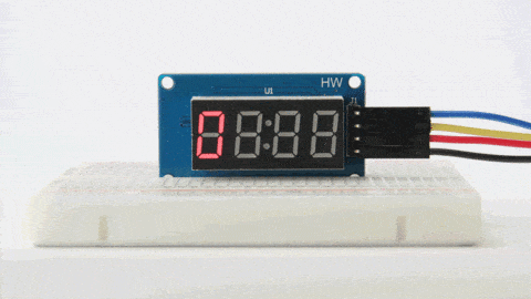
Information about the display
Bare 4-digit 7-segment displays usually require 12 connection pins. That’s quite a lot and doesn’t leave much room for other sensors or modules. Thanks to the TM1637 IC mounted on the back of the display module, this number can be reduced to just four. Two pins are required for the power connections and the other two pins are used to control the segments.
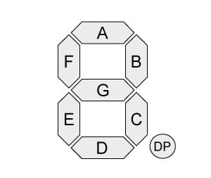
7-segment displays contain 7 (or 8) individually addressable LEDs. The segments are labeled A to G and some displays also have a dot (the 8th LED). Use this image as a reference when setting the individual segments in the code later.
You can buy many different display modules that use a TM1637 IC. The color, size, dots, and connection points can all be different. I don’t have experience with all the different versions of this display but as long as they use the TM1637, the code examples provided below should work.
Here you can find the basic specifications of the display module that I used in this tutorial.
TM1637 4-Digit 7-Segment Display Specifications
| Operating voltage | 3.3 – 5 V |
| Current draw | 80 mA |
| Luminance levels | 8 |
| Display dimensions | 30 x 14 mm (0.36″ digits) |
| Overall dimensions | 42 x 24 x 12 mm |
| Hole dimensions | 38 x 20, ⌀ 2.2 mm |
| Operating temperature | -10 – 80 °C |
| Cost | Check price |
The TM1637 IC is made by Titan Micro Electronics. For more information, you can check out the datasheet below:
Wiring – Connecting TM1637 4-digit 7-segment display to Arduino UNO
Connecting the display to an Arduino or other microcontroller is super easy. You only need to connect 4 wires: 2 for power and 2 to transfer the data.
The wiring diagram below shows you how you can connect the display to the Arduino.
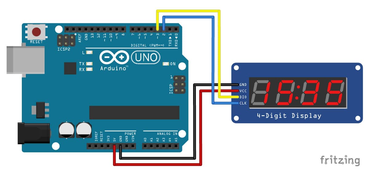
The connections are also given in the table below:
TM1637 Display Connections
| TM1637 4-Digit Display | Arduino |
|---|---|
| VCC | 5 V |
| GND | GND |
| CLK | Digital pin 2 |
| DIO | Digital pin 3 |
Note that the order and location of the pins can be different depending on the manufacturer!
For this tutorial, I connected CLK and DIO to pin 2 and 3 respectively, but you can change this to any of the digital pins you want. You just have to change the pin configuration in the code accordingly.
TM1637 4-digit 7-segment display Arduino example code
Avishay Orpaz has written an excellent library for TM1637 displays, the TM1637Display library. This library has several built-in functions that make controlling the display fairly easy.
The main functions include:
- setSegments() – Set the raw value of the segments of each digit
- showNumberDec() – Display a decimal number
- showNumberDecEx() – Display a decimal number with decimal points or colon
- setBrightness() – Set the brightness of the display
- clear() – Clear the display
The code example below features all of these functions. I will explain how each function can be used in more detail below.
You can upload the example code to your Arduino using the Arduino IDE.
To install the library, you can download it as a .zip from GitHub here. Next, go to Sketch > Include Library > Add .ZIP Library… in the Arduino IDE.
Another option is to navigate to Tools > Manage Libraries… or type Ctrl + Shift + I on Windows. The Library Manager will open and update the list of installed libraries.
You can search for ‘tm1637’ and look for the library by Avishay Orpaz. Select the latest version and then click Install.
Example code
You can copy the code by clicking the button in the top right corner of the code field.
/* Example code for TM1637 4 digit 7 segment display with Arduino. More info: www.www.makerguides.com */

// Include the library:
#include "TM1637Display.h"

// Define the connections pins:
#define CLK 2
#define DIO 3

// Create display object of type TM1637Display:
TM1637Display display = TM1637Display(CLK, DIO);

// Create array that turns all segments on:
const uint8_t data[] = {0xff, 0xff, 0xff, 0xff};

// Create array that turns all segments off:
const uint8_t blank[] = {0x00, 0x00, 0x00, 0x00};

// You can set the individual segments per digit to spell words or create other symbols:
const uint8_t done[] = {
  SEG_B | SEG_C | SEG_D | SEG_E | SEG_G,           // d
  SEG_A | SEG_B | SEG_C | SEG_D | SEG_E | SEG_F,   // O
  SEG_C | SEG_E | SEG_G,                           // n
  SEG_A | SEG_D | SEG_E | SEG_F | SEG_G            // E
};

// Create degree Celsius symbol:
const uint8_t celsius[] = {
  SEG_A | SEG_B | SEG_F | SEG_G,  // Circle
  SEG_A | SEG_D | SEG_E | SEG_F   // C
};

void setup() {
  // Clear the display:
  display.clear();
  delay(1000);
}

void loop() {
  // Set the brightness:
  display.setBrightness(7);
  // All segments on:
  display.setSegments(data);

  delay(1000);
  display.clear();
  delay(1000);

  // Show counter:
  int i;
  for (i = 0; i < 101; i++) {
    display.showNumberDec(i);
    delay(50);
  }

  delay(1000);
  display.clear();
  delay(1000);

  // Print number in different locations, loops 2 times:
  int j;
  for (j = 0; j < 2; j++) {
    for (i = 0; i < 4; i++) {
      display.showNumberDec(i, false, 1, i);
      delay(500);
      display.clear();
    }
  }

  delay(1000);
  display.clear();
  delay(1000);

  // Set brightness (0-7):
  int k;
  for (k = 0; k < 8; k++) {
    display.setBrightness(k);
    display.setSegments(data);
    delay(500);
  }

  delay(1000);
  display.clear();
  delay(1000);

  // Print 1234 with the center colon:
  display.showNumberDecEx(1234, 0b11100000, false, 4, 0);

  delay(1000);
  display.clear();
  delay(1000);

  int temperature = 24;
  display.showNumberDec(temperature, false, 2, 0);
  display.setSegments(celsius, 2, 2);

  delay(1000);
  display.clear();
  delay(1000);

  display.setSegments(done);
  while(1);
}
How the code works:
The code starts with including the library. Make sure that you have the correct library installed, otherwise you will get an error message while compiling the code.
// Include the library:
#include "TM1637Display.h"
The next step is to specify the connection pins. The statement #define is used to give a name to a constant value. The compiler will replace any references to this constant with the defined value when the program is compiled. So everywhere you mention CLK, the compiler will replace it with the value 2 when the program is compiled.
// Define the connections pins:
#define CLK 2
#define DIO 3
Initiate Display
Next, we create a display object of the type TM1637Display with the defined CLK and DIO pins. Note that I called the display ‘display’, but you can use other names as well like ‘temperature_display’.
The name that you give to the display will be used later to write data to that particular display. You can create and control multiple display objects with different names and connection pins. There currently is no limit in the library.
// Create display object of type TM1637Display:
TM1637Display display = TM1637Display(CLK, DIO);

// You can create more than one display object. Give them different names and connection pins:
TM1637Display display_1  = TM1637Display(2, 3);
TM1637Display display_2  = TM1637Display(4, 5);
TM1637Display display_3  = TM1637Display(6, 7);
There are several ways to control the individual segments of the display. Before the setup section of the code, I specified several arrays to set the individual display segments. We will use the function setSegments() later to write them to the display.
The first option is to write hexadecimal numbers to the display for each digit. The hexadecimal 0xff translates to 11111111 in binary, this sets all the segments on (including the dot if your display has one). 0xef for example, translates to 11101111. This would set all the segments on, except for segment E. Note that counting goes from right to left, so 11111111 corresponds to segments (dot)GFEDCBA.
// Create array that turns all segments on:
const uint8_t data[] = {0xff, 0xff, 0xff, 0xff};

// Create array that turns all segments off:
const uint8_t blank[] = {0x00, 0x00, 0x00, 0x00};
The library has a function built-in that makes setting individual segments a bit easier. See the code snippet below. You can create arrays to spell words. Each segment is separated by a | and digits of the display are separated by a comma.
// You can set the individual segments per digit to spell words or create other symbols:
const uint8_t done[] = {
  SEG_B | SEG_C | SEG_D | SEG_E | SEG_G,           // d
  SEG_A | SEG_B | SEG_C | SEG_D | SEG_E | SEG_F,   // O
  SEG_C | SEG_E | SEG_G,                           // n
  SEG_A | SEG_D | SEG_E | SEG_F | SEG_G            // E
};
Setup function
You can leave the setup section of the code empty if you want. I just used the function clear() to ensure that the display was cleared.
void setup() {
  // Clear the display:
  display.clear();
  delay(1000);
}
Loop function
In the loop section of the code, I show several examples of the different library functions:
setSegments(segments[ ], length, position)
This function can be used to set the individual segments of the display. The first argument is the array that includes the segment information. The second argument specifies the number of digits to be modified (0-4). If you want to spell dOnE, this would be 4, for a °C symbol, this would be 2. The third argument sets the position from which to print (0 – leftmost, 3 – rightmost). So if you want to print a °C symbol on the third and fourth digit, you would use:
// Create degree Celsius symbol:
const uint8_t celsius[] = {
  SEG_A | SEG_B | SEG_F | SEG_G,  // Circle
  SEG_A | SEG_D | SEG_E | SEG_F   // C
};

display.setSegments(celsius, 2, 2);
The second and third argument of the function can also be omitted.
showNumberDec(number, leading_zeros, length, position)
This is probably the function that you will use the most. The first argument is a number that you want to display on the screen. The rest of the arguments are optional.
The second argument can be used to turn on or off leading zeros. 10 without leading zeros would print as __10 and with leading zeros as 0010. You can turn them on by setting this argument as true or turn them off by setting it as false. NOTE: leading zero is not supported with negative numbers.
The third and fourth argument are the same as in the previous function.
// Print the number 12 without leading zeros on the second and third digit:
display.showNumberDec(12, false, 2, 1);
showNumberDecEx(number, dots, leading_zeros, length, position)
This function allows you to control the dots of the display. Only the second argument is different from the showNumberDec function. It allows you to set the dots between the individual digits.
You can use the following values.
For displays with dots between each digit use
- 0b10000000 – 0.000
- 0b01000000 – 00.00
- 0b00100000 – 000.0
- 0b11100000 – 0.0.0.0
for displays with just a colon use
- 0b01000000 – 00:00
and for displays with dots and colons colon use
- 0b11100000 – 0.0:0.0
So if you want to display a clock with center colon on (see clock example below), you would use something like:
// Print 1234 with the center colon:
display.showNumberDecEx(1234, 0b11100000, false, 4, 0);
setBrightness(brightness, true/false)
This function sets the brightness of the display (as the name suggests). You can specify a brightness level from 0 (lowest brightness) to 7 (highest brightness). The second parameter can be used to turn the display on or off, false means off.
// Set the display brightness (0-7):
display.setBrightness(7);
Clock example: TM1637 4-digit 7-segment display with DS3231 RTC
One of the typical uses for a 4-digit 7-segment display is to show the time. By combining the TM1637 with a real time clock module (RTC), you can easily create a 24-hour clock.
In this example I used this commonly used DS3231 RTC module.
This module communicates with the Arduino via I2C, so you only need two connections to read the time.
The wiring diagram below shows you how you can connect the DS3231 RTC to the Arduino. Note that the TM1637 display is connected in the same way as before.
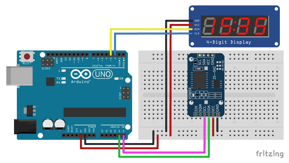
The connections are also given in the table below:
DS3231 RTC Connections
| DS3231 | Arduino |
|---|---|
| VCC | 5 V |
| GND | GND |
| SDA | A4 |
| SCL | A5 |
The following code example can be used to display the time in a 24-hour time format. If your display has a center colon, then this code will make it blink. You can also disable this by removing the last few lines of code.
The first time you upload the code, the RTC will be set to the time that the sketch was compiled.
You can install a coin cell battery on the back of the module, so the time is stored in case it loses power. Apparently the charging circuit of most Chinese modules can possibly overcharge the coin cell battery, so you might want to buy a DS3231 module from Adafruit instead.
The code uses the Adafruit RTC library, which you can download here on GitHub. You can also install it via the Library Manager in the Arduino IDE by searching for ‘RTClib’, or click the download button below:
Example code
/* Arduino example code to display a 24 hour time format clock on a
  TM1637 4 digit 7 segment display with a DS32321 RTC.
  More info: www.www.makerguides.com */

// Include the libraries:
#include "RTClib.h"
#include "TM1637Display.h"

// Define the connections pins:
#define CLK 2
#define DIO 3

// Create rtc and display object:
RTC_DS3231 rtc;
TM1637Display display = TM1637Display(CLK, DIO);

void setup() {
  // Begin serial communication at a baud rate of 9600:
  Serial.begin(9600);
  // Wait for console opening:
  delay(3000);

  // Check if RTC is connected correctly:
  if (!rtc.begin()) {
    Serial.println("Couldn't find RTC");
    while (1);
  }
  // Check if the RTC lost power and if so, set the time:
  if (rtc.lostPower()) {
    Serial.println("RTC lost power, lets set the time!");
    // The following line sets the RTC to the date & time this sketch was compiled:
    rtc.adjust(DateTime(F(__DATE__), F(__TIME__)));
    // This line sets the RTC with an explicit date & time, for example to set
    // January 21, 2014 at 3am you would call:
    //rtc.adjust(DateTime(2014, 1, 21, 3, 0, 0));
  }

  // Set the display brightness (0-7):
  display.setBrightness(5);
  // Clear the display:
  display.clear();
}

void loop() {
  // Get current date and time:
  DateTime now = rtc.now();

  // Create time format to display:
  int displaytime = (now.hour() * 100) + now.minute();

  // Print displaytime to the Serial Monitor:
  Serial.println(displaytime);

  // Display the current time in 24 hour format with leading zeros enabled and a center colon:
  display.showNumberDecEx(displaytime, 0b11100000, true);

  // Remove the following lines of code if you want a static instead of a blinking center colon:
  delay(1000);

  display.showNumberDec(displaytime, true); // Prints displaytime without center colon.

  delay(1000);
}
Thermometer example: TM1637 4-digit 7-segment display with DHT11 temperature and humidity sensor
4-Digit 7-segment displays are great for displaying sensor readings like temperature, humidity, voltage or speed. In the following example, I will show you how you can display temperature readings on the TM1637 display.
We will be using the popular DHT11 temperature and humidity sensor.
The wiring diagram below shows you how you can connect the DHT11 sensor in combination with the TM1637 display to the Arduino.
Note that the TM1637 display is connected in the same way as before.
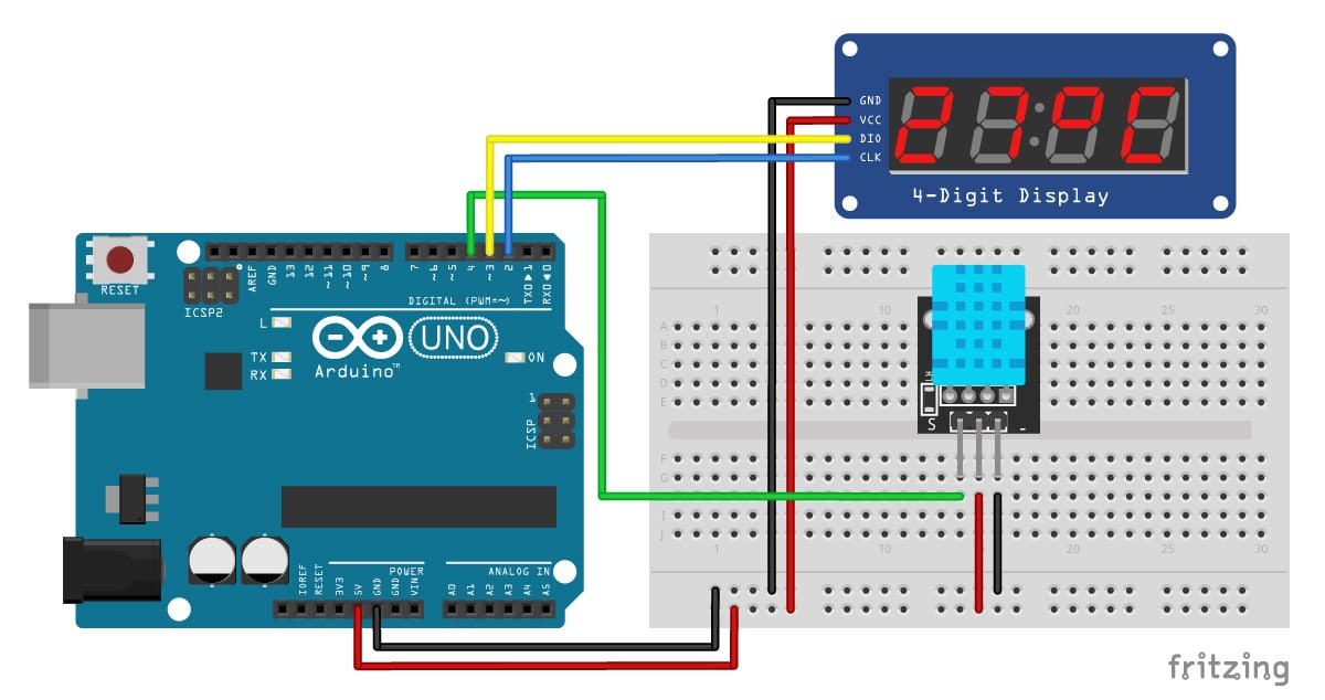
The connections are also given in the table below:
DHT11 Connections
| DHT11 | Arduino |
|---|---|
| + | 5 V |
| – | GND |
| s | Digital pin 4 |
Note that the order of the pins can be different, depending on the manufacturer.
If you would like to use a 4 pin sensor, check out my tutorial for the DHT11 and DHT22 temperature and humidity sensors.
The example code below can be used to display the temperature readings on the display. It alternates between the temperature in Celius and Fahrenheit, both are shown for 2 seconds.
The function setSegments() is used to display the Celsius and Fahrenheit symbols.
The code uses the Adafruit DHT sensor library which you can download here on GitHub. This library only works if you also have the Adafruit Unified Sensor library installed, which is also available on GitHub.
You can also download the two libraries by clicking on the buttons below:
For more information see my DHT11 with Arduino tutorial.
Example code
/* Arduino example sketch to display DHT11 temperature readings
  on a TM1637 4-digit 7-segment display.
  More info: www.www.makerguides.com */

// Include the libraries:
#include "TM1637Display.h"
#include "Adafruit_Sensor.h"
#include "DHT.h"

// Define the connections pins:
#define CLK 2
#define DIO 3
#define DHTPIN 4

// Create variable:
int temperature_celsius;
int temperature_fahrenheit;

// Create degree Celsius symbol:
const uint8_t celsius[] = {
  SEG_A | SEG_B | SEG_F | SEG_G,  // Circle
  SEG_A | SEG_D | SEG_E | SEG_F   // C
};

// Create degree Fahrenheit symbol:
const uint8_t fahrenheit[] = {
  SEG_A | SEG_B | SEG_F | SEG_G,  // Circle
  SEG_A | SEG_E | SEG_F | SEG_G   // F
};

// Set DHT type, uncomment whatever type you're using!
#define DHTTYPE DHT11   // DHT 11
//#define DHTTYPE DHT22   // DHT 22  (AM2302)
//#define DHTTYPE DHT21   // DHT 21 (AM2301)

// Create display object of type TM1637Display:
TM1637Display display = TM1637Display(CLK, DIO);
// Create dht object of type DHT:
DHT dht = DHT(DHTPIN, DHTTYPE);

void setup() {
  // Set the display brightness (0-7):
  display.setBrightness(0);
  // Clear the display:
  display.clear();
  // Setup sensor:
  dht.begin();
  // Begin serial communication at a baud rate of 9600:
  Serial.begin(9600);
  // Wait for console opening:
  delay(2000);
}

void loop() {
  // Read the temperature as Celsius and Fahrenheit:
  temperature_celsius = dht.readTemperature();
  temperature_fahrenheit = dht.readTemperature(true);
  // Print the temperature to the Serial Monitor:
  Serial.println(temperature_celsius);
  Serial.println(temperature_fahrenheit);

  // Show the temperature on the TM1637 display:
  display.showNumberDec(temperature_celsius, false, 2, 0);
  display.setSegments(celsius, 2, 2);

  delay(2000);

  display.showNumberDec(temperature_fahrenheit, false, 2, 0);
  display.setSegments(fahrenheit, 2, 2);

  delay(2000);
}
Conclusion
In this article I have shown you how you can use a TM1637 4-digit 7-segment display with Arduino. We also looked at a clock and thermometer example. I hope you found it useful and informative. If you did, please share it with a friend who also likes electronics and making things!
I really like to use these displays to show sensor readings or things like the speed of a motor. With the TM1637Display library, programming the displays becomes very easy, so there is no reason you shouldn’t incorporate one in your next project.
I would love to know what projects you plan on building (or have already built) with this display. If you have any questions, suggestions, or if you think that things are missing in this tutorial, please leave a comment down below.
Note that comments are held for moderation to prevent spam.
Benne is professional Systems Engineer with a deep expertise in Arduino and a passion for DIY projects.
Pavel
Friday 1st of December 2023
Can you please fix missing library names in include statements? Thank you so much for this tutorial.
Pavel
Sunday 3rd of December 2023
@Stefan Maetschke, Thank you Stefan, it all looks good now. Thank you very much for this high quality easy to follow tutorial.
Stefan Maetschke
Friday 1st of December 2023
@Pavel, there is an issue with the syntax highlighter, which I fixed but I don't see any missing library names. Which ones are missing? Thanks Stefan
Bryan
Wednesday 14th of June 2023
#include #include #include #include
LiquidCrystal_I2C lcd(0x27,16,2);
// Pin yang terhubung dengan keypad const byte ROWS = 4; // jumlah baris pada keypad const byte COLS = 4; // jumlah kolom pada keypad char keys[ROWS][COLS] = { {'1','2','3','A'}, {'4','5','6','B'}, {'7','8','9','C'}, {'*','0','#','D'} }; byte rowPins[ROWS] = {9, 8, 7, 6}; // pin baris keypad terhubung ke pin Arduino byte colPins[COLS] = {5, 4, 3, 2}; // pin kolom keypad terhubung ke pin Arduino Keypad keypad = Keypad(makeKeymap(keys), rowPins, colPins, ROWS, COLS);
// Pin yang terhubung dengan 4 Digit seven segment TM1637 #define CLK_PIN 10 #define DIO_PIN 11 TM1637Display display(CLK_PIN, DIO_PIN);
const String PASSWORD = "1234"; // Password yang benar String enteredPassword = ""; // Password yang diinput
void setup() { lcd.begin();
lcd.print("Masukkan Password");
display.setBrightness(0x0f); // Atur kecerahan TM1637
updateDisplay(); }
void loop() { char key = keypad.getKey();
if (key) { if (key == '#') { // Tombol "#" ditekan if (enteredPassword == PASSWORD) { lcd.clear(); lcd.print("Password OK"); } else { lcd.clear(); lcd.print("Password NOT OK"); } delay(2000); lcd.clear(); enteredPassword = ""; } else if (key == '*') { // Tombol "*" ditekan enteredPassword = ""; } else { // Tombol angka ditekan if (enteredPassword.length() < 4) { enteredPassword += key; } }
updateDisplay(); } }
void updateDisplay() { // Mengupdate tampilan TM1637 display.showNumberDec(atoi(enteredPassword.c_str()), true, 4, 0); }
Reza
Monday 17th of May 2021
Thanks a lot for posting, this really helped me understanding how to control the display
stephen
Tuesday 20th of April 2021
I did a few changes but it work just fine good job :)
Ricky
Tuesday 16th of February 2021
Hello, The project is very nice. I used it with MLX90614 but could not display the third digit with a decimal. Have you tried doing this with three digit thermometer decimal point?