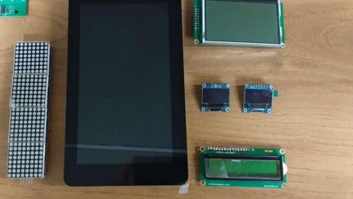
In this article, I will provide the essential details about the Top 7 Arduino compatible displays that are widely used with Arduino boards.
I will also discuss the interfacing of these displays with Arduino, and provide links to more in-depth articles that we have on each type of display.
We’ll discuss the pros and cons of each type of display, and what situations they are best suited for so that you can select the best display for your Arduino project.
Hardware components
| Arduino Uno Rev3 | x1 | Amazon |
| Arduino Mega (Optional) | x1 | Amazon |
| 16 x 2 LCD Display | x1 | Amazon |
| GLCD Display | x1 | Amazon |
| Seven-Segment Display | x1 | Amazon |
| OLED Display | x1 | Amazon |
| TFT LCD Display | x1 | Amazon |
| TFT Touchscreen LCD Display | x1 | Amazon |
| Dot-matrix Display | x1 | Amazon |
| Breadboard | x1 | Amazon |
| Jumper wires | x15 | Amazon |
| 10K Potentiometer | x1 | Amazon |
| USB cable type A/B | x1 | Amazon |
Software
| Arduino IDE | Arduino IDE |
Makerguides.com is a participant in the Amazon Services LLC Associates Program, an affiliate advertising program designed to provide a means for sites to earn advertising fees by advertising and linking to products on Amazon.com.
An Arduino display can serve a variety of purposes. Since micro controllers usually read data from sensors, a display allows you to see this information in real-time without needing to use the serial monitor within the Arduino IDE.
But there are different types of displays that you can use, and they each have theirs pros and cons.
1. Liquid Crystal Display
LCD screens(Liquid Crystals Display) are widespread electronics displays in various devices.
Although these LCDs are available in various sizes (16×1, 16×2, 20×4, etc.), they all share the same Hitachi LCD controller HD44780 so you can swap them easily.
It can display 16 characters on each line in a 5×7 pixel matrix. This LCD is capable of displaying 224 different characters.
Command and Data Registers are present on this LCD. The command register and Data register store various values are given to the display.
To control the display, you must put the data from the image in the data register and instructions in the instruction registers.
In your Arduino project, Liquid Crystal Library simplifies this, so you don’t need to know the low-level instructions.
You can vary the brightness using the potentiometer to be connected across the VEE pin.
Can an Arduino run an LCD display?
These LCDs can be controlled using two modes:
- 4-bit mode
- 8-bit mode
The 4-bit mode requires seven I/O pins from the Arduino, while the 8-bit mode requires 11 pins. For displaying on the screen, you can do most everything in a 4-bit way. It benefits you.
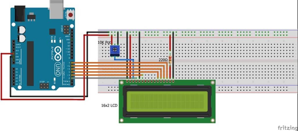
Wiring 16×2 LCD with Arduino UNO
This circuit diagram is self-explanatory. Most of Arduino’s projects use 4-bit mode. Because of that, it saves the Arduino Pins.
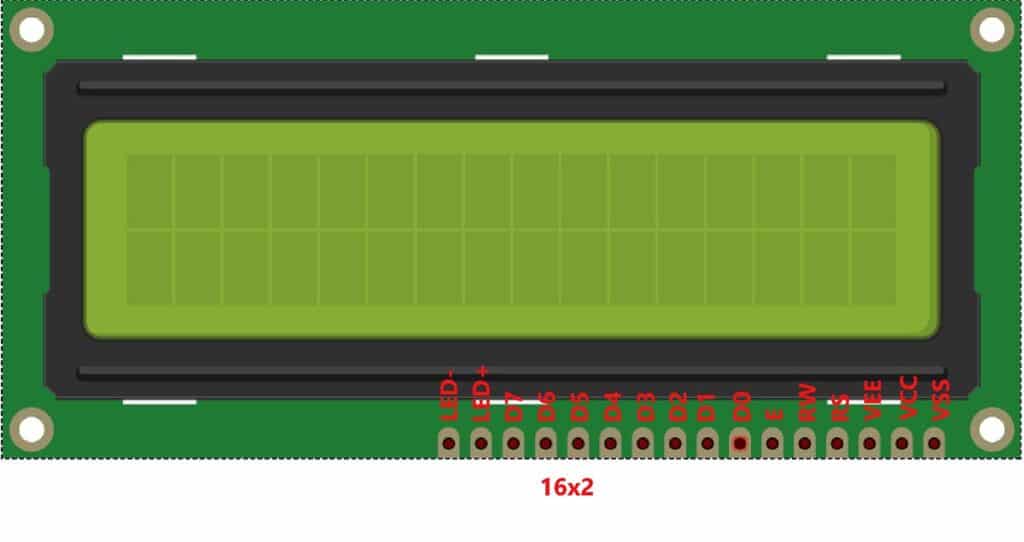
The standard LCD pinout is given in the table below:
| Pin no. | Pin Name | Arduino Connection | Pin Description |
| 1 | VSS | GND | Signal ground |
| 2 | VCC | 5 V | Logic power for LCD |
| 3 | VEE/VO | 10 kΩ Potentiometer | Contrast adjustment |
| 4 | RS | Pin 2 | Register select |
| 5 | R/W | GND | Read/write |
| 6 | E | Pin 3 | Enable Operation |
| 7 to 14 | D0 – D7 | — | Data bus lines used for 8-bit mode |
| 11 to 14 | D4 – D7 | Pin 4 – 7 | Data bus lines used for 4-bit mode |
| 15 | LED+ | 5 V | Anode for LCD backlight |
| 16 | LED- | GND | Cathode for LCD backlight |
We have a whole in-depth guide to learn more about the 16×2 LCD, so head over to our 16×2 LCD tutorial for more info on this display. If you’re interested in learning more about controlling a character I2C LCD with Arduino then check out the in-depth tutorial we have on this display type.
2. Graphical Liquid Crystal Display
The Graphical LCD (GLCD) is entirely different from ordinary LCD. Ordinary LCDs can only display simple text or numbers within a fixed size.
The GLCD has 128 * 64, equal to 8192 dots or 8192/8 = 1024 pixels, so apart from characters, you can display any graphical image, string, or character on this GLCD.
There are three different ways you can interface the GLCD with Arduino.
- 4-bit Parallel Mode
- 8-bit Parallel Mode
- Serial Mode
Many types of GLCD controllers are available in the market, like KS0108, SSD1306, ST7920, SH1106, and SSD1322.
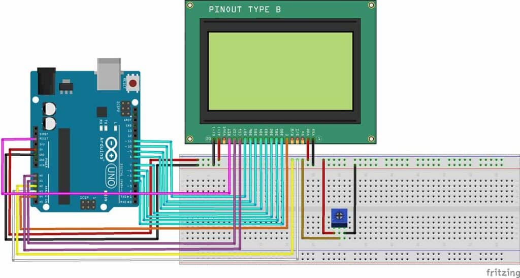
Wiring 128×64 Graphical LCD with Arduino UNO
128×64 Graphical LCD Display Pinout is given in the table below:
| Pin no. | Pin Name | Arduino Connection | Pin Description |
| 1 | GND | GND | Ground |
| 2 | VCC | +5V | Supply Voltage |
| 3 | VO | 10 kΩ Potentiometer | Contrast Adjust |
| 4 | RS | Pin A3 | Register Select |
| 5 | RW | Pin A2 | Read / Write Control (Serial Data In) |
| 6 | E | Pin A4 | Enable (Serial CLK) |
| 7-14 | DB0 – DB7 | Pin 4- 11 | Data |
| 15 | CS1 | PIn A0 | Chip select for IC1 |
| 16 | CS2 | Pin A1 | Chip select for IC2 |
| 17 | RST | RESET | Reset |
| 18 | NC /VEE | NC | Not Connected /LCD Negative Voltage |
| 19 | A | 5 V | Backlight LED Anode |
| 20 | K | GND | Backlight LED Cathode |
For a full guide on using a graphical LCD with Arduino, check out our article: Interfacing 128 x 64 Graphical LCD with Arduino
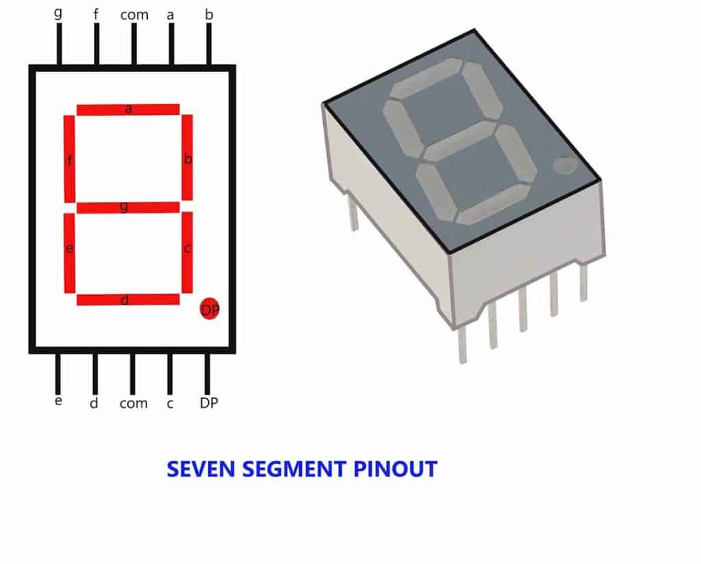
3. Seven-Segment Displays
A seven-segment display is a simple type of display. This display is the most common device for displaying digits (most of 0 – 9) and the alphabet.
Some displays can also show characters and images.
LEDs (Light-emitting diodes) or LCDs in seven-segment displays made it.
These displays contain 7-segments, and an extra 8th segment is used to display dots.
These seven-segment display circuit diagrams are shown below:
There are two types of seven-segment displays available in the market. According to the type of application, these displays can be used.
- Common Anode Display
- Common Cathode Display
The most common electronic devices like microwave ovens, calculators, washing machines, radios, digital clocks, etc., display numeric information.
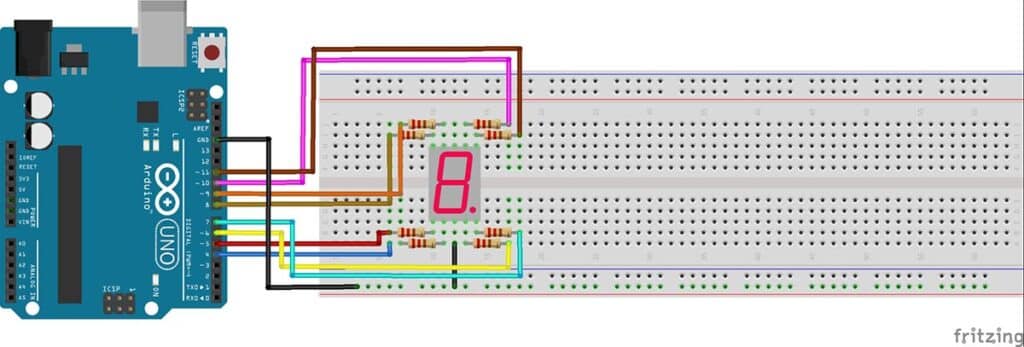
Wiring 7-Segment Display with Arduino UNO
7-Segment Display Pinout is given in the table below:
| Pin no. | Pin Name | Arduino Connection |
| 1 | a | Pin 4 |
| 2 | b | Pin 5 |
| 3 | c | Pin 6 |
| 4 | d | Pin 7 |
| 5 | e | Pin 8 |
| 6 | f | Pin 9 |
| 7 | g | Pin 10 |
| 8 | DP | Pin 11 |
Read our TM1637 Seven-Segment Display article for more detailed information about using this type of display.
4. OLED Displays
The organic light-emitting diode (OLED) is a tiny screen meaning 0.96 inch OLED display module.
This Display is super-light, almost paper-thin, flexible, and produces a crisper picture.
Drivers for OLED displays such as SSD1306 and SH1106 differ in communication interfaces, size, and colors. But, the SSD1306 controller’s versatility.
- Communication interface: I2C, SPI
- Size: 128×64, 128×32 etc.
- Color: White, Blue, etc.
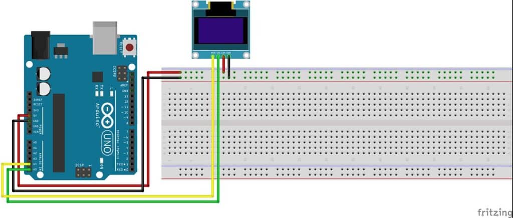
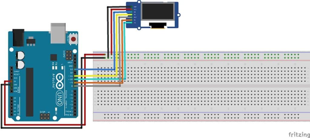
Wiring SSD1306 OLED with Arduino UNO
SSD1306 OLED Display Pinout is given in the table below:
| Pin no. | Pin Name | Arduino Connection | Pin Description |
| 1 | GND | GND | Ground |
| 2 | Supply (VDD, VCC,5V) | +5V | It can be powered by either 3.3V or 5V |
| 3 | SDA (D1, MOSI) | Pin 11 / Pin A4 | There is the data pin of both; it can either be used for I2C or SPI |
| 4 | SCK (D0, SCL, CLK) | Pin 13/ Pin A5 | The display supports both I2C and SPI, for which the clock is supplied through this pin |
| 5 | RES(RST, RESET) | Pin 8 | Reset module (SPI) |
| 6 | DC (A0) | Pin 9 | Data Command ( SPI) |
| 7 | Chip Select (CS) | Pin 10 | Chip select (SPI) |
Wiring SSD1306 OLED with Arduino UNO ( I2C )
Wiring SSD1306 OLED with Arduino UNO ( SPI )
See our full guide on how to use the SSD1306 OLED display with Arduino.
5. TFT LCD Display
TFT LCD is a variant type of LCD that uses Thin-film-transistor (TFT) technology to improve image qualities such as addressability and contrast.
A TFT LCD is an active-matrix LCD, in contrast to passive-matrix LCDs or simple, direct-driven LCDs with a few segments. Easy to Interfacing with a TFT LCD and Arduino.
You can start the display using the I2C and SPI communication interface between the Arduino and the TFT LCD.
In the market, various sizes of TFT LCD are available.
- 1.8” Display with a resolution of 160 x 128 Pixels.
- 2.0” Display with a resolution of 220 x 176 Pixels.
- 2.4” Display with a resolution of 320 x 240 Pixels.
- 2.8” Display with a resolution of 320 x 240 Pixels.
- 3.2” Display with a resolution of 400 x 240 Pixels.
- 3.5” Display with a resolution of 480 x 320 Pixels.
Wiring TFT LCD with Arduino UNO
The table below shows the 1.8 TFT wiring to Arduino UNO.
| Pin no. | Pin Name | Arduino Connection | Pin Description |
| 1 | SCK | Pin 13 | Clock line |
| 2 | SDA | Pin 11 | Data line |
| 3 | A0 or DC | Pin 9 | Data command |
| 4 | RESET | Pin 8 | Reset module |
| 5 | CS | Pin 10 | Chip Select |
| 6 | GND | GND | GND |
| 7 | VCC | 5 V | Supply Voltage |
| 8 | LED | 3.3V | Backlight |
For a more detailed guide on interfacing a TFT display with Arduino, check out our article about Interfacing a 1.8″ TFT colour TFT display with Arduino Uno.
6. TFT LCD Touchscreen Display
TFT touchscreen are fantastic graphical interfaces that can be used with different microcontrollers; they have good graphics and pixel mapping abilities.
It has touch capabilities and an SD card drive in the back; additionally, It can be plugged directly into an Arduino Board.
You can draw text, images, and shapes to the screen with the TFT library.
The 2.4″ TFT LCD module features a bright backlight(4 white LEDs), colorful 240×320 pixels display, and RGB pixel control for generator resolution than black and white displays.
It comes with a 2.4″ TFT LCD touchscreen with 320×240 pixels and 16-bit color. It also has a resistive touch screen, so you can easily detect your finger presses anywhere on the screen.
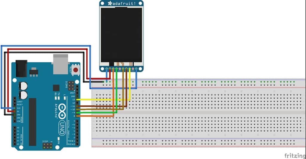
Wiring TFT Touch screen LCD with Arduino UNO
As with other display devices, the module has a simple Pin configuration.
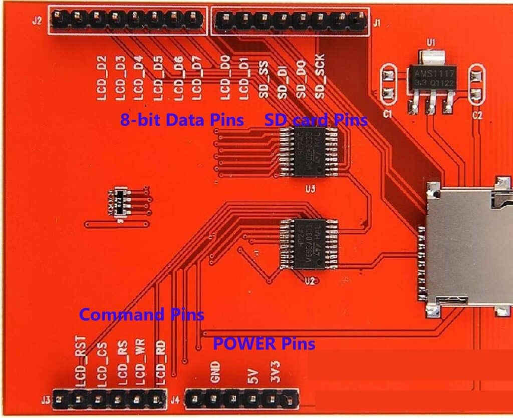
POWER Pins
| Pin no. | Pin Name | Arduino Connection | Pin Description |
| 1 | GND | GND | power GND |
| 2 | 5V | 5V | 5V power input |
| 3 | 3.3V | 3.3V | 3.3V power input, this pin can be disconnected |
Command Pins
| Pin no. | Pin Name | Arduino Connection | Pin Description |
| 1 | LCD_RD | Pin A0 | LCD bus read signal |
| 2 | LCD_WR | Pin A1 | LCD bus write signal |
| 3 | LCD_RS | Pin A2 | LCD bus command/data selection signallow level: command, high level: data |
| 4 | LCD_CS | Pin A3 | LCD bus chip select signal, low level enable |
| 5 | LCD_RST | Pin A4 | LCD bus reset signal, low-level reset |
SD Card Reader PIns
| Pin no. | Pin Name | Arduino Connection | Pin Description |
| 1 | SD_SCK | Pin 13 | SD card SPI bus clock signal |
| 2 | SD_D0 | Pin 12 | SD card SPI bus MISO signal |
| 3 | SD_D1 | Pin 11 | SD card SPI bus MOSI signal |
| 4 | SD_SS | Pin 10 | SD card SPI bus chip select signal, low level, low level enable |
LCD Data Pins
| Pin no. | Pin Name | Arduino Connection | Pin Description |
| 1 | LCD_D2 | Pin 2 | LCD 8-bit data bit2 |
| 2 | LCD_D3 | Pin 3 | LCD 8-bit data bit3 |
| 3 | LCD_D4 | Pin 4 | LCD 8-bit data bit4 |
| 4 | LCD_D5 | Pin 5 | LCD 8-bit data bit5 |
| 5 | LCD_D6 | Pin 6 | LCD 8-bit data bit6 |
| 6 | LCD_D7 | Pin 7 | LCD 8-bit data bit7 |
| 7 | LCD_D0 | Pin 8 | LCD 8-bit data bit0 |
| 8 | LCD_D1 | Pin 9 | LCD 8-bit data bit1 |
For a more detailed guide on using a TFT touchscreen display with Arduino, check out our article about Interfacing Arduino With A Touchscreen Display (2.8″ TFT colour display)
7. Dot-matrix Display
Dot Matrix LED display is used for displaying information. Dot-matrix refers to a two-dimensional array of LEDs that can represent symbols, characters, and images.
Cell phones, televisions, and other modern display applications use Dot matrices.
LED matrices are available in dimensions like 5 x 7, 8 x 8, 16 x 16, 32 x 32, and different styles like single color, dual color, multi-color, or RGB LED matrix.
It is usually available as a single color LED matrix, but the dual color and RGB LED Matrix are also possible.
The 8×8 matrix consists of 64 dots or pixels. In dot matrices, a total of 16 pins are occupied.
You can see the diagram of it using the following figure.
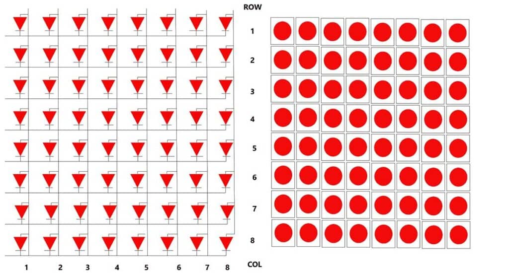
As you can see, all anodes of the same row are connected to one pin, and all cathodes of the same column are connected to another pin. It has 8-row pins and 8-column pins.
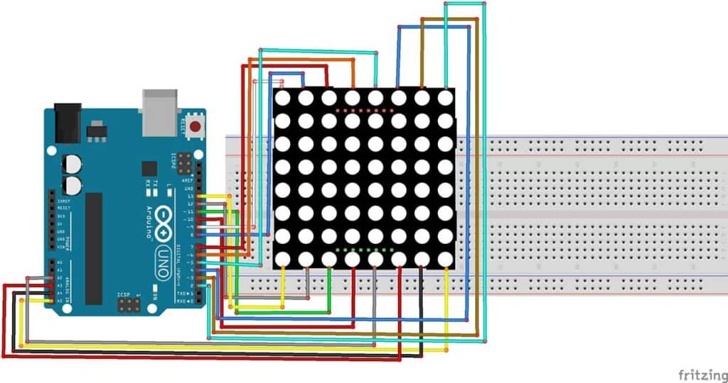
Wiring Dot-matrix Display with Arduino UNO
Dot-matrix Display Pinout is given in the table below:
| Pin no. | Pin Name | Arduino Connection |
| 1 | ROW_1 | Pin 2 |
| 2 | ROW_2 | Pin 3 |
| 3 | ROW_3 | Pin 4 |
| 4 | ROW_4 | Pin 5 |
| 5 | ROW_5 | Pin 6 |
| 6 | ROW_6 | Pin 7 |
| 7 | ROW_7 | Pin 8 |
| 8 | ROW_8 | PIn 9 |
| 9 | COL_1 | Pin 10 |
| 10 | COL_2 | Pin 11 |
| 11 | COL_3 | Pin 12 |
| 12 | COL_4 | Pin 13 |
| 13 | COL_5 | Pin A1 |
| 14 | COL_6 | Pin A2 |
| 15 | COL_7 | Pin A3 |
| 16 | COL_8 | Pin A4 |
For more details, see our full guide on using a Dot-matrix Display with Arduino.
How many displays can an Arduino run?
Arduino can run a maximum of two displays simultaneously, but it depends on the type of display and what else you have connected to your output pins. You can run more displays than this if you add additional hardware.
Comparison of Arduino Compatible Displays
In this section, I will tell you how to select the display for your electronics project with an Arduino Board.
If you are using MCU with more GPIOs, have enough physical space, and want to display different characters for any data, information, and graphics, then you can go for Liquid Crystal Display (LCD) or Graphical Liquid Crystal Display (GLCD).
They are primarily used in embedded systems.
If you only want to display some numbers and alphabets, then Seven-Segment Display or Dot-matrix Display is best suitable for such a project.
It is mainly used in digital clocks, calculators, counters, electronic meters, etc.
If you have a very compact project and you want to use fewer GPIOs and color graphics, then OLED is the best option. It is widely used in smartwatches, pulse oximeters, etc.
If the project needs high-quality graphics with GUI and also if you want touch operation, then TFT LCD or TFT LCD touchscreen is the most suitable.
It is widely used in mobile devices, cameras, aircraft devices, etc.
Conclusion
After this tutorial, you can easily choose the right displays corresponding to your project.
You have learned how to connect your displays with the Arduino Board, and you can follow the links I shared to more in-depth tutorials that we have on this site for each different display type.
I hope you found this tutorial informative. If you did, please share it with a friend who likes electronics and making things!
I would love to know what project you plan on building or have already made with the Arduino.
If you have any questions or suggestions or think things are missing in this tutorial, please leave a comment below.

Hiren is a professional Embedded Engineer with a Master’s Degree
in Electronics and Communication Engineering. He is proficient in C and
C++ and enjoys building DIY projects on Arduino, ESP32, PIC32, STM32 & Raspberry PI boards.