In this article, you will learn how to use a 2-axis potentiometer joystick with Arduino.
The joystick is a very critical input component in HMI controller pads.
The joystick provides you with very precise control over the navigation. It might be a game or a menu control.
Joysticks find their applications in robotic arm control, wheelchairs, lawn mowers, remote car control, crane control, and many more.
I will take you through the basic building blocks of a joystick.
Once we understand the working principle, we will build a simple Arduino and joystick project where you can control the mouse on a computer screen!
Let’s get started!
Components Needed To Build Arduino And Arduino Joystick Project
Hardware Components
- Dupont wire
- Arduino USB cable (for powering Arduino and programming) x 1
- Breadboard x 1 (optional)
Software
Makerguides.com is a participant in the Amazon Services LLC Associates Program, an affiliate advertising program designed to provide a means for sites to earn advertising fees by advertising and linking to products on Amazon.com.
How does a Joystick work?
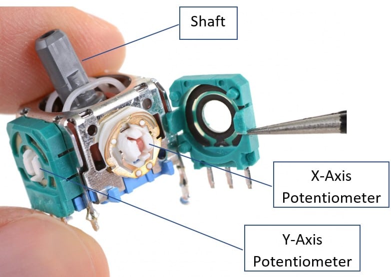
The joystick consists of two potentiometers. One potentiometer for the X-axis movement and the other for the Y-axis movement.
The potentiometers always rest in the central position. If the potentiometer is powered by 5 V, the analog value measured at the center of the potentiometer will be 2.5 V.
In the below image, you can see the internal parts of the joystick.
You need two analog input pins on the Arduino UNO to read the joystick data. I have created simple graphics which show the expected analog values you read from the two potentiometers.
Both potentiometers idle in the center position automatically. It means the value read will be half of the maximum resolution of the ADC.
For Example, if the ADC bit is 10 bit, then the default value read by the analog inputs will be 512.
The ADC counts will be 512 for the potentiometer in the resting position.
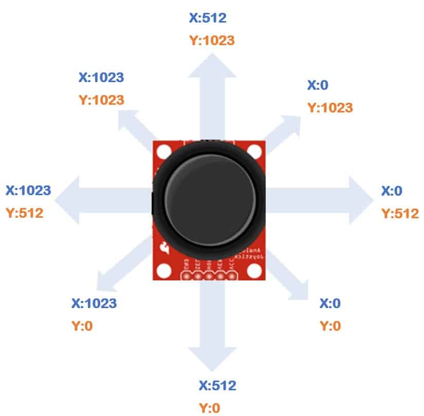
In the above image, you can see the ADC counts you can expect at different shaft positions.
When you move the shaft forward, the X-axis potentiometer stays idle, but the Y-axis potentiometer moves all the way forward.
Hence the ADC counts for the X-axis and Y-axis are 512 and 1024, respectively.
The joysticks will also have a momentary switch present which you can use for specific applications.
Hence, a single joystick is sometimes all you need to complete various tasks.
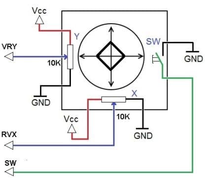
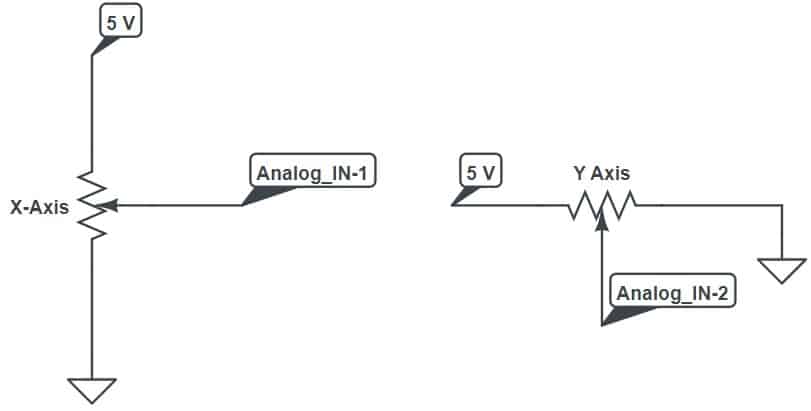
The above image shows an electrical representation of a two-axis joystick. You can also see the switch option.
Notice that there is a ten kOhms potentiometer inside the joystick. Not all the joysticks will have ten kOhms.
It doesn’t matter since what we read as the analog voltage is only the relative difference in the voltage.
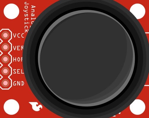
Let us see the pinouts of a commonly available joystick.
| Sl. No | Pin label | Pin Function |
| 1 | GND | Ground Connection |
| 2 | 5V | Supply pin for the joystick. The 5 V provides biasing voltage for the potentiometers |
| 3 | VRx | Analog voltage output for the X-axis potentiometer |
| 4 | VRy | Analog voltage output for the Y-axis potentiometer |
| 5 | SW | Switch output. The pin goes low when the switch is pressed |
You need two analog input pins and a digital input pin on the Arduino to complete the connection.
You can use any of the two Analog inputs on the Arduino UNO.
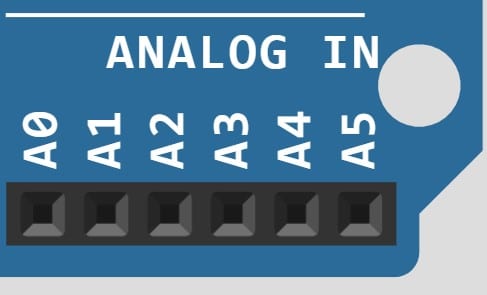
Arduino UNO has six analog input pins labeled A0, A1, A2, A3, A4, and A5.
Note: Though I said that the ADC would read 512 counts when the potentiometer is idle, it will not be precisely halfway. You can see an offset of 5 or 10 counts. Hence, you can calibrate all three positions: extreme left, extreme right, and idle.
While calibrating the joystick, take enough readings and average them to find the offset.
I recommend taking at least 100 counts. This helps to remove noise and choose a better offset correction value.
Let’s see the calibration for the X-axis potentiometer.
- Keep the joystick idle (center Position)
- Read the ADC analog value.
- Make sure that the reading is between 500 to 520. This is to ensure that the position of the shaft is in the expected position/state
- Keep adding the readings to a variable.
- Repeat steps from 2 to 4 for 100 times
- Compute the average (Total sum / 100)
- Store the new “mid” value.
Similarly, you can calibrate the X-axis potentiometer for end positions. Follow the same steps for the Y-Axis potentiometer as well.
Step-By-Step Instructions To Connect A 2-Axis Joystick To Arduino
In this section, we will go through the connections needed between Arduino UNO and the Joystick module.
Let’s get started.
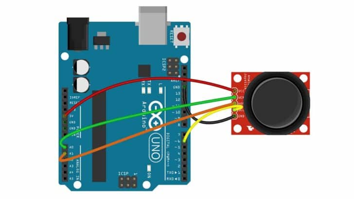
How To Connect Joystick Module With Arduino UNO
The connections are simple and take less time to complete.
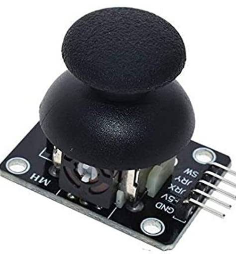
Step 1: Start with the Arduino Joystick module
You can see that there are five pins on the left side of the module: GND, SEL, HOR, VER, and VCC.
Step 2: Make the Ground connection
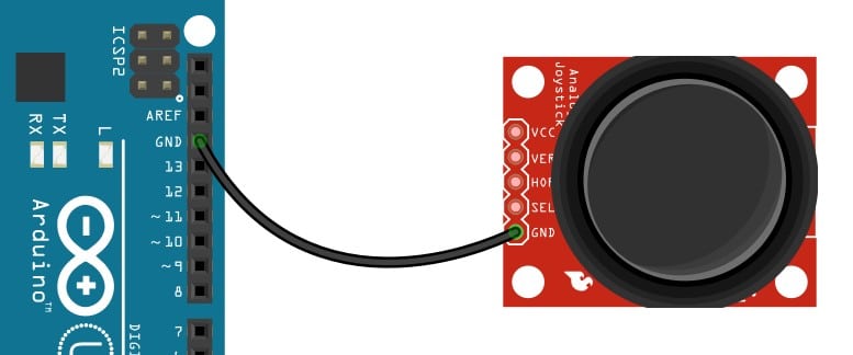
Connect one of the GND pins of the Arduino to the “GND” labeled pin on the joystick module.
I always insist on starting the connections by connecting GND connections first.
Step 3: Connect the Analog Joystick’s SEL Pin
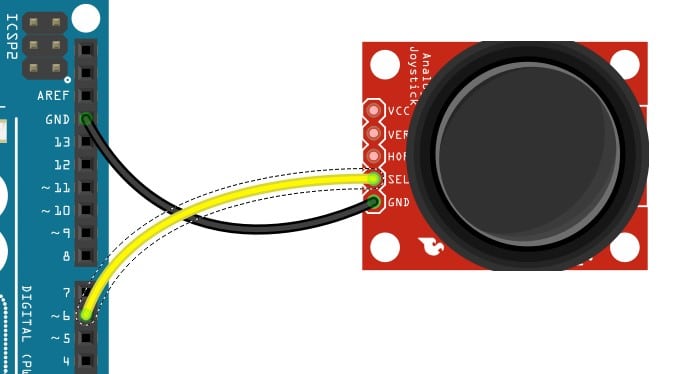
The SEL pin may be labeled as SW as well. This is the momentary switch present in the module.
Remember to enable internal pullup on this pin. Connect the SEL pin to Pin 6 of the Arduino UNO.
Step 4: Connect the Analog Pin A1
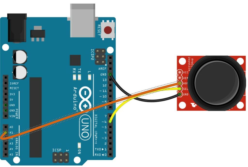
Connect the Arduino UNO’s analog input pin A1 to the “HOR” labeled pin of the module. HOR label is also known as X-axis / VRx etc.
Step 5: Connect the Analog Pin A0
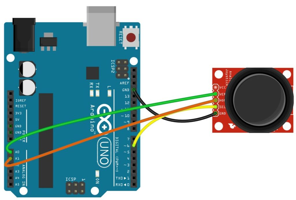
Connect the Arduino UNO’s analog input pin A0 to the “VER” labeled pin of the module. HOR label is also known as Y-axis / VRy etc.
Step 6: Connect Power Pins
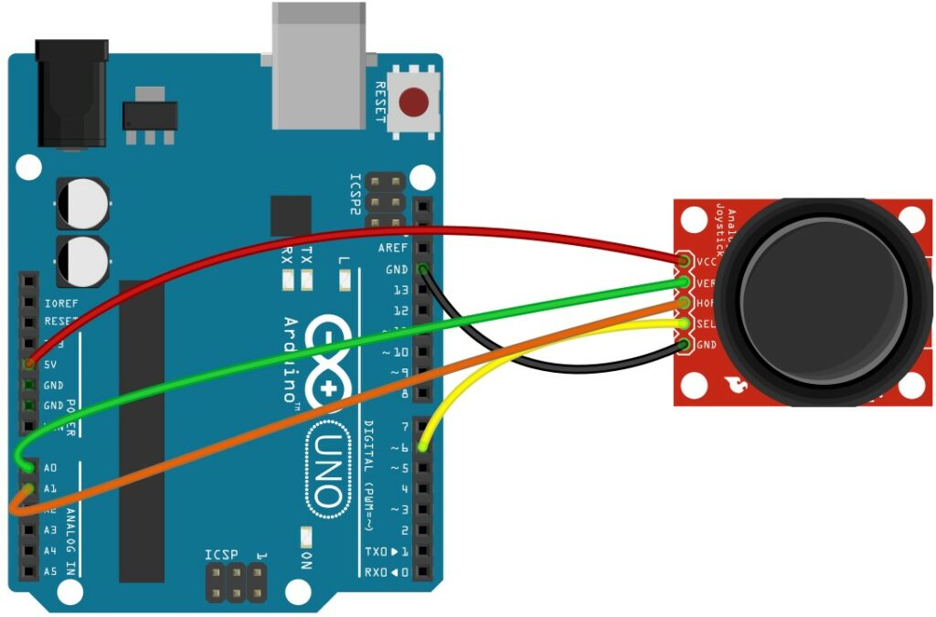
Connect the Sensor pin labeled VCC to the Arduino 5 V pin.
Congrats! You have now completed the hardware connections. In the next section, you will see an example code.
Simple Arduino Code For Controlling PC Mouse Cursor Using Joystick
This Arduino sketch will control the mouse cursor on the screen. This project is very exciting to me, and I believe you will enjoy this too.
#include "Mouse.h"

// set pin numbers for switch, joystick axes, and LED:
const int switchPin = 2;      // switch to turn on and off mouse control
const int mouseButton = 3;    // input pin for the mouse pushButton
const int xAxis = A0;         // joystick X axis
const int yAxis = A1;         // joystick Y axis
const int ledPin = 5;         // Mouse control LED

// parameters for reading the joystick:
int range = 12;               // output range of X or Y movement
int responseDelay = 5;        // response delay of the mouse, in ms
int threshold = range / 4;    // resting threshold
int center = range / 2;       // resting position value

bool mouseIsActive = false;    // whether or not to control the mouse
int lastSwitchState = LOW;        // previous switch state

void setup() {
  pinMode(switchPin, INPUT);       // the switch pin
  pinMode(ledPin, OUTPUT);         // the LED pin
  // take control of the mouse:
  Mouse.begin();
}

void loop() {
  // read the switch:
  int switchState = digitalRead(switchPin);
  // if it's changed and it's high, toggle the mouse state:
  if (switchState != lastSwitchState) {
    if (switchState == HIGH) {
      mouseIsActive = !mouseIsActive;
      // turn on LED to indicate mouse state:
      digitalWrite(ledPin, mouseIsActive);
    }
  }
  // save switch state for next comparison:
  lastSwitchState = switchState;

  // read and scale the two axes:
  int xReading = readAxis(A0);
  int yReading = readAxis(A1);

  // if the mouse control state is active, move the mouse:
  if (mouseIsActive) {
    Mouse.move(xReading, yReading, 0);
  }

  // read the mouse button and click or not click:
  // if the mouse button is pressed:
  if (digitalRead(mouseButton) == HIGH) {
    // if the mouse is not pressed, press it:
    if (!Mouse.isPressed(MOUSE_LEFT)) {
      Mouse.press(MOUSE_LEFT);
    }
  }
  // else the mouse button is not pressed:
  else {
    // if the mouse is pressed, release it:
    if (Mouse.isPressed(MOUSE_LEFT)) {
      Mouse.release(MOUSE_LEFT);
    }
  }

  delay(responseDelay);
}

/*
  reads an axis (0 or 1 for x or y) and scales the analog input range to a range
  from 0 to <range>
*/

int readAxis(int thisAxis) {
  // read the analog input:
  int reading = analogRead(thisAxis);

  // map the reading from the analog input range to the output range:
  reading = map(reading, 0, 1023, 0, range);

  // if the output reading is outside from the rest position threshold, use it:
  int distance = reading - center;

  if (abs(distance) < threshold) {
    distance = 0;
  }

  // return the distance for this axis:
  return distance;
}
FAQs About The Joystick And The Arduino Projects
I have answered the most frequently asked questions about the Joystick and the Arduino projects.
You may find most of the answers here.
If you have any other questions, please post them in the comments section.
1) How does a Joystick work?
The basic building block of a joystick includes potentiometers with a spring. The springs will pull the potentiometers to the default position when the user is not operating them.
When you use the joystick, you turn the potentiometer. The standard joystick you find in HMI controllers, handheld gaming controllers, etc., will have two potentiometers for each axis.
The Arduino monitors the analog values from both potentiometers. The two analog values are then translated into the correct position.
2) How do you reduce the jitter in the joystick reading?
The joystick will give you two analog readings. You can use the built-in ADC to read the analog values. To reduce the jitter in the readings, follow the suggestions below.
- Stable Power Supply: Ensure the 5 V supply is stable. Provide enough capacitors between 5 V and ground. Also, add small-value capacitors (100pF, for example) between the ground and the potentiometer wiper pin. This filters the jitter on the line significantly
- Stable Analog voltage reference: The ADC essentially compares the input analog voltage with the ADC reference voltage. By default, Arduino uses the 5 V supply pin itself as the analog voltage reference.
When you are driving a motor, switching a high current load, an LED strip, for example, the 5 V will not be stable. The instability of 5 V (also the ADC reference) creates a jitter in the analog reading.
The idea is to use a stable dedicated reference voltage for the ADC VREF input pin. You can find voltage reference ICs (TL431, for example) built for this purpose. Please refer to the link to understand more about choosing the ADC reference.
- Poor quality Joystick: It is also possible that the joystick is damaged or the assembly has an issue. The tiny vibrations can create mechanical jitter, which translates to jitter in the ADC reading.
- Implement ADC averaging: Since the joystick movement is not a high-speed operation, you can take multiple samples and average them.
I am confident that your readings will be stable if you have taken all the precautions above.
3) Can I control the computer mouse using an Arduino Joystick?
Yes. You can control the mouse cursor on the screen using Arduino UNO. You can use the mouse library to control the cursor.
Please refer to the sections above for details on the connection diagram and the Arduino code.
Conclusion
In this article, We saw the working principle of the 2-Axis joystick. Later, we went through some critical parameters we should consider in order to reliably read and process the analog outputs from the joystick.
I am hoping that you were able to build the project and test it easily. If you have any suggestions to improve the article, please share them in the comments section.
It will help me to improve the article so that all our readers will be benefited.
I will be glad to know about the projects you built using a joystick.
Please post a link to your projects in the comments section.
If you find some useful projects and would like to learn about them, let me know!
I will be excited to write a detailed guide on them.
Don’t forget to share the article with your friends and Arduino enthusiasts.
Benne is professional Systems Engineer with a deep expertise in Arduino and a passion for DIY projects.