In this guide, I will teach you about the I2C IO expander – MCP23017, which enables you to control up to 128 GPIO pins using only two lines on an Arduino.
If you sometimes feel the number of GPIOs on the Arduino is too limited then this is the tutorial for you. For example, if you want to control 20 LEDs or a 4×7 segment display, you can use the IO expander ICs to increase the number of inputs, outputs, or both.
In this tutorial, I will take you through the basic working principle of the IO expander. I will provide a step-by-step guide to connect an MCP23017 module to an Arduino UNO. I will also show you a complete working Arduino code example.
By the end of the tutorial, you will find the applications and answers to the most frequently asked questions about the IO expander.
Let’s get started!
Components Needed To Build Arduino MCP23017 Project Project
Hardware Components
- Dupont wire x 1 set
- Arduino USB cable (for powering Arduino and programming) x 1
Software
Makerguides.com is a participant in the Amazon Services LLC Associates Program, an affiliate advertising program designed to provide a means for sites to earn advertising fees by advertising and linking to products on Amazon.com.
Basics of The MCP23017 IO Expander IC
In this section, we will understand more about the MCP23017 IC. I will cover details about the electrical parameters, pin functions, and more. By the end of this section, you will know how to add MCP23017 IO expanders to your applications to increase the number of GPIOs.
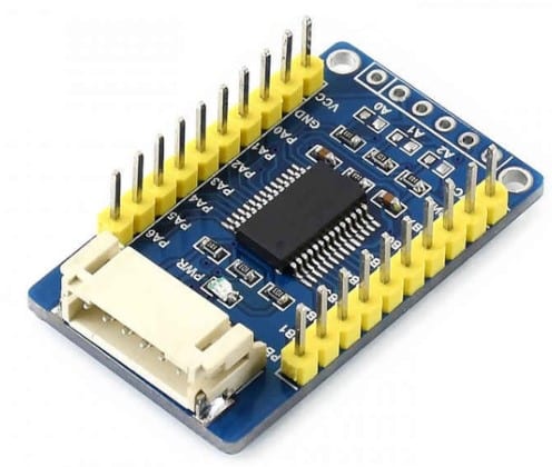
Basic features of MCP23017 module
Below you can see the block diagram of the MCP23017 I/O Expander IC. It consists of an I2C interface for communication with Arduino, and also an address line selection for the IC, SERDES (serialise and de-serialise), GPIO ports, and interrupt pins.
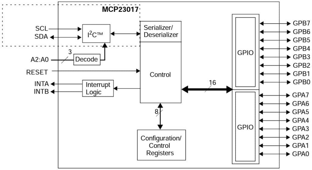
MCP23017 IC is an I2C-based IO expander. It has the following features.
- Provides 16 GPIOs: All 16 can independently act like input or output pins.
- Supports I2C interface with all modes ( 100 kHz, 400 kHz, as well, and 1 MHz)
- You can configure the I2C address. You have three pins which you can either connect to high or low. In total, you can have eight addresses.
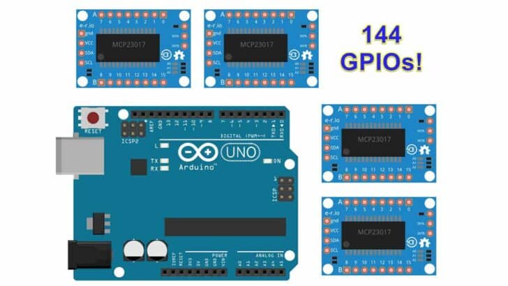
- With 8 I2C addresses and 16 GPIO pins per expander module you could control up to 8 * 16 = 128! GPIO pins.
- Supports interrupt features – You can generate an interrupt when a pin changes.
- Wide operating voltage range – 1.8 V to 5.5 V
- Low standby current – Hence a good choice for battery-powered devices.
Pin-out of MCP23017 IO Expander
Here is the pin-out diagram of the MCP23017. The IC has 28 pins. The function of the individual pins is explained in the table below.
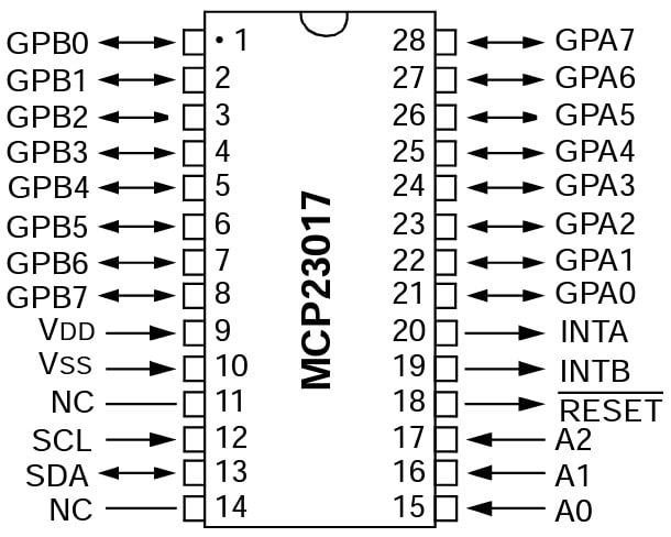
| Pin label | Pin Description |
| GPB0-GPB7 | Bidirectional Input Output pin. Can be enabled for interrupt-on-change and/or internal weak pull-up resistor |
| GPA0-GPA7 | Bidirectional Input Output pin. Can be enabled for interrupt-on-change and/or internal weak pull-up resistor |
| VDD | Power |
| VSS | Ground |
| NC | No connection. Leave the pin unconnected |
| SCL | Serial clock line (I2C) |
| SDA | Serial data line (I2C) |
| A0 | Hardware address pin A0 – Must be externally biased |
| A1 | Hardware address pin A1 – Must be externally biased |
| A2 | Hardware address pin A2 – Must be externally biased |
| RESET# | Active low reset pin |
| INTB | Interrupt output for Port B. Can be configured as active-high, active-low or open-drain |
| INTA | Interrupt output for Port A. Can be configured as active-high, active-low or open-drain |
The IC has three address configuration pins. You can connect up to 8 IO modules onto the I2C line of the Arduino UNO. Just make sure each module has its unique address configured.
The below table has the information about all the 8 I2C addresses you can create using 3 address lines.
| Address bit settings | I2C Address |
| 000 | 0100000 |
| 001 | 0100001 |
| 010 | 0100010 |
| 011 | 0100011 |
| 100 | 0100100 |
| 101 | 0100101 |
| 110 | 0100110 |
| 111 | 0100111 |
Electrical Specifications Of MCP23017
The MCP23017 IC can be powered from 5 V or 3.3 V. Let us see a few critical electrical parameters of the IC, which are essential to ensure you can build the project.
| Characteristic | Range | Remarks |
| Supply voltage | 1.8 V to 5.5 V | Connect 3.3 V for Arduino devices powered by 3.3 V. Connect this pin to 5 V if you need to connect Arduino UNO. |
| Supply Current | 1 mA | 1 mA is the quiescent current (when no GPIOs are connected) |
| Standby current | 1 uA | Good choice for battery powered devices |
| Logic voltage (low) | 0.2 x VDD | If the supply is 5 V the logic low voltage level will be 1 V. Anything lower than 1 V will always be detected as logic 0. |
| Logic voltage (High) | 0.8 x VDD | If the supply is 5 V the logic low voltage level will be 1 V. Anything lower than 1 V will always be detected as logic 0. |
| Output Low voltage | 0.8 V | Maximum |
| Output high voltage | VDD – 0.7 V | Minimum |
Applications Of The IO Extender IC – MCP23017
In the image below you can find the application of an IO expander.
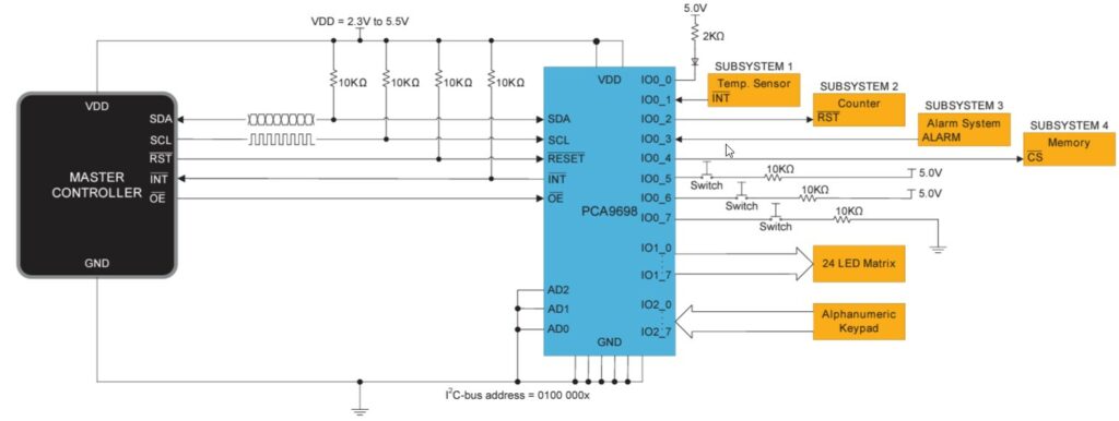
The I2C interface allows you to control the IO expander. The IO expander is a popular choice for computing, consumer electronics, communication, industrial and automation systems.
Here some examples of situations where you may utilise this module:
- LED Matrix application – LED matrices typically need 8 to 12 IO lines. Connecting the LED matrix module directly to the MCU will use up a lot of MCU pins. An IO Expanders, in this case, is the best solution. For more details read our guide on Interfacing an LED Dot Matrix display with Arduino
- Keypads – You can save many MCU pins when working with matric switches or keypads. IO expanders are fast in responding. You can easily use IO expanders to interface alphanumeric keypads to an MCU using only two I2C lines. Have a look at our tutorial on How to use a Keypad with Arduino, if you want to do this.
- Collective interrupts from multiple subsystems – You can use MCP23017 to interrupt the main MCU. Here, the MCP23017 will collect all the interrupts from the other subsystems and interrupt the MCU. MCU can collectively read the interrupts and take action later.
- Interfacing to relay boards – You can use IO expanders to connect relay boards to the Arduino. Relay boards usually contain 4 to 16 relays on board. Each relay needs a dedicated GPIO pin to control them. IO expanders come in handy in these situations too. For more information, see our post Using a Relay With Arduino.
Step-By-Step Instructions To Connect The MCP23017 IO Expander With Arduino UNO
In this section, we will build a project using Arduino UNO and the IO Expander MCP23017.
First I will cover the hardware connections, and then share some example code for a couple of simple projects.
How To Connect The MCP23017 IO Expander To The Arduino UNO?
Below is the step-by-step connection guide to complete the Arduino and the MCP23017 IO expander module.
Step 1: Start with the GND connections
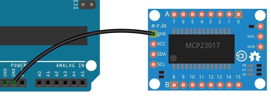
You can choose any GND pins on the Arduino to complete the GND connections. It is a good practice to connect the GND pins first.
Connect the GND pin of the MCP23017 board to the GND pin of the Arduino UNO.
Step 2: Connect the SDA pin
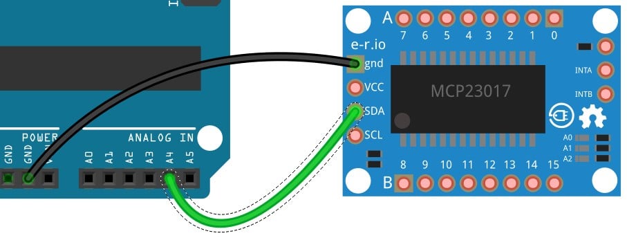
Connect the I2C data pin (SDA) of the MCP23017 module to the Arduino UNO Pin A4. The I2C data line is Pin A4 on the Arduino UNO.
Step 3: Connect the SCL pin
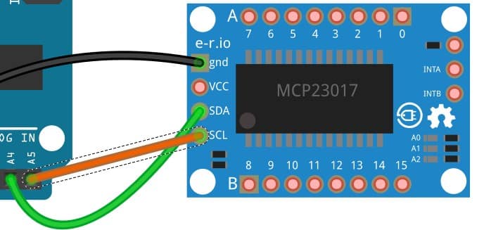
Connect the I2C clock pin (SCL) of the MCP23017 module to the Arduino UNO Pin A5. The I2C clock line is Pin A5 on the Arduino UNO.
Step 4: Complete the power connection
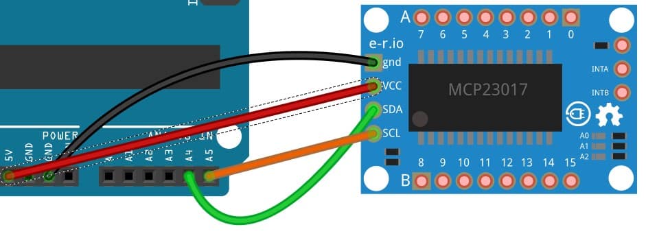
Connect 5 V on the Arduino UNO to the VCC pin of the MCP23017 module.
Step 5: Complete connection diagram
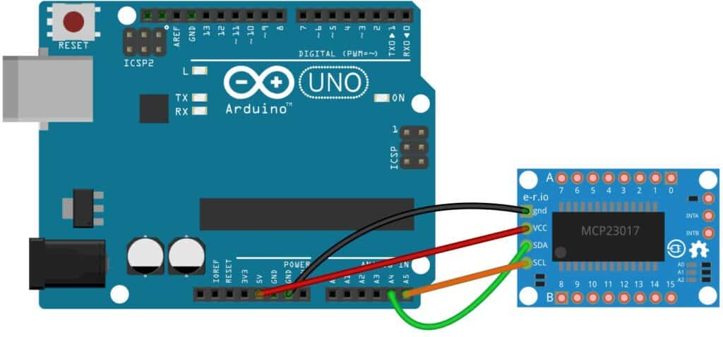
Congratulations, with these connections, you can communicate with the IO expander and test the connections.
You can use the below sketch to control the IO expander using Arduino. In this example, you will turn on and turn off an LED connected to the IO expander using a switch also connected to the Arduino board. You can find the connection diagram below:
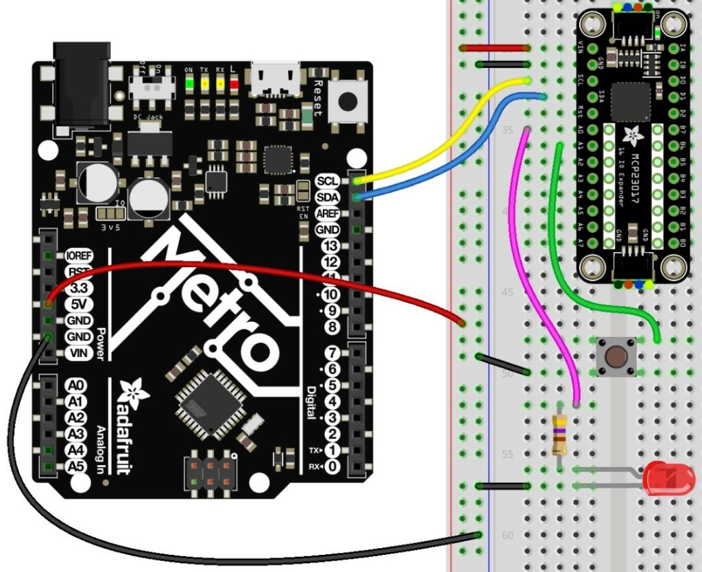
LED connections
- Connect a 470 ohm resistor to the Anode pin of the LED.
- Connect the cathode pin of the LED to the GND pin of the UNO.
- Connect the other end of the 470 ohm resistor to Pin A0 of the IO Expander.
Button connections
- Connect the button leg to IO expander pin A1
- Connect the opposite button leg to GND pin of the board
Arduino Code
Code to control an LED with a Switch
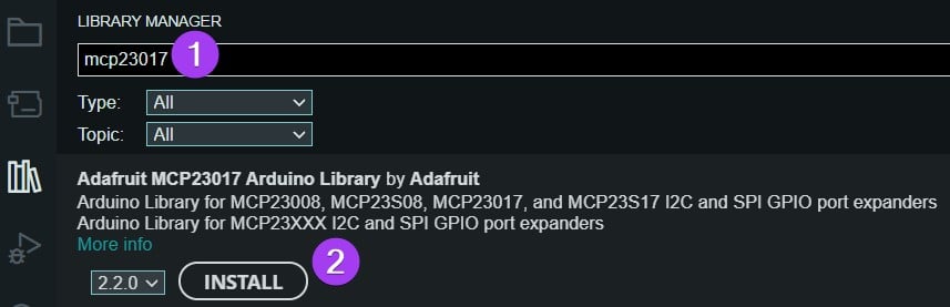
Install the Adafruit MCP23017 library.
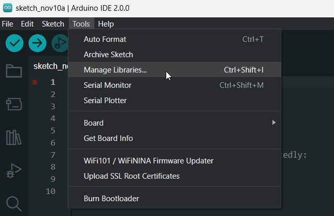
Go to Tools and select manage libraries.
- Search MCP23017 in the search bar.
- Click Install
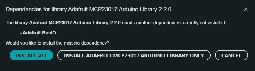
When asked, select install all the dependent libraries
The complete Code
// Controls an LED via an attached button.

// ok to include only the one needed
// both included here to make things simple for example
#include <"Adafruit_MCP23X08.h"
#include "Adafruit_MCP23X17.h"

#define LED_PIN 0     // MCP23XXX pin LED is attached to
#define BUTTON_PIN 1  // MCP23XXX pin button is attached to

// only used for SPI
#define CS_PIN 6

// uncomment appropriate line
Adafruit_MCP23X08 mcp;
//Adafruit_MCP23X17 mcp;

void setup() {
  Serial.begin(9600);
  //while (!Serial);
  Serial.println("MCP23xxx Combo Test!");

  // uncomment appropriate mcp.begin
  if (!mcp.begin_I2C()) {
  //if (!mcp.begin_SPI(CS_PIN)) {
    Serial.println("Error.");
    while (1);
  }

  // configure LED pin for output
  mcp.pinMode(LED_PIN, OUTPUT);

  // configure button pin for input with pull up
  mcp.pinMode(BUTTON_PIN, INPUT_PULLUP);

  Serial.println("Looping...");
}

void loop() {
  mcp.digitalWrite(LED_PIN, !mcp.digitalRead(BUTTON_PIN));
}
Code to blink an LED connected to Pin A0 of the IO Expander
// Blinks an LED attached to a MCP23XXX pin.

// ok to include only the one needed
// both included here to make things simple for example
#include "Adafruit_MCP23X08.h"
#include "Adafruit_MCP23X17.h"

#define LED_PIN 0     // MCP23XXX pin LED is attached to

// only used for SPI
#define CS_PIN 6

// uncomment appropriate line
Adafruit_MCP23X08 mcp;
//Adafruit_MCP23X17 mcp;

void setup() {
  Serial.begin(9600);
  //while (!Serial);
  Serial.println("MCP23xxx Blink Test!");

  // uncomment appropriate mcp.begin
  if (!mcp.begin_I2C()) {
  //if (!mcp.begin_SPI(CS_PIN)) {
    Serial.println("Error.");
    while (1);
  }

  // configure pin for output
  mcp.pinMode(LED_PIN, OUTPUT);

  Serial.println("Looping...");
}

void loop() {
  mcp.digitalWrite(LED_PIN, HIGH);
  delay(500);
  mcp.digitalWrite(LED_PIN, LOW);
  delay(500);
}
FAQs About The IO Expander MCP23017 And Arduino Projects
I have included a list of the most frequently asked questions about projects built using Arduino and the IO expander IC MCP23017.
How do I connect my Arduino to the MCP23017?
You can connect the MCP23017 to the Arduino using I2C lines. You can use the SDA and SCL lines of the Arduino UNO. The SDA pin is on the A5 pin of the Arduino. The SCL pin is on the A4 pin of the Arduino.
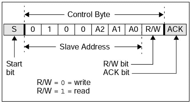
How do I address the MCP23017?
MCP23017 supports I2C communication. The I2C address of the MCP23017 IC depends on the termination of the three pins, A0, A1, and A2.
The advantage of having configurable address lines is you can address up to eight MCP23017 IO Expander.
What is the MCP23017?
MCP23017 is an IO expander. It supports an I2C interface. MCP23017 has 16 GPIOs. You can configure each GPIO as either an input or an output.
You can use the MCP23017 IO expander to connect keypads, LED boards and other interfaces which demand more pins easily to the Arduino.
How much current can the MCP23017 supply?
The MCP23017 can support up to 8 mA to drive the load. Here is a screenshot from the datasheet.
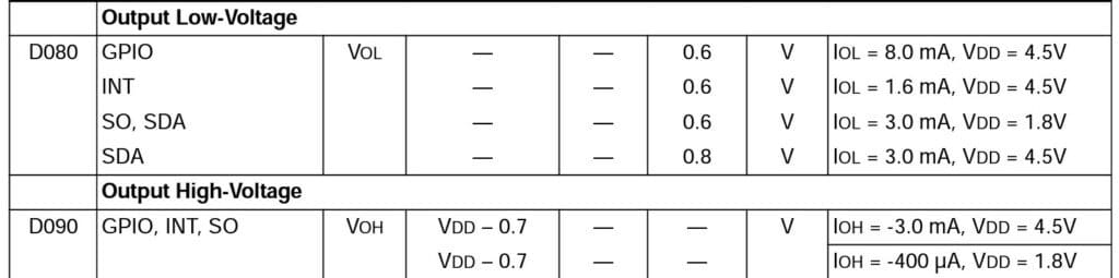
The MCP23017 can sink up to 8 mA at 5 V. The current sourcing ability is 3 mA at 5 V.
This is sufficient to drive individual LEDs for most kinds of displays.
Conclusion
MCP23017 is a versatile circuit for expanding the number of GPIOs. In this article, we covered the basics of the IC and went through the pin details.
We also built a simple project to test the connections and included some example code that you can use.
If you have any questions regarding the IO expander project, I will answer your queries in the comments section.

I am Puneeth. I love tinkering with open-source projects, Arduino, ESP32, Pi and more. I have worked with many different Arduino boards and currently I am exploring, Arduino powered LoRa, Power line communication and IoT.
Mat Smith
Tuesday 31st of October 2023
Great article, however the title says you can use the chip to connect up to 144 inputs to an Arduino. With 3-bit addressing giving 8 possible addresses, and 16 IOs per chip, that would be 8x16 = 128, not 144?
Stefan Maetschke
Wednesday 1st of November 2023
Good catch! Thanks for pointing it out. Yes, it is 128 and not 144. I corrected the wrong number.