Input devices let the Arduino and other microprocessors interact with the world. Without it, an Arduino would simply run its program with no way to respond to the external environment or user commands.
Here we provide an overview of all the different types of input devices that can be connected to an Arduino or similar microprocessors. We discuss their functional principles and what to watch out for.
The terms Inputs and Sensors somewhat overlap. Here we will use Inputs to refer to inputs originating from human or machine interaction with the system. For instance, via buttons, switches, touch-displays or potentiometers. Sensors, on the other hand, are used to detect or measure environmental parameters, such as temperature, light, distance or magnetic fields.
Makerguides.com is a participant in the Amazon Services LLC Associates Program, an affiliate advertising program designed to provide a means for sites to earn advertising fees by advertising and linking to products on Amazon.com. As an Amazon Associate we earn from qualifying purchases.
Input devices
In the following we have a look at all the different types on inputs, initiated by human interaction, an Arduino or similar microprocessor can receive. Most frequently, these will be buttons and switches but there are others.
Buttons
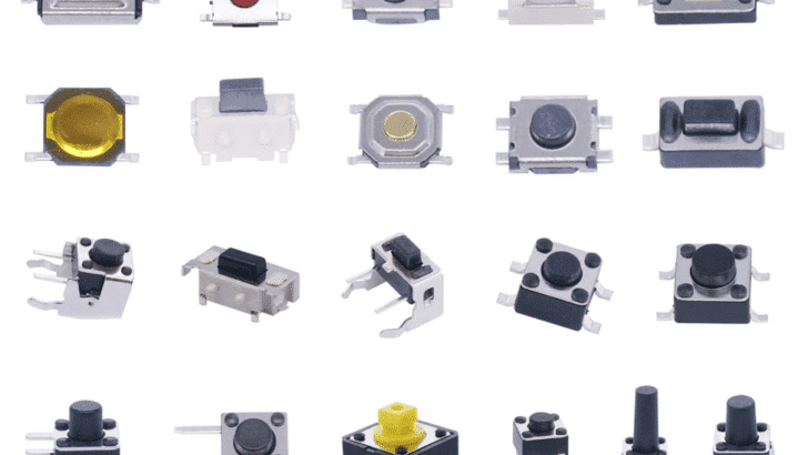
Buttons come in all types of shapes, sizes and colors. Below is the picture of a typical push button that closes the electrical connection between its two poles when pressed and is open otherwise.
Momentary Push Button Switch, 1A 250VAC SPST Mini Pushbutton Switches Normally Open (NO).
When selecting a button as an input device, there are several aspects to consider. Firstly, is obviously the size and related to that is the Voltage and Current rating of the button. For controlling the digital input to an Arduino board, tiny buttons that can switch up to 12 Volt and 0.1 Ampere are sufficient. They are very cheap and it is useful to have a selection of various types for different applications. I like the set below.
TWTADE 260pcs Micro Momentary Tact Switch Tactile Push Button Switch 26 Values 4 pin/3 pin/2 pin Assortment Kit QC-26V.
| Operation Mode | ON-OFF |
| Current Rating | 0.1 Amps |
| Tensión de funcionamiento | 12 Volts |
If you want to switch typical loads, like small electro-motors or the battery power for your Arduino a switch rated for 12V and 1 to 3A will be okay. Note that switching appliance connected to mains (110V – 220V) is dangerous! You must select a switch rated for 110V or 220V (depending on your country) and 5A or higher (depending on the load).
Normally open or close
Most buttons that are normally open when not pressed (marked as NO). Meaning electrical current does not flow when the button is not pressed. This is the type we commonly use. But there are also buttons that are normally closed (NC), when not pressed.
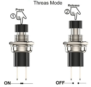
Momentary vs maintained buttons
Also most buttons are momentary buttons, meaning they are snapping back to their default position, when released. A maintained button, on the other hand, remains in its position when pressed and needs to be pressed again to return to normal. We use maintained buttons mostly to switch electrical power on or off. Note that some buttons even have three states such as ON – NONE – OFF or alike.
Number of poles
Finally, most button have two contacts (aka two Poles) that are used to make the electrical connection. However, there are some buttons with more poles and different switching configurations. More about that in the Switches section below.
Some buttons are even illuminated and have additional contacts to provide power for the integrated light. Don’t mix those ones up!
Key considerations
Rating
The most important factor to consider when selecting a button is the correct rating. The button must be able to handle the voltage and current of the circuit it controls. Also make sure to use the correct voltage and polarity for illuminated buttons.
Debouncing
The contacts within the button are made of metal, which has a certain elasticity. This causes the contacts bounce for a short while (a few milliseconds) when the button is pressed, instead of making steady contact right away. We don’t get a transition from open to closed in the shape of nice stepping pattern, but a jittery transition. See the bouncing effect below:

When reading the state of button with a microcontroller this can result in reading multiple button presses, instead of a single one. Typically you will need to either write specific code for debouncing a button or add a debouncing circuit, using a resistor and capacitor. We have an example on how to connect a push button to an Arduino.
Pull-up resistors
When a button is open (not pressed), the pin it is connected to can float between high and low states because it’s not connected to a definite voltage. This “floating” state can lead to unpredictable readings, since the pin essentially works as an antenna that picks up electro-magnetic waves from the environment.
We can use pull-up resistors to connect the pin to the voltage supply (usually 5V or 3.3V). This ensures that it is in a defined state (HIGH), when the button is not pressed. Many Arduino boards have built-in pull-up resistors that can be activated in software using pinMode(pin, INPUT_PULLUP).
However, it is always a good idea to be on the save side and add a pull-up resistor. This way you can use your circuit with different boards or on different pins (which may not have internal pull-up resistors).
Current limiting resistors
Although not always necessary when using pull-up or pull-down resistors, sometimes it’s a good idea to include a current limiting resistor in series with a button, especially if connecting directly to power and ground. This helps prevent excessive current flow when the button is pressed.
Logic levels
Finally, we need to watch out for the different logic levels of the Arduino (which is usually 5V) and other common MCUs, such as the ESP32, which operates with 3.3V. For instance, connecting 5V to 3.3V input on an ESP32 can damage the chip. Similarly, using more than 5V as an Arduino input can cause damage. The aforementioned current limiting resistors can offer some protection.
Switches
Similar to buttons, switches come in all kinds of shapes and sizes. Below a typical, small switch that can be used to switch logical inputs or small loads:
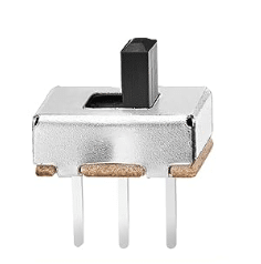
Chanzon SPDT Mini Micro Slide Switch 2 Positions.
Note: Pick the ones with a pin pitch of 2.54 mm (0.1″) to be breadboard compatible.
Momentary vs maintained/latching switches
Switches are essentially the same input devices as buttons – and sometimes buttons are called switches. But while the most commonly used buttons are momentary buttons, the switches are typically of the maintained or latching type.
However, you will also find momentary switches. A momentary type, I frequently use, is this micro-switch that takes very little force to actuate and is great to detect collisions (for robots) or the opening/closing of doors:
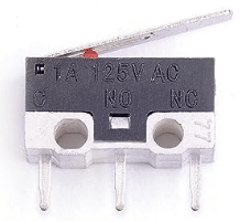
Cylewet 25Pcs AC 1A 125V 3Pin SPDT Limit Micro Switch Long Hinge Lever.
If you look closely, you see the markings C (Contact), NO (Normal Open) and NC (Normal Closed) for the pins. This is a SPST (Single Pole, Single Throw) type of switch and we talk more about that in the next section.
Contact terminology
Another difference between switches and buttons is, that switches tend to come with many more variations in Pole and Throw configuration.
Whereby Poles refers to the number of separate circuits the switch can control. It’s essentially the number of independent inputs a switch has. Throws, on the other hand, refers to the number of paths available for each pole. It describes how many output connections each pole can be connected to or “thrown” to.

The most common configuration, a simple switch, has SPST (Single Pole, Single Throw) configuration.
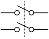
A switch with two Poles and one Throw is called a DPST (Dual Pole, Single Throw) switch.
A DPST switch I have been using in many of my projects is the following one. While it is a small switch it can switch considerable load and is definitely sufficient to switch battery power, for instance. Note that this one cannot be inserted in a breadboard.
RuoFeng DPDT Toggle Switch AC 125V 6A Amps ON/ON 6 Terminals 2 Position
Common configurations
Below you will find a list of common Pole and Throw configuration for switches. Depending on the application you want to pick the right one but the most commonly needed ones are probably the SPST and DPST switches.
| Abbreviation | Nombre | Descripción |
| SPST | Single Pole Single Throw | A simple on-off switch |
| SPDT | Single Pole Double Throw | A switch that can divert current from one path to another |
| DPST | Double Pole Single Throw | Two on/off switches controlled by a single mechanism |
| DPDT | Double Pole Double Throw | Controls two circuits and has two paths for each |
| 3PST | Triple Pole Single Throw | Three on/off switches controlled by a single mechanism |
| 3PDT | Triple Pole Double Throw | Controls three circuits, each with two paths |
| 4PST | Quadruple Pole Single Throw | Four on/off switches controlled by a single mechanism |
| 4PDT | Quadruple Pole Double Throw | Controls four circuits, each with two paths |
Key considerations
The key considerations for switches are the same as for buttons. Ensure that the switch has the appropriate rating for the load connected to it. If the switch is used to switch logical inputs, debouncing, pull-up resistors and potentially current limiting resistors are advised. Also watch out for the correct logic levels (3.3V vs 5V) for inputs.
Touch buttons
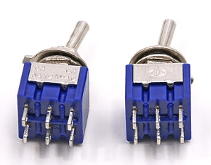
Touch buttons are input devices that are designed to detect human touch. The most common type measures capacitance, which changes when sensor element is touched by a finger (or a metallic object). The ESP32 has touch sensor pins and does not require additional circuitry to detect touch. For the Arduino and other MCUs that don’t have direct touch sensor support, touch sensor modules are available. Below an example of a common touch sensor module:
BAEASU TTP223 TTP223B Capacitive Touch Sensor Switch Module, Self-Lock Switch Button Module
The are easy to connect and to use. Compared to mechanical buttons and switches they have the advantage that they can be encapsulated within a housing, being completely protected from dust or water. Most types also allow to configure a latching or momentary behaviour, meaning the output signal remains high after a touch or not.
Key considerations
When using touch sensor modules a few aspects are worth considering. Firstly they are less suitable for low-power application, since the consumer power. They are also more vulnerable to electro-magnetic interference and generally accidental activation. Finally, there is no tactile feedback but most modules come with an integrated LED that signals the state of the switch.
Keypads
Keypads or keyboards are essentially rectangular arrangements of multiple buttons. Commonly, the buttons are of the mechanical or capacitive type. Below a picture of a typical 4×4 keypad that uses mechanical, membrane switches:
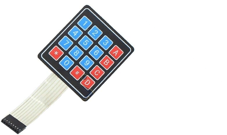
DEVMO 2PCS 4 x 4 Matrix Array 16 Key Membrane Switch Keypad Keyboard
Since the number of keys is often larger than the number of inputs available on an Arduino, they are not individually addressed. Instead a keyboard matrix addressing scheme is used. It organizes the keys in columns (C1…C4) and rows (R1…R4):
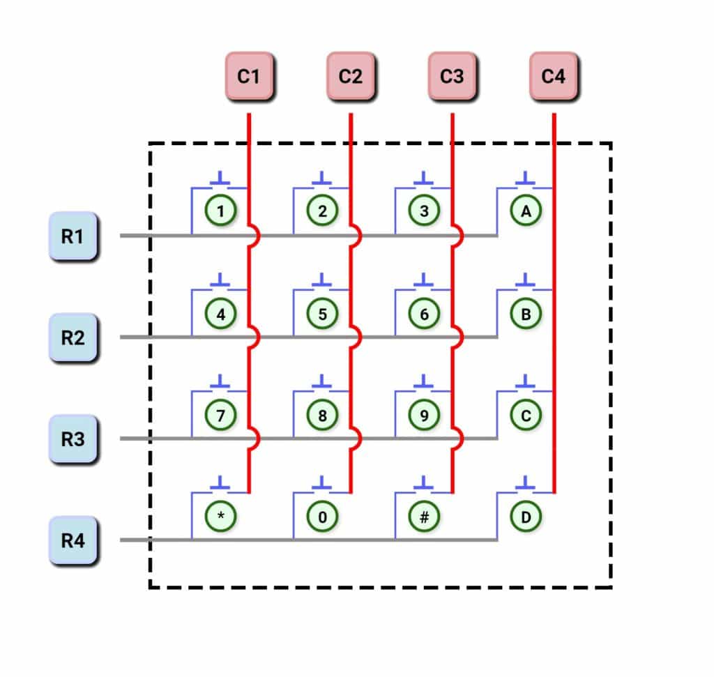
For a 4×4 keypad with 16 keys this reduces the number of needed GPIO inputs from 16 to 8. We have a tutorial on how to connect a keypad to an Arduino.
Key considerations
Keypads, especially larger ones, tend to use up many valuable GPIO pins. However, using I2C communication and a suitable IO expansion module, can eliminate this issue. An expansion module, such as the one below, needs only the two pins of the I2C bus (SCL & SDA), to control 8 I/O channels.
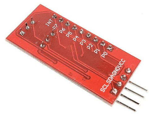
HiLetgo 2pcs PCF8574 PCF8574T IO Expansion Board I/O Expander I2C Evaluation Develop Module
The I2C Keypad library offers the readymade software to connect a 4×4, 5×3, 6×2, 8×1 or smaller KeyPad a PCF8574 based expansion module. Not only the Arduino but also the ESP32 and many other MCUs support the I2C bus.
Touchscreens
An alternative to a keypad as an input device is a touchscreen. Touchscreens are usually TFT displays, with either resistive or capacitive touch sensing. The resistive types need pressure to be applied on the screen to detect the touch. A commonly used, resistive touchdisplay is the following one from ELEGOO:
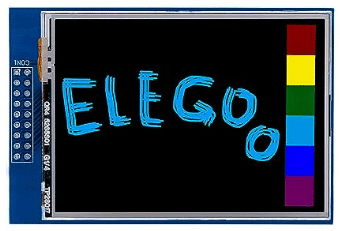
ELEGOO UNO R3 2.8 Inches TFT Touch Screen with SD Card Socket
Controlling a touchscreen from an Arduino is obviously more complex than controlling a simple keypad. However, we have a tutorial on how to interface an Arduino with a touchscreen display.
Key consideration
Apart from the increased complexity, touchscreens are generally much less robust than keypads and scratch easily. They also actively consume power while keypads are passive input devices. Finally, the computational load for running a touchscreen display is much higher than that of a keypad. That also means, that a touchscreen is generally not as responsive as a keypad.
Rotary Encoders
Rotary encoders are input devices that convert a rotation into an digital codes. They typically output two digital signals or pulses, often referred to as ‘DT’ and ‘CLK’ (or ‘A’ and ‘B’). These pulses are usually 90° out of phase. By monitoring these two signals, we can determine the amount and the direction of rotation.
Below is a common rotary encoder module suitable for the Arduino with 20 pulses per full rotation and an extra push button.
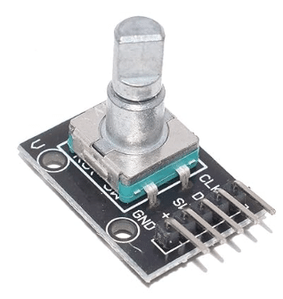
HiLetgo 5pcs 360 Degrees Rotary Encoder Module
Common use cases for rotational encoders are digital volume control, selection of (menu) functions and the monitoring of motor speed, position and direction. The are easy to use and we have a tutorial on how to how to interface a rotary encoder with an Arduino.
Key consideration
Most rotary encoders are mechanically similar to switches. Consequently, we have to consider the same potential issues as with switches, such as debouncing, pull-up resistors and logic level (3.3V vs 5V). Furthermore, if we use polling to monitor the pulses, the Arduino/code must be fast enough to not miss pulse. Finally, rotary encoders vary in their resolution (i.e., pulses per rotation). We need to select an encoder with sufficient resolution for our application.
Potentiometers
So far all the input devices presented, were digital input devices. They generate digital signals (HIGH, LOW) and are connected to the digital GPIO pins. Potentiometers, on the other hand, are analog input devices. Here is our tutorial on how to control an LED with a potentiometer.
Internally, a potentiometer is a three-terminal resistor with a sliding or rotating contact that forms an adjustable voltage divider. Typical resistance values for potentiometers are 10KΩ or 100KΩ. See an example of a commonly used 10K potentiometer below:
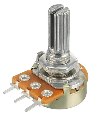
HiLetgo 20pcs WH148 Single-Joint Potentiometer 10K B10K Variable Resistors
Key consideration
Make sure to connect the potentiometer to an analog GPIO pin (A0, …) and use analogRead() to read the input value. Since the resistance of the potentiometer can change with temperature, you will find the input value to change when the potentiometer gets warmer or colder. You will also see fluctuations in the input value due to electromagnetic noise picked up by the wires. Finally, the resolution is limited by the analog-to-digital converter (ADC) of the microcontroller.
Joysticks
A joystick is composed of two potentiometers arranged in perpendicular axes (X, Y) that are controlled by a central stick or knob. Below is a common joystick module used for Arduino:
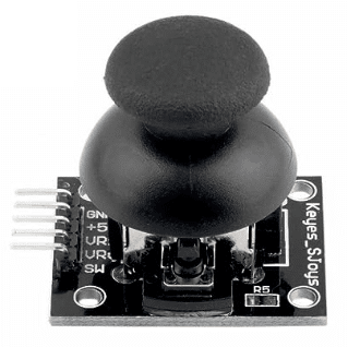
WWZMDiB 6Pcs Dual-Axis Button Joystick Module
A typical joystick provides input about its position along its axes, usually X (horizontal) and Y (vertical) as analog input values. Many of them also have an additional switch (fire button), which generates a digital input. See our tutorial on how to use a joystick with an Arduino.
Key consideration
Note that there are simplified joysticks that don’t use potentiometers but switches to indicate direction. They are digital in nature. On the other hand, there are also joysticks with more than two axis. For instance, to control X, Y and Z directions. When connecting a joystick module to your microprocessor ensure that the logic levels match (3.3V vs 5V). The analog outputs must be connected to analog inputs (A0, A1) and read via analogRead(), while the button should be connected to a digital input and read via digitalRead().
USB Mouse
You cannot directly connect a USB mouse to an Arduino and use it as an input device. You would need a USB shield, such as the one below (specifically for the Arduino board you are using):
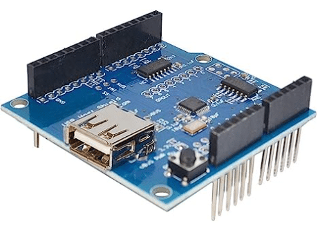
ARCELI USB Host Shield for Arduino UNO MEGA 2560
Here is a tutorial on how to connect a mouse to an Arduino using a USB shield.
Key consideration
Generally, you are better off connecting a joystick to an Arduino, instead of trying to connect a USB mouse via an USB shield. You can build your own mouse, using two rotary encoders or read the rotary encoders within an (old) mechanical mouse directly.
Summary
Here we have provided you with an overview of all the different types of input devices commonly used with Arduino and similar microcontrollers. For more details on how to connect these various devices have a look at our Articles on inputs and sensors and the links in the post. We also have an overview article on all the different types of sensors you can connect to an Arduino.
Stefan is a professional software developer and researcher. He has worked in robotics, bioinformatics, image/audio processing and education at Siemens, IBM and Google. He specializes in AI and machine learning and has a keen interest in DIY projects involving Arduino and 3D printing.