In this tutorial you will learn how to dim a high-power LED with the LD24AJTA_MINI driver and Arduino. High-power LEDs are like normal LEDs but much, much brighter. Since they need a higher current you can’t connect them directly to a GPIO pin but must use an LED driver. How to use such an LED driver, is what you will learn in the following sections.
I will use the LD24AJTA_MINI LED driver here but we also have a tutorial for the very similar LD24AJTA driver: Control Power LEDs with LD24AJTA and Arduino.
Comencemos.
Required Parts
Below the list of required parts. I used an Arduino Uno for this project but any other Arduino board, or ESP8266/ESP32 board will work just as well. However, when using an ESP8266/ESP32 board the maximal input voltage to the analog input is 3.3V and not 5V as it is for the Arduino Uno.
The provided link for the power LED, is for a white color LED but you can get other colors and different color temperatures (e.g. warm white vs cool white). You will also need a potentiometer but any potentiometer in the 50K to 5K range will be fine.

Arduino Uno

Dupont Wire Set

Tablero de pruebas

USB Cable for Arduino UNO
LD24AJTA_MINI LED Driver
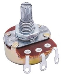
Potentiometer 10KΩ
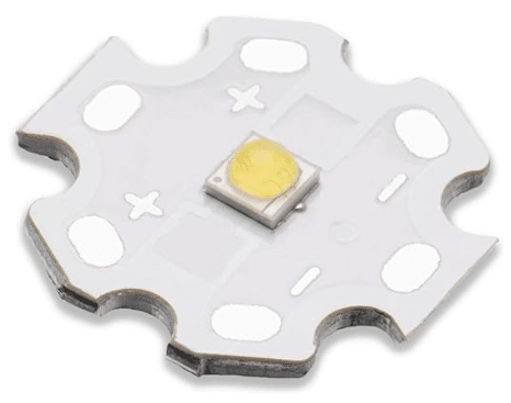
High Power LED (White)
Makerguides.com is a participant in the Amazon Services LLC Associates Program, an affiliate advertising program designed to provide a means for sites to earn advertising fees by advertising and linking to products on Amazon.com. As an Amazon Associate we earn from qualifying purchases.
High-power LEDs
You will find that high-power LEDs come in all kinds of shapes and sizes. But the smaller wattage one I am going to use here typically look like this:
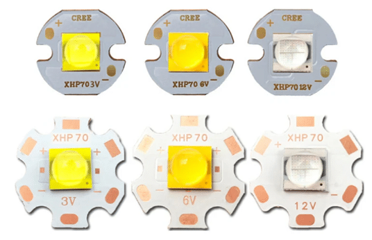
They have a disc- or star-shaped cooling plate attached, since due to their higher current (>100mA) consumption they get hot easily and need extra cooling.
In contrast, standard LEDs are typically running on 10mA to 20mA and don’t get even get warm. However, high-power LEDs are much, much brighter than normal LEDs (100x and more) and can light up a room.
The high-power LED, I am going to use here (listed above), can draw a current of up 700mA and produces up to 170 Lumen of light. That is about 170 times brighter than a normal LED.
The disadvantage over a high-power LED is that we can’t control it directly from a GPIO pin of an Arduino, since the GPIO output current is limited a maximal 40mA (and even that is better avoided). We need an LED driver and in the next section we have a closer look at some LED drivers.
Basics of LED driver boards
LED driver boards are essential components in pretty much all LED lighting systems. They provide the necessary power regulation for high-power LEDs to function optimally. These boards typically convert higher voltage (AC or DC) to a lower voltage (DC) power that is suitable for LEDs. Most importantly they also maintain a constant current flow through the LED. Without proper current regulation, LEDs can be easily damaged or may not operate efficiently.
An LED driver contains a switching regulator circuit that rapidly switches the input voltage on and off to control the output voltage. This switching action allows the driver to efficiently step down the voltage while minimizing power loss. It typically also contains an inductor that releases energy during the switching process and helps to regulate the output voltage and current. Finally it contains a current regulator that controls the amount of current flowing through the LEDs to prevent overheating and ensure consistent brightness.
Many, smaller LED driver boards utilize a common IC, the PT4115, as their core component. We will have a closer look at this IC in the next section.
PT4115
The PT4115 is a continuous conduction mode, inductive step-down converter. It can drive a single or multiple LEDs from a voltage source higher than the total LED chain voltage. The following Typical Application Circuit shows how to use the PT4115.
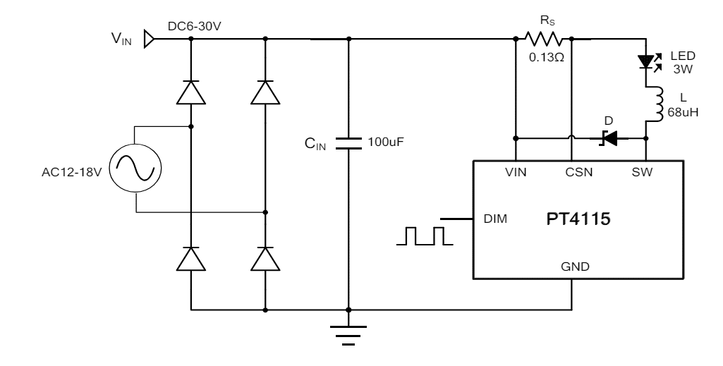
You will note that the Typical Application Circuit shows an AC power supply but all the LED driver boards we are discussing below are supporting only a DC power supply! Don’t connect them to AC voltage!
The Typical Application Circuit also shows a small Inductor (68uH) and a Resistor Rs (0.13Ω). You will recognize those hardware elements on the LED driver boards shown below.
The permissible input voltage for the PT4115 ranges from 6V to 30V and the maximum output current is 1.2A! Note that the boards listed below might list slightly different specification, either due to different recommendation or changes to the Resistor Rs, which controls the maximum output current.
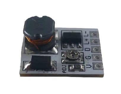
LD24AJTA_MINI
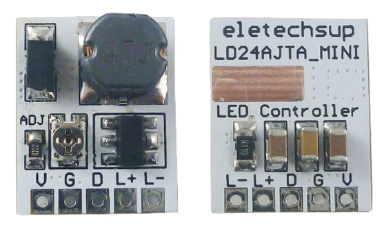
The LD24AJTA_MINI LED driver is based on PT4115. The recommended supply voltage is between 6V and 25V and it provides an externally adjustable output current of up to 910mA. Depending upon the supply voltage the LD24AJTA_MINI can deliver up 22 watts of output power (at 24V). The picture below shows the front and back of side of the board:
Pinout
The LD24AJTA_MINI LED has five pins to connect. VIN+ and GND are used to provide the supply voltage (6-25V). LED+ and LED- are the positive and negative output for the LEDs to drive. The PWM (Pulse Width Modulation) pin controls the output current and therefore the brightness of the connected LEDs.
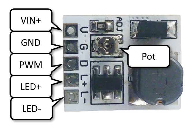
The little Potentiometer (Pot) on the board allows you reduce the maximum output current down form 910mA. So, if your LEDs are getting too hot or bright, this is the place to adjust the current. Note, however, that if a PWM signal is provided it overrides the Potentiometer setting. For more details see our tutorial: Control Power LEDs with LD24AJTA and Arduino.
Changing max current
If you need more output current, instead of less, you can swap out the Current Sensing Resistor (RCS) on the board. See the picture below.
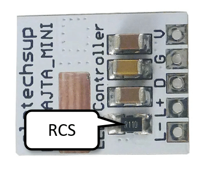
By changing the RCS resistance you can reach a maximum current of 1.2A. The following table shows the relationship between RCS value and maximum output current.
| RCS | max Iout |
|---|---|
| 1.0 Ω | 100 mA |
| 0.5 Ω | 200 mA |
| 0.2 Ω | 500 mA |
| 0.1 Ω | 1000 mA |
The default resistor is a 0.11 Ω resistor, which results in the default maximum output current of about 910 mA.
Note that there are two other boards, the LD3080SA and the LD2635MA, which look almost identical to the LD24AJTA_MINI (see the pictures in the following sections). The main difference is the lack of a Potentiometer to manually adjust the maximum output current.
LD3080SA
Like the LD24AJTA_MINI, the LD3080SA is based on the PT4115 and has essentially the same specification and pinout as the LD24AJTA_MINI (6-25V input, max output power 20W). See picture below.
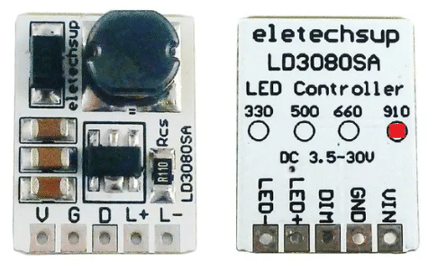
However, you can buy different versions of the LD3080SA, with different RCS resistors soldered on. As shown in the table above depending on the RCS value the maximum output current will vary. You can get a 330mA, a 500mA, a 660mA and a 910mA version, with the version marked by a red dot on the back (see above).
Note that you still can (down-)regulate the current using the PWM input (D) on the board.
LD2635MA
LD2635MA is essentially a smaller version of the LD3080SA with a fixed maximum current of 350mA. Pinout, function and hardware components are the same. See picture below.
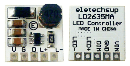
The main difference is that you typically get the LD2635MA only as the 350mA version, which might be too low a current output depending on the LED you want to drive.
In this project, you could use the LD24AJTA, LD24AJTA_MINI or the 910mA version of the LD3080SA board. All of them deliver up to 910mA output current, which is more than the 700mA the high-power LED we are using here.
In the next section, I show you how to connect the LD24AJTA_MINI to the Arduino and use its PWM output to control the LED current for dimming. The good news is that the LD3080SA or the LD2635MA would be connected and controlled exactly in the same way.
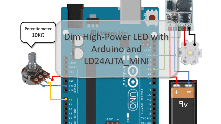
Connecting the LD24AJTA_MINI and Potentiometer to Arduino
In this section you will learn how to connect an LED driver and a Potentiometer to an Arduino to manually regulate the brightness of the high-power LED by turning the knob of the Potentiometer.
Connecting the LED driver is simple. The following basic circuit show how to supply power and connect the LEDs to the LD24AJTA_MINI driver.
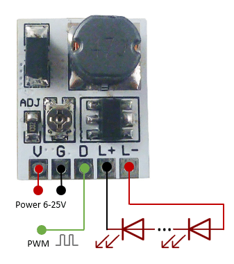
Based on the basic circuit we can connect the LD24AJTA_MINI driver to the Arduino. In the following example circuit, I am using a 9V battery as power supply for the LED driver. But any power supply with 6-25V and sufficient current (700mA) could be used.
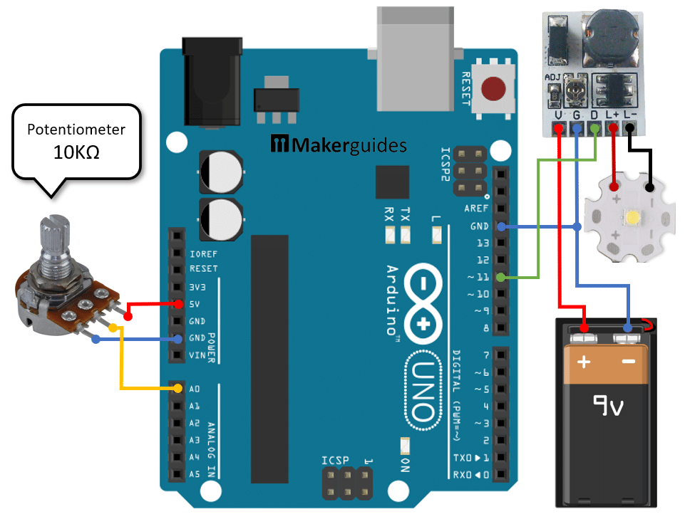
In the first step, we connect the battery to the LED driver. The positive pole (+) needs to be connected to the V pin (red wire) and the negative pole (-) of the 9V battery must be connected to the G pin (blue wire) of the LED driver.
Now, we connect the negative pole of the 9V battery also to the GND pin of the Arduino. This is important! Arduino and LED driver must share the same ground.
Since, we want to control the brightness of the LED we need to use the PWM pin (D) of the LED driver. Connect it to pin 11 of the Arduino (green wire). Any other PWM output pin (~3, ~5, …) of the Arduino would work as well. Just make sure to adjust the code below accordingly.
Next, we connect the high-power LED to the L+ and L- pins of the LED driver (red and black wire). Watch out for matching polarity here!
Finally, we connect the potentiometer to the Arduino. The +5V output of the Arduino needs to be connected to the right or left pin of the potentiometer. The GND pin must be connected to the opposite pin (left or right). And the middle pin (yellow wire) will be connected to the analog input A0 of the Arduino.
In the next section we write the code to dim the brightness of the LED by turning the knob of the potentiometer.
Code for Controlling the Brightness via Potentiometer
In the code snippet above, we control the brightness of a high-power LED using an Arduino, an LD24AJTA_MINI LED driver, and a Potentiometer. This setup allows for adjusting the brightness of the LED by varying the analog input from the Potentiometer.
// Regulate brightness of high-power LED
// via LED driver board and Potentiometer

const byte ledDriverPin = 11;
const byte potPin = A0;

void setup() {
  pinMode(ledDriverPin, OUTPUT);
}

void loop() {
  int pot = analogRead(potPin);
  int brightness = map(pot, 0, 1023, 0, 255);
  analogWrite(ledDriverPin, brightness);
  delay(100);
}
Let’s break down the code to understand how it works in detail.
Constants and Variables
We start by defining two constants: ledDriverPin which specifies the pin connected to the PWM input (D) of the LED driver board, and potPin which specifies the analog pin connected to the Potentiometer.
If you want to connect the LED driver to a different Arduino GPIO pin, you can do this here. Just make sure you are using a PWM pin.
const byte ledDriverPin = 11;
const byte potPin = A0;
Setup function
En el setup() function, we set the ledDriverPin as an output pin since we will be using it to control the LED brightness via a PWM signal.
void setup() {
  pinMode(ledDriverPin, OUTPUT);
}
Loop function
El loop() function continuously reads the analog input from the Potentiometer using analogRead(). However, the analog input ranges from 0 to 1023 but the PWM output (LED brightness) ranges only from 0 to 255.
We therefore use the map() function to convert the analog input value from the range of 0 to 1023 to a brightness value between 0 and 255. The calculated brightness value is then written to the ledDriverPin using analogWrite(), which controls the LED brightness by generating an appropriate PWM signal.
We don’t need to do this super fast and use short delay of 100 milliseconds to ease the computational load. This also will make brightness transitions a bit smoother but slower.
void loop() {
  int pot = analogRead(potPin);
  int brightness = map(pot, 0, 1023, 0, 255);
  analogWrite(ledDriverPin, brightness);
  delay(100);
}
If you need more details on how to read potentiometer values, have a look at our tutorial on How use Arduino to control an LED with a Potentiometer.
And that’s it! With the above code and circuit you can dim high-power LEDs with up to 22W.
Conclusión
In this tutorial you have learned how to dim a high-power LED using the LD24AJTA_MINI driver and an Arduino via a Potentiometer. You now understand why an LED driver is needed, if you want to control high-power LEDs. We also discussed the very similar LD24AJTA, LD3080SA and the LD2635MA LED driver boards and their differences.
With the provide examples you should have sufficient information to build more advanced applications. For instance, controlling the brightness of a high-power LED depending on ambient light using an LDR sensor, or constructing a motion-activated, surveillance lighting solution.
If you have further questions, have a look at the following FAQ section and don’t hesitate to ask ; )
Frequently Asked Questions
Q: How do I connect the LD24AJTA_MINI driver to the Arduino?
A: To connect the LD24AJTA_MINI driver to the Arduino, simply wire the input and output pins according to the provided circuit diagram. Ensure proper power supply and ground connections.
Q: Does the LD24AJTA_MINI driver support dimming functions for high-power LEDs?
A: Yes, the LD24AJTA_MINI driver supports dimming functions through PWM control, allowing you to adjust the brightness levels of high-power LEDs according.
Q: What is the difference between the LD24AJTA_MINI LED driver and the LD24AJTA, LD3080SA or the LD2635MA?
A: They are all essentially the same drivers all based on the PT4115 chip. The main difference is that the LD24AJTA boards have a potentiometer that allows you to regulate the maximum output current. However, if you use a PWM signal to control the driver, you will not need this.
Q: Are there any specific safety precautions to consider when working with high- power LEDs?
A: When working with high-power LEDs, make sure that you provide proper cooling. Power LEDs, even with heatsinks attached, can get very hot!
Q: Can I use the LD24AJTA_MINI driver in conjunction with sensors for automated lighting control?
A: Yes, you can integrate sensors such as motion sensors, light sensors, or temperature sensors with the LD24AJTA_MINI driver and Arduino to enable automated lighting.
Q: Can I use a different LED driver board instead of LD24AJTA_MINI?
A: Yes, you can use a different LED driver board as long as it is compatible with the high-power LED you are using and can be controlled by an Arduino.
Q: Do I need any additional components to dim the high-power LED?
A: Apart from the Arduino, LD24AJTA_MINI LED driver, and Potentiometer, you may need a suitable power supply and appropriate wiring connectors.
Q: How can I protect the high-power LED from overheating?
A: To prevent overheating, ensure proper heat dissipation by using a heatsink or a fan if necessary. Monitor the temperature of the LED during operation.
Q: Can I control the LED brightness remotely using Bluetooth or Wi-Fi?
A: Yes, you can integrate Bluetooth or Wi-Fi modules with the Arduino to control the LED brightness remotely through a mobile app or a web interface.
Q: What is the maximum power rating supported by the LD24AJTA_MINI LED driver?
A: The LD24AJTA_MINI LED driver can support high-power LEDs with a maximum power rating of 22 watts.
Stefan is a professional software developer and researcher. He has worked in robotics, bioinformatics, image/audio processing and education at Siemens, IBM and Google. He specializes in AI and machine learning and has a keen interest in DIY projects involving Arduino and 3D printing.