In this tutorial you will learn how to control high current power LEDs with the LD24AJTA driver and Arduino. Standard LEDs are typically used as indicator lights and can be directly driven from an Arduino GPIO pin. However, if you want to control super bright LEDs, such as Cree LEDs a bit more work is needed.
In this project we will use an LD24AJTA LED driver board to control such high power, super bright LEDs with an Arduino. Note that we also have a tutorial for the very similar LD24AJTA_MINI: Dim High-Power LED with Arduino and LD24AJTA_MINI.
Comencemos.
Required Parts
Below the list of required parts. I used an Arduino Uno for this project but any other Arduino board, or ESP8266/ESP32 board will work just as well. The provided link for the power LED is for a white color LED but you can get all kinds of colors and even different color temperatures (e.g. warm white vs cool white).
LD24AJTA LED Driver
High Power LED (White)

Arduino Uno

Dupont Wire Set

Tablero de pruebas

USB Cable for Arduino UNO
Makerguides.com is a participant in the Amazon Services LLC Associates Program, an affiliate advertising program designed to provide a means for sites to earn advertising fees by advertising and linking to products on Amazon.com. As an Amazon Associate we earn from qualifying purchases.
Standard versus Power LEDs
In this section, we look at power LEDs, how they compare to standard LEDs and what you need to drive them.
Standard LEDs
You are probably familiar with the small 5mm or 3mm standard LEDs that are commonly used as indicators lights or in toys. The picture below shows a typical 5mm, white, standard LED.
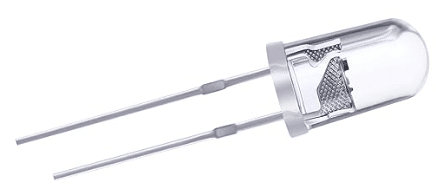
These LEDs consume very little power with around 20mA at 3V. You can directly control them from a GPIO pin of an Arduino, which is great. However, they are not very bright; maybe up to 1 Lumen, which is sufficient for an night light but not much beyond. See our tutorial on How to build a motion activated night light, for an example application.
Power LEDs
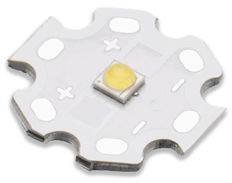
Power LEDs, on the other hand, are much, much brighter. For instance, a single, high power Cree LED can generate up to 350 Lumen, that is 350 times brighter than the standard LED shown above!
And, while power LEDs are not much bigger than standard LEDs, they draw a lot more current and get a lot hotter, which is why they typically need a heatsink or extra cooling. For instance, the high power LED we listed in the required parts, draws up to 700mA and comes with a star-shaped Aluminum plate attached, as a heatsink.
Note that the actual LED is the small, yellow blob in the middle of the plate, which has about the same diameter as a 3mm standard LED. Most commonly these LEDs use a 3535 SMD LED chip and they come with different colors, viewing angles, light temperature and heatsinks.
The technical specs of the high power LED we are using here, are as follows:
- current up to 700mA (continuously)
- peak pulse current 1000mA (at 1/10 duty cycle and 0.1ms pulse width)
- voltage: 3.2-3.6V
- power: 3W
- 170 Lumen at 700mA (typical)
An Arduino GPIO pin can deliver a maximum current of up to 40mA, which is much lower than the 700mA current a high power LED will draw at maximum brightness. Therefore, you cannot connect a power LED directly to an Arduino but must use an LED driver.
In the next section we have a look at such a driver; the LD24AJTA LED driver.
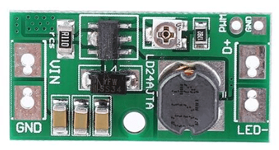
Introducing the LD24AJTA LED driver
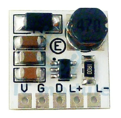
The LD24AJTA driver board takes 6-25V as input and outputs a regulated current between 30 and 900mA. The picture below shows the Pinout of the board.
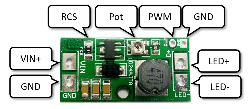
The board contains a buck converter that steps down the input voltage and a PT4115 LED driver IC that regulates the current and keeps it at a constant level. This is important, since the resistance of power LEDs changes when they get hot, which can result in overheating if the current is not controlled.
The input voltage (DC) is provided at the VIN+ and GND pin. A potentiometer (Pot) allows to adjust the output current manually. But there is also a PWM input that takes a PWM signal between 100Hz and 20kHz to control the output current electronically.
The following list shows the detailed spec of the LD24AJTA:
- Controller Step-down Constant Current
- 6-25V 900mA Step-down
- LED Driver with 5000:1 Dimming
- Working voltage : DC 6-25V
(for 6V 9V 12V 18V 24V LED or LED strip) - Output Current: 30-900MA
By changing the RCS resistance, the maximum current can reach 1200MA - Maximum output power: 20W
- Current regulation
(through adjustable resistance or through PWM control) - Single pin on/off and brightness control using DC voltage or PWM
- Up to 1MHz switching frequency
- Typical 5% output current accuracy
- Inherent open-circuit LED protection
- High efficiency (up to 97%)
- High-Side Current Sense
As mentioned above, the output current of the LD24AJTA driver can be controlled manually or electronically. In the next two sections we have a look how that is done.
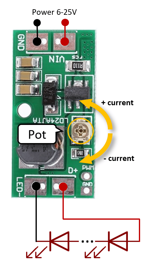
Manual Current Control
For manual current control just connect the LD24AJTA to a power supply with 6..25V and one or multiple LEDs in series to the LED output. The output current can then be changed by turning the potentiometer (Pot) to the right or left.
Electronic Current Control
To control the output current of the LD24AJTA you can provide a PWM signal at the PWM input. Power supply and LEDs are connected in the same way as before.
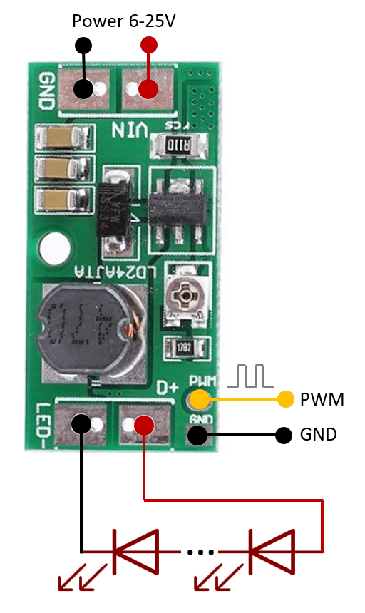
Note: when you use the PWM input to control the current the potentiometer settings are essentially ignored. In other words you cannot control the output current manually and electronically at the same time.
PT4115 driver IC
The LD24AJTA uses the PT4115 LED driver IC as shown in the schematics below:
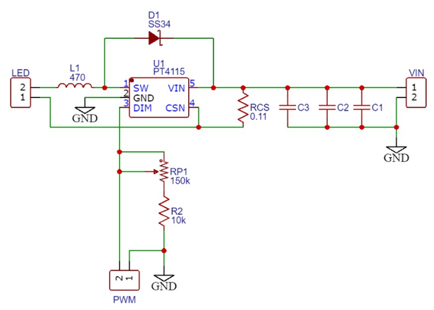
If you look closely at the schematics, you will see that potentiometer (RP1) is connected to the DIM pin of the PT4115 and not the current sense circuit (RCS). Therefore the PWM signal will take precedence over the current setting of the potentiometer.
If you use the PWM input but want a maximum current other than 900mA, you can replace the RCS resistor on the board with a suitable value. RCS stands for: Resistor for Current Sensing.
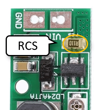
You can calculate the required resistor value as Iout = 0.1/RCS. The table below shows some common resistor values and corresponding output currents. The default resistor is a 0.11 Ω resistor, which results in a maximum output current of about 900 mA.
| RCS | max Iout |
|---|---|
| 1.0 Ω | 100 mA |
| 0.5 Ω | 200 mA |
| 0.2 Ω | 500 mA |
| 0.11 Ω | 900 mA |
| 0.1 Ω | 1000 mA |
In the next section we connect the LD24AJTA to the Arduino and use its PWM output to control the LED current for dimming.
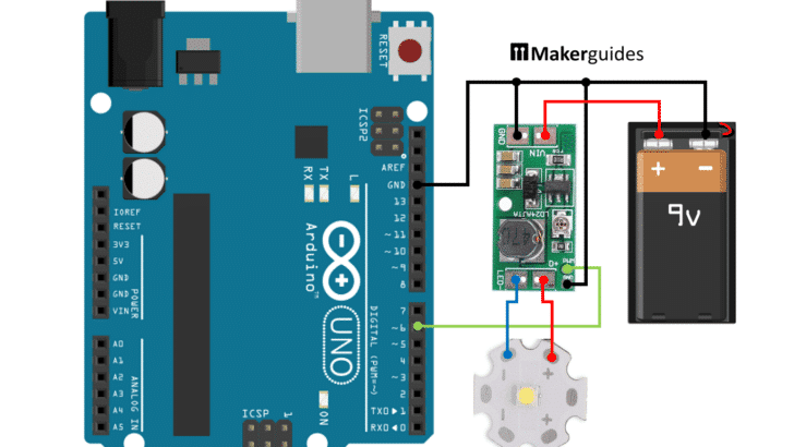
Connecting the LD24AJTA and Arduino
Connecting the LD24AJTA to the Arduino is very simple. First connect the GND pins of the LD24AJTA and the power supply (battery) to the GND pin of the Arduino (black wires). According to the schematics, it may be sufficient to connect only one of the GND pins LD24AJTA but to be safe, I connected both of then to GND. See the wiring picture below.
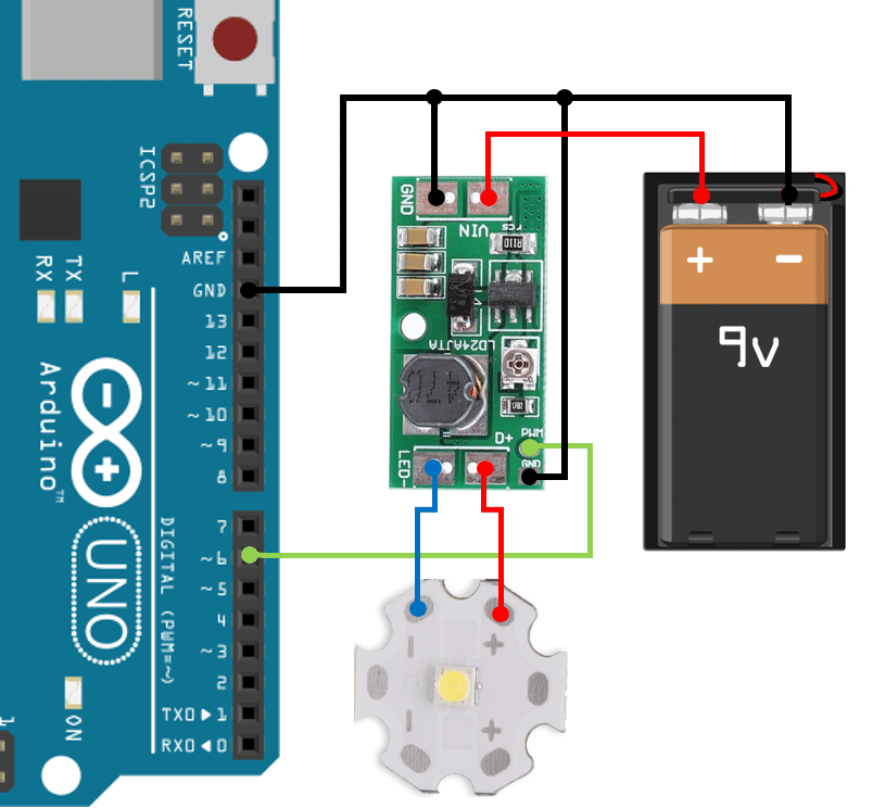
Next connect the plus pole of the power supply (battery) to the VIN input of the LD24AJTA. I am using a 9V battery here, which will be fine for trying the circuit out. But for a serious application you will need to use a power supply that can deliver a continuous current of 1A. A typical 9V battery is limited to 600mAH, which is sufficient to light up the LED but it won’t last very long. You can get rechargeable 9V batteries with 1000mAH capacity (which is what I actually use), and they will last a bit longer.
Then we need to connect the PWM input of the LD24AJTA to a PWM output pin of the Arduino (green wire). I pick pin 6 here, but any of the PWM pins ~3, ~5, ~6, ~9, ~10 ~11, will work.
Finally, we connect the power LED to the LED+ and LED- outputs of the LD24AJTA (blue and red wires). Make sure that you connect in the correct polarity.
Next we write the code to control the LED.
Code to control Power LEDs with Arduino
With the LD24AJTA driver connected, the code to control a power LED is no different from controlling a standard LED. Below is the common blink code that switches the LED on for one second and then off for another second.
// Switching LED on and off
const byte ledPin = 6;

void setup() {
  pinMode(ledPin, OUTPUT);
}

void loop() {
  analogWrite(ledPin, HIGH);
  delay(1000);
  analogWrite(ledPin, LOW);
  delay(1000);
}
If you need help with this code have a look at our tutorial on How To Blink An LED Using Arduino .
Similarly, dimming the LED uses the usual analogWrite() and Pulse Width Modulation (PWM) to slowly increase the brightness of the LED from 0 to 255.
// Dimming the LED
const byte ledPin = 6;  // PWM

void setup() {
  pinMode(ledPin, OUTPUT);
}

void loop() {
  for (int b = 0; b < 256; b++) {
    analogWrite(ledPin, b);
    delay(100);
  }
}
If you want to control the brightness of the LED based on external sensors have a look at the example in How use Arduino to control an LED with a Potentiometer and How to detect light using an Arduino.
And that’s it. Now you know how to control super bright, high current power LEDs with an Arduino using the LD24AJTA driver board. There are a two other options, we discuss in the next section.
Other LED drivers boards
There are three other LED drivers boards, I would like to mention. First there is the LD24AJTA_MINI, which is essentially the same as the LD24AJTA, just with a slightly smaller form factor. See the following picture:
We have a tutorial on that LED driver as well: Dim High-Power LED with Arduino and LD24AJTA_MINI.
The next interesting board is the LD06AJSA/B, depicted below.
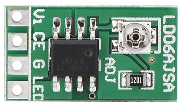
This is a good option if you want to drive hight current LEDs, since it can output up to 1500mA, while the LD24AJTA is limited to 1000mA.
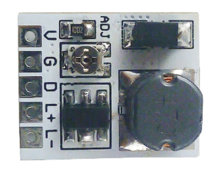
An option for less power-hungry LEDs is the LD2635MA, which is a smaller and cheaper than the LD24AJTA and the LD06AJSA, but can output only up to 350mA. See a picture of that board below.
All three boards support manual or electronic control of the output current. The following table provide a quick comparison of the three options:
| Conductor | Vin | max Iout |
|---|---|---|
| LD06AJSA/B | 2.8-6V | 1500mA |
| LD2635MA | 5-27V | 350mA |
| LD24AJTA | 6-25V | 900mA |
Using power LEDs without driver
If you don’t want to use an LED driver, there are power LEDs with an integrated current limiting resistor that you can directly connect to a power source. For instance, the power LED below runs on 5V and has an integrated 68Ω resistor.
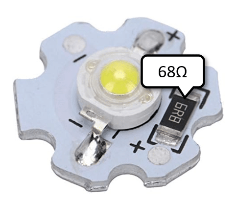
However, they are typically limited to lower currents and not as bright as the LED listed in required parts. Despite the lower current you still can’t drive them directly from a GPIO pin of an Arduino and therefore you will still need some additional circuit to switch them electronically (e.g. MOSFET, Transistor).
Conclusión
In conclusion, we have successfully learned how to control high current, super bright power LEDs using the LD24AJTA LED driver and Arduino. By understanding the components required and the connections needed, we were able to create a functional circuit to regulate the brightness of the LEDs.
Have fun extending the basic circuit with additional functionalities!
Frequently Asked Questions
Q: How do I connect the LD24AJTA LED driver to the Arduino?
A: To connect the LD24AJTA LED driver to the Arduino, simply wire the input and output pins according to the provided circuit diagram. Ensure proper power supply and ground connections for seamless operation.
Q: Is it possible to use multiple LD24AJTA LED drivers for controlling multiple power LEDs?
A: Yes, you can use multiple LD24AJTA LED drivers to control multiple power LEDs simultaneously. This allows for scalability and flexibility in your lighting projects.
Q: How can I protect the LD24AJTA LED driver from overcurrent or overheating?
A: To protect the LD24AJTA LED driver from overcurrent or overheating, you can add external current-limiting resistors, heat sinks and cooling fans.
Q: Does the LD24AJTA LED driver support dimming functions for power LEDs?
A: Yes, the LD24AJTA LED driver supports dimming functions through PWM control, allowing you to adjust the brightness levels of power LEDs according to your project requirements.
Q: Are there any specific safety precautions to consider when working with high current power LEDs and the LD24AJTA driver?
A: When working with high current power LEDs and the LD24AJTA driver, make sure that you provide proper cooling. Power LEDs, even with heatsinks attached, can get very hot!
Q: Can I use the LD24AJTA LED driver with RGB power LEDs for color mixing?
A: Yes, the LD24AJTA LED driver can be used with RGB power LEDs for color mixing applications. By controlling the intensity of each color channel, you can achieve a wide range of colors.
Q: Can I use the LD24AJTA LED driver in conjunction with sensors for automated lighting control?
A: Yes, you can integrate sensors such as motion sensors, light sensors, or temperature sensors with the LD24AJTA LED driver and Arduino to enable automated lighting control based on environmental conditions or user interactions.
Stefan is a professional software developer and researcher. He has worked in robotics, bioinformatics, image/audio processing and education at Siemens, IBM and Google. He specializes in AI and machine learning and has a keen interest in DIY projects involving Arduino and 3D printing.