In this article you will learn how to control an Air-Conditioner via IR with an ESP32 or ESP8266 microcontroller.
Most, modern Air Conditioning units come with a remote that sends Infrared (IR) signals to control the unit. However, often the functionality of the remote and the Aircon is limited. What if you want to switch on the Aircon at a specific time? What if you want to regulate the Aircon depending on the weather forecast? Or what if you want to control the Aircon from a different room? Maybe you simply lost your remote and want to build a more powerful replacement?
Note that as of January 2024 the IRRemoteESP8266 library used to generate the IR signals for controlling an Aircon does not compile for the ESP32 and Arduino 3.0.0. I tried, but could not get it working. However, once the library is fixed, the code in this article should work for the ESP32 again.
All this and more can be achieved if we use a microcontroller to control the Aircon ourselves. Let’s get started.
Required Parts
This section lists the required parts. Apart from an ESP32 or ESP8266 and some smaller parts, you will need an Aircon that can be controlled with Infrared Signals. You can find the list of supported Aircons here.
As for the microcontroller, I will specifically use the ESP8266 ESP-12F Mini (WEMOS LOLIN D1 mini) listed below but most ESP8266 and ESP32 boards should work as well. I also listed the ESP32 lite because of the low price and the battery connector with recharging capability. That would come in handy, if you want to build your own remote that runs on battery power.
Depending on what version of the project your are building, you will need only a subset of the parts listed here.
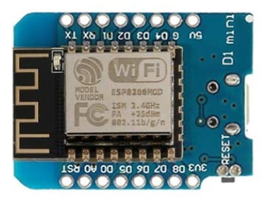
ESP8266 ESP-12F Mini
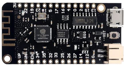
ESP32 lite
USB Data Cable

Dupont Wire Set

Tablero de pruebas

Resistor & LED kit
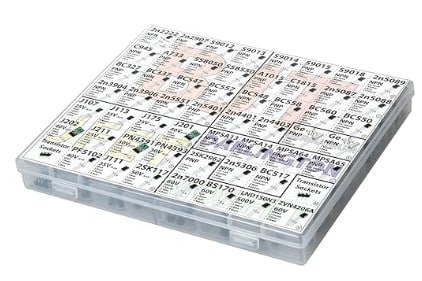
Transistor Kit
IR Receiver Transmitter
IR Transmitter Diode
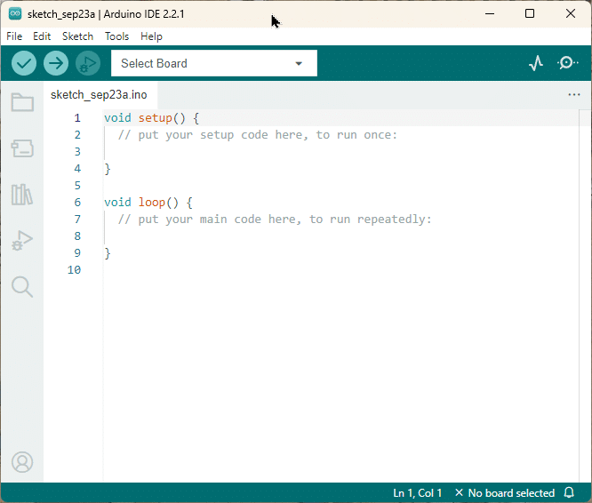
Arduino IDE
Makerguides.com is a participant in the Amazon Services LLC Associates Program, an affiliate advertising program designed to provide a means for sites to earn advertising fees by advertising and linking to products on Amazon.com. As an Amazon Associate we earn from qualifying purchases.
Infrared Technology and Air-Conditioners
Infrared (IR) technology is widely used in various applications, including remote controls for electronic devices like televisions, DVD players, and air conditioners. It allows for wireless communication between devices by transmitting signals in the form of infrared light.
Air conditioners, being one of the most common household appliances, often come with a remote control that utilizes IR technology. These remotes send specific IR signals to the air conditioner unit to control its functions, such as adjusting the temperature, fan speed, and mode.
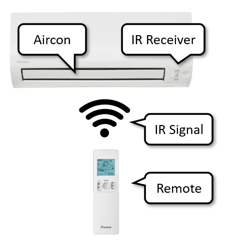
Air conditioners are equipped with an IR receiver that can detect and interpret these signals. When a command is received, the air conditioner responds accordingly, either by changing the temperature, adjusting the fan speed, or performing any other action associated with the command.
If you want to learn more about infrared signals and how to generate them have a look at our tutorials on How to build a universal, programmable IR remote, How to control an ESP32 with an IR Remote, and How to Control a Servo with an IR Remote.
Supported Aircons
It’s important to note that different air conditioner models and brands may use different IR protocols and codes. Therefore, before proceeding with the project, you should identify the brand of your air conditioner. We will be using the IRRemoteESP8266 library and the list of supported Aircons can be found here.
Once you verified that your Aircon is supported, you can proceed with connecting the ESP32/ESP8266 to an IR diode and programming it to send the appropriate signals. This will allow you to control your air conditioner remotely using a web interface.
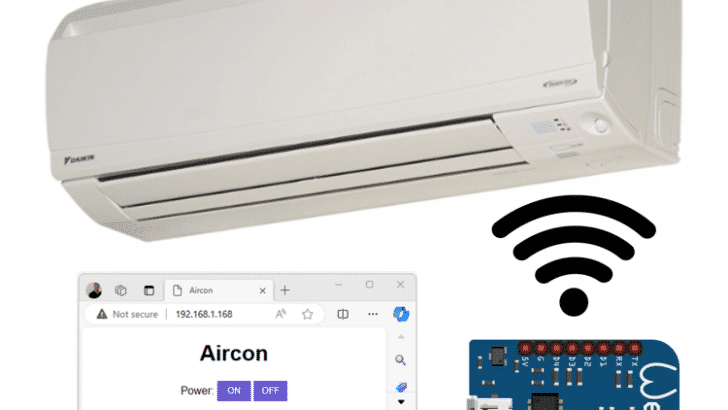
Overall System
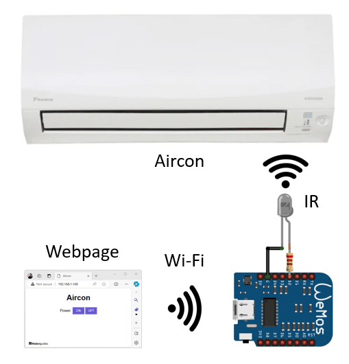
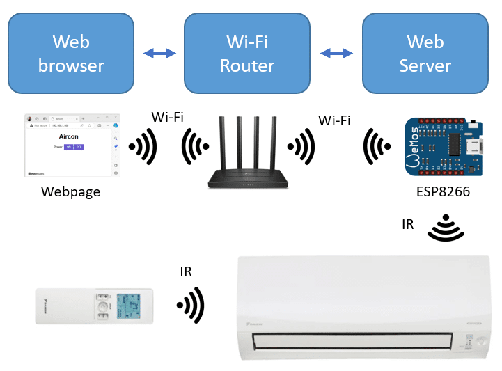
The picture below shows the overall system we are going to build. A Webpage running in a Web browser that controls the ESP32/ESP8266 via Wi-Fi, which itself controls the Aircon using IR signals.
In the next section, I will show you how to connect the ESP32/ESP8266 to an IR transmitter
Connecting the ESP32/ESP8266 to an IR transmitter
To send Infrared (IR) signals we need to connect the ESP32 or ESP8266 to an IR Transmitter. In the following I will show you three different ways to do this. The first one, is the simplest and uses one of those handy IR transmitter modules. For the second circuit, we will use a IR Transmitter Diode and a Resistor, which is a bit more work but can give us better range. The last circuit uses an additional MOSFET, which allows us to increase the range even further.
IR Transmitter Module
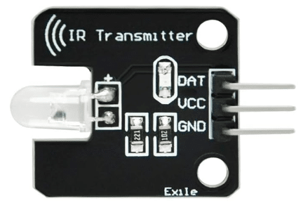
The easiest way is to use a IR Transmitter module. These modules are very simple and typically consist of an IR Diode and a resistor on a breakout board. They usually come with three pins, ground (GND or ‘-‘), power (VCC o r’+’) and signal (S or DAT). See the module below.
Connecting the IR Transmitter module
Connecting the module is straightforward. Connect Ground (G) of your ESP32/ESP8266 to the minus pin (-/GND) of the module (black wire). Then connect a GPIO pin (here we use D2) to the signal (S/DAT) pin of the module (yellow wire) And finally connect +5V (or +3.3V) of your microcontroller to the middle pin (+/VCC) of the module (red wire). Note: don’t connect the module to the TX or RX pins. This can interfere with the serial communication.
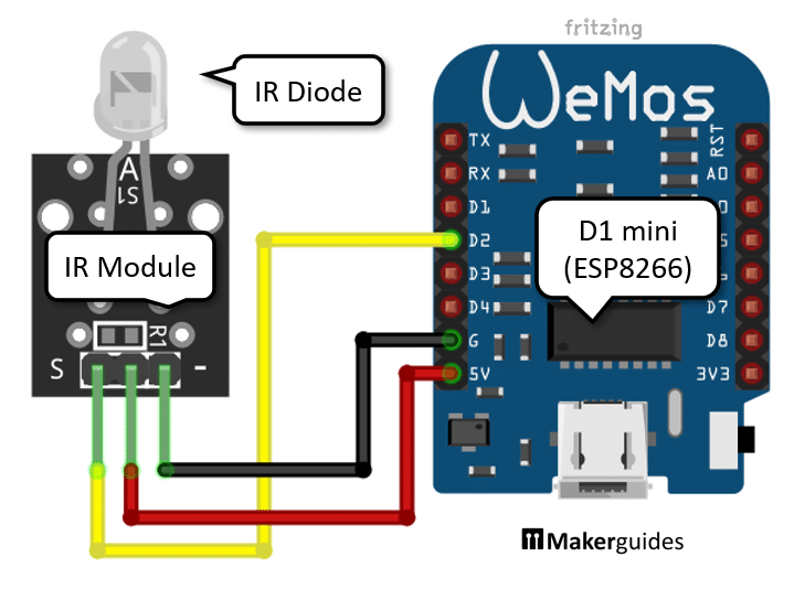
In the example circuit above, I am using a Wemos Lolin D1 mini that offers a 5V or 3.3V output. Which one you are using to power the module usually does not matter. The 5V or 3.3V input to the IR module is sometimes not used at all or is only used to indicate power or signal transfer. It generally does not affect the range of IR transmitter.
While this works and is nice to test out the function the range is rather limited. I get between 1 and 2 meters of range and it will depend on the resistor on the module. Some modules will give you much greater range but they are probably using the wrong circuit. See next section.
Modules without current limiting resistor
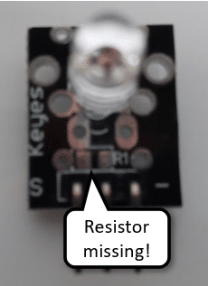
Watch out! Some cheap modules don’t have current limiting resistor, which results in the IR Diode drawing about 180mA of current. This is way too high for a GPIO output of a ESP266, which should be around 10mA! If you connect these boards you get excellent range but chances are that you are going to damage your board!
Here is a picture of such a module. If you look closely at the picture below you can see that Resistor R1 is missing and the board has only an IR Diode. You can use those boards but you have to add a resistor to the circuit.
In the next section, I show you how to connect the IR Transmitter diode and a resistor yourself. That gives us better control over current and range.
IR Transmitter Diode and Resistor
As you can see below, the circuit that uses an IR Transmitter Diode and a Resistor is still very simple. Connect the shorter pin of the IR Diode to Ground and the longer pin to the Resistor. The other pin of the Resistor is the connected to a GPIO output, here I pick D2.
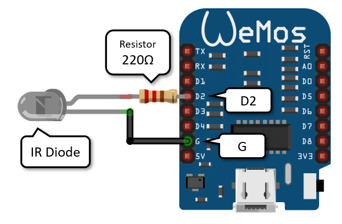
We can calculate the required resistor value as follows. We have 3.3 Volts as GPIO output, we want to draw no more than 10 mA, and the IR Diode has a forward voltage of 1.2V to 1.5V (lets make that 1.3V). So for a 220Ω resistor we get a current of 9mA:
(3.3V – 1.3V)/220Ω = 9mA
Since the IR Signal is a short pulse, we could go as low as 100Ω, for which we would get (3.3V – 1.3V)/100Ω = 20mA. This will increase the range a bit but it gets risky. A better solution would be to drive the IR Diode via a transistor or MOSFET. And that is what we are going to do in the next section.
IR Transmitter Diode and MOSFET
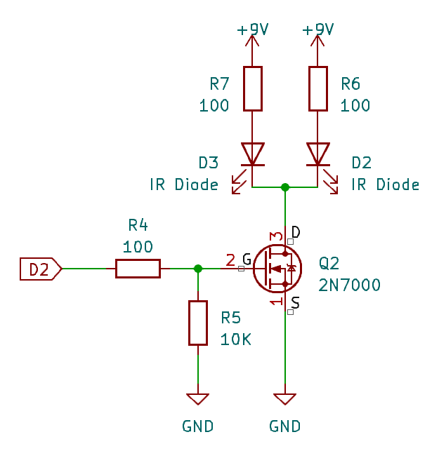
The range of our IR Transmitter is limited because we can only safely deliver 10mA to the IR Diode, when using a GPIO output of an ESP8266 directly. The IR Diode itself could by powered with up 100mA and that would increase the range of our transmitter dramatically. The following schematic shows, how we can do this.
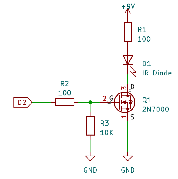
In this circuit the IR Diode is connected to a 9V battery with a current limiting resistor R1 of 100Ω. That gives us a current of (9V-1.3V)/100Ω = 77mA through the IR Diode, which is well in its limit of 100mA. With this setup, I get a range of around 8 to 10 meters.
The MOSFET acts as a switch. If the GPIO output (D2) of the ESP8266 goes high, the Gate (G) of the MOSFET opens the connection from Drain (D) to Source (S) and current can flow from the 9V battery, through the IR Diode to Ground (GND).
The 2N7000 MOSFET, I am using here, can switch up to 60V and 200mA continuously. That is sufficient for the 70mA of current our IR Diode draws.
The 100Ω resistor (R2) in the circuit is just another current limiting resistor to protect the GPIO. The second resistor (R1) with a value of 10KΩ, is a pulldown resistor that ensures that the MOSFET switches off, when the gate is not connected. If you want to learn more about MOSFETS and how use them to control electrical loads have a look at our tutorial How To a Control Fan using Arduino.
Complete Circuit on Breadboard
The picture below shows the complete circuit on a breadboard.
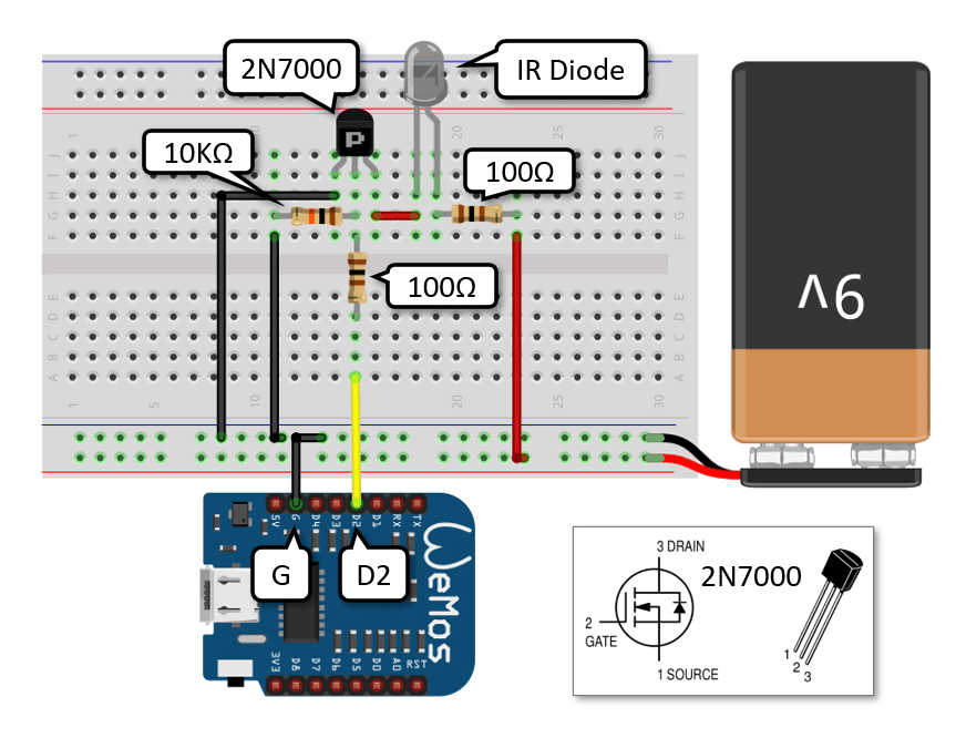
The breadboard circuit follows the schematic presented above. Start by inserting the MOSFET and the IR Diode into the breadboard. Watch our for the correct orientation of the 2N7000 and the IR Diode. Connect the 9V battery last and watch out for correct polarity. Also don’t forget that the battery and the ESP8266 must have common ground (Ground wire of ESP8266 connected to battery)!
To test the circuit you could use the blink sketch and a normal LED first before running the much more complex program, we will discuss in the next sections. Let’s start by the Webpage we need to control our Aircon.
Webpage for Remote Control
We want control our ESP32/ESP8266 via a Webpage. Webpages are typically built using the HTML language. The following HTML code describes the layout, colors and content of our Webpage.
<!DOCTYPE html>
<html>
<head>
  <title>Aircon</title>
  <style>
    body { text-align: center; font-family: Arial, sans-serif; }
    button { background-color: slateblue; color: white; border: none; width: 50px; height: 30px; }
    button:hover { background-color: darkslateblue; }
    button:active { background-color: mediumslateblue; }
  </style>
</head>
<body>
  <h1>Aircon</h1>
  <p>Power:
    <a href="/power/on"><button>ON</button></a>
    <a href="/power/off"><button>OFF</button></a>
  </p>
</body>
</html>
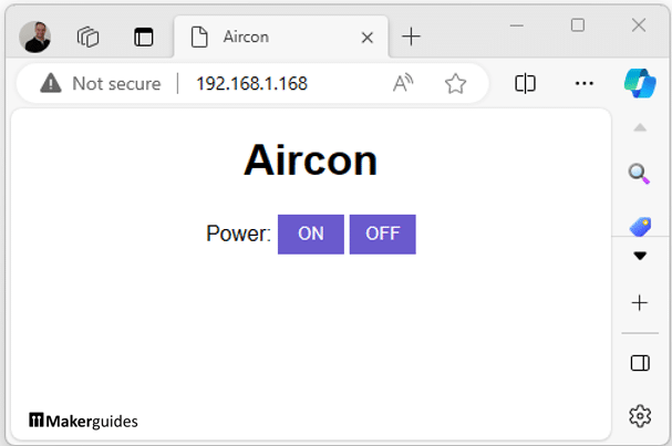
If you would copy this HTML code into a file named “test.html” and then load it into your web browser via Drag&Drop, you would see the following Webpage.
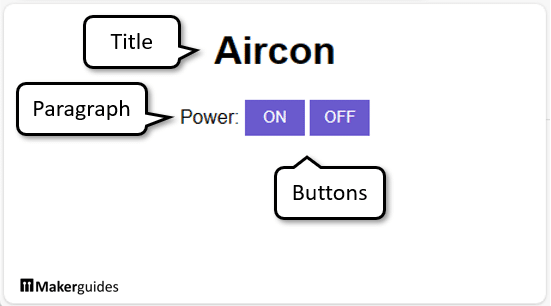
You can easily identify the elements in the HTML code and the corresponding elements on the Webpage. The Title is in the “h1” tag, “p” defines the Paragraph, which contains the text “Power” and two “button” elements with Hyperlinks “a“. The “style” section specifies the colors and layout of the page. If you want to learn more about HTML here is a good HTML Tutorial.
To show this Webpage within a Web browser we need to run a Webserver that serves this page to the browser. This Webserver will run on our ESP32/ESP8266 and we will discuss that code in the next section.
Programming the ESP32/ESP8266 for Air-Conditioner Control
Below is the complete code that allows you to control an Air-Conditioner over Infrared using a Webpage that is served by a Webserver running on you ESP32 or ESP8266. It is a larger chunk of code but we will break it into manageable pieces and explain it in detail. Just have a look first to get an overview.
Note that this code is for a DAIKIN aircon. But you can adjust the code easily to your aircon by changing the relevant communication protocol (look for the variable ac.next.protocol in the code). You can find a list of the supported Aircons here.
// Control Aircon via Infrared Signals using a Webpage
// served by a Webserver running on an ESP32/ESP8266

#if defined(ESP8266)
#include "ESP8266WiFi.h"
#elif defined(ESP32)
#include "WiFi.h"
#else
#error "This ain't a ESP8266 or ESP32"
#endif

#include "Arduino.h"
#include "IRremoteESP8266.h"  // ESP32 and ESP8266
#include "IRac.h"
#include "IRutils.h"


const int irPin = D2;
const char* ssid = "*****";
const char* password = "*****";

const char* html = R""""(
HTTP/1.1 200 OK
Content-type:text/html

<!DOCTYPE html>
<html>
<head>
  <title>Aircon</title>
  <style>
    body { text-align: center; font-family: Arial, sans-serif; }
    button { background-color: slateblue; color: white; border: none; width: 50px; height: 30px; }
    button:hover { background-color: darkslateblue; }
    button:active { background-color: mediumslateblue; }
  </style>
</head>
<body>
  <h1>Aircon</h1>
  <p>Power:
    <a href="/power/on"><button>ON</button></a>
    <a href="/power/off"><button>OFF</button></a>
  </p>
</body>
</html>
)"""";


WiFiServer server(80);
IRac ac(irPin);


void setup_wifi() {
  delay(10);
  WiFi.begin(ssid, password);
  while (WiFi.status() != WL_CONNECTED) {
    delay(500);
    Serial.print(".");
  }
  Serial.println("");
  Serial.println("IP address: ");
  Serial.println(WiFi.localIP());

  server.begin();
}

void setup_ac() {
  pinMode(irPin, OUTPUT);

  ac.next.protocol = decode_type_t::DAIKIN;       // Set a protocol to use. Here a DAIKIN Aircon
  ac.next.model = 1;                              // Some A/Cs have different models. Try just the first.
  ac.next.mode = stdAc::opmode_t::kCool;          // Run in cool mode initially.
  ac.next.celsius = true;                         // Use Celsius for temp units. False = Fahrenheit
  ac.next.degrees = 25;                           // 25 degrees.
  ac.next.fanspeed = stdAc::fanspeed_t::kMedium;  // Start the fan at medium.
  ac.next.swingv = stdAc::swingv_t::kOff;         // Don't swing the fan up or down.
  ac.next.swingh = stdAc::swingh_t::kOff;         // Don't swing the fan left or right.
  ac.next.light = false;                          // Turn off any LED/Lights/Display that we can.
  ac.next.beep = false;                           // Turn off any beep from the A/C if we can.
  ac.next.econo = false;                          // Turn off any economy modes if we can.
  ac.next.filter = false;                         // Turn off any Ion/Mold/Health filters if we can.
  ac.next.turbo = false;                          // Don't use any turbo/powerful/etc modes.
  ac.next.quiet = false;                          // Don't use any quiet/silent/etc modes.
  ac.next.sleep = -1;                             // Don't set any sleep time or modes.
  ac.next.clean = false;                          // Turn off any Cleaning options if we can.
  ac.next.clock = -1;                             // Don't set any current time if we can avoid it.
  ac.next.power = false;                          // Initially start with the unit off.
}

void ac_power(bool isOn) {
  ac.next.power = isOn;
  ac.sendAc();
}

void execute(String& command) {
  if (command.endsWith("GET /power/on")) {
    ac_power(true);
  }
  if (command.endsWith("GET /power/off")) {
    ac_power(false);
  }
}

void run_server() {
  WiFiClient client = server.accept();
  if (client) {
    String currentLine = "";
    while (client.connected()) {
      if (client.available()) {
        char c = client.read();
        Serial.write(c);
        if (c == '\n') {
          if (currentLine.length() == 0) {
            client.println(html);
            break;
          } else {
            currentLine = "";
          }
        } else if (c != '\r') {
          currentLine += c;
        }
        execute(currentLine);
      }
    }
    client.stop();
  }
}

void setup() {
  Serial.begin(9600);
  setup_ac();
  setup_wifi();
}

void loop() {
  run_server();
}
To understand the code in detail, let’s break it into parts.
Libraries
First, we install and include the necessary libraries for the ESP32 and IR functionality. Depending on the microcontroller (ESP32 or ESP8266) we need to include a different Wi-Fi library. We achieve this by using a conditional include (#if, #elif, #endif).
#if defined(ESP8266)
#include "ESP8266WiFi.h"
#elif defined(ESP32)
#include "WiFi.h"
#else
#error "This is not a ESP8266 or ESP32"
#endif

#include "Arduino.h"
#include "IRremoteESP8266.h"  // ESP32 and ESP8266
#include "IRac.h"
#include "IRutils.h"
Despite its name the IRremoteESP8266.h library, works for ESP8266 and ESP32 – at least in theory. As mentioned in the introduction, currently (Jan 2024) the library does not compile for ESP32.
Constants and Variables
Next we define the constant irPin that specifies which pin the IR transmitter is connected to. We also define the variables ssid y password for the Wi-Fi network credentials. You will have insert the SSID and password for your local Wi-Fi network here. The SSID is the name of your home Wi-Fi, e.g. “my_home_wifi” and the password is the one you usually use to connect to this network (with your phone or computer).
const int irPin = D2;
const char* ssid = "*****";
const char* password = "*****";
HTML code for Webpage
We have introduced this bit of the code before. It is the HTML code the that will be served by the web server. It describes the elements, colors and layout of the Webpage.
const char* html = R""""(
HTTP/1.1 200 OK
Content-type:text/html

<!DOCTYPE html>
<html>
<head>
  <title>Aircon</title>
  <style>
    body { text-align: center; font-family: Arial, sans-serif; }
    button { background-color: slateblue; color: white; border: none; width: 50px; height: 30px; }
    button:hover { background-color: darkslateblue; }
    button:active { background-color: mediumslateblue; }
  </style>
</head>
<body>
  <h1>Aircon</h1>
  <p>Power:
    <a href="/power/on"><button>ON</button></a>
    <a href="/power/off"><button>OFF</button></a>
  </p>
</body>
</html>
)"""";
Take special note of the section that defines the buttons. If you want to add more buttons and more functionality to your Webpage here is the place to do it (you also have to add code further down). For instance, if you also want to switch the lights of the Aircon on or off, this is what you would add:
  <p>Power:
    <a href="/power/on"><button>ON</button></a>
    <a href="/power/off"><button>OFF</button></a>
  </p>
  <p>Lights:
    <a href="/light/on"><button>ON</button></a>
    <a href="/light/off"><button>OFF</button></a>
  </p>
Wi-Fi Setup
El setup_wifi() function is responsible for connecting the ESP32 to the Wi-Fi network. We are calling WiFi.begin(ssid, password) to initiate the Wi-Fi connection with our provided credentials (SSID, password). Then we wait in a loop until we could connect WiFi.status() != WL_CONNECTED.
void setup_wifi() {
  delay(10);
  WiFi.begin(ssid, password);
  while (WiFi.status() != WL_CONNECTED) {
    delay(500);
    Serial.print(".");
  }
  Serial.println("");
  Serial.println("IP address: ");
  Serial.println(WiFi.localIP());

  server.begin();
}
Once connected, we print the IP address of the Webserver (running on our ESP8266). It will be printed to the Serial Monitor and will have to copy it, since you need it to connect to the Webpage from your Computer.
Finally, we call server.begin(), which initiates the Webserver. If you can’t connect to the Wi-Fi check your SSID and password!
Air Conditioner Setup
En el setup_ac() function, we first set the IR transmitter pin as output (pinMode(irPin, OUTPUT)). Then we set the initial state of the air conditioner. As you can see there are many, many functions of the Aircon you can switch on or off. These are for a DAIKIN aircon, which is a very common model.
void setup_ac() {
  pinMode(irPin, OUTPUT);

  ac.next.protocol = decode_type_t::DAIKIN;       // Set a protocol to use.
  ac.next.model = 1;                              // Some A/Cs have different models. Try just the first.
  ac.next.mode = stdAc::opmode_t::kCool;          // Run in cool mode initially.
  ac.next.celsius = true;                         // Use Celsius for temp units. False = Fahrenheit
  ac.next.degrees = 25;                           // 25 degrees.
  ac.next.fanspeed = stdAc::fanspeed_t::kMedium;  // Start the fan at medium.
  ac.next.swingv = stdAc::swingv_t::kOff;         // Don't swing the fan up or down.
  ac.next.swingh = stdAc::swingh_t::kOff;         // Don't swing the fan left or right.
  ac.next.light = false;                          // Turn off any LED/Lights/Display that we can.
  ac.next.beep = false;                           // Turn off any beep from the A/C if we can.
  ac.next.econo = false;                          // Turn off any economy modes if we can.
  ac.next.filter = false;                         // Turn off any Ion/Mold/Health filters if we can.
  ac.next.turbo = false;                          // Don't use any turbo/powerful/etc modes.
  ac.next.quiet = false;                          // Don't use any quiet/silent/etc modes.
  ac.next.sleep = -1;                             // Don't set any sleep time or modes.
  ac.next.clean = false;                          // Turn off any Cleaning options if we can.
  ac.next.clock = -1;                             // Don't set any current time if we can avoid it.
  ac.next.power = false;                          // Initially start with the unit off.
}
Change the variable ac.next.protocol = decode_type_t::DAIKIN to the model of your Aircon. The names of the different model are listed here and the corresponding constants can be found here. Look for this bit of code:
enum decode_type_t {
  UNKNOWN = -1,
  UNUSED = 0,
  RC5,
  RC6,
  NEC,
  SONY,
  PANASONIC,
  ...
}
Depending on your model some of these functions may not be available and you may not need to set all these variables. The code above is based on this example of the IRremoteESP8266 library. You will find many more examples and information there.
Especially have a look at the wrappers for some of the Aircons. Using might give you less options but will simplify your code. For instance, for the DAIKIN Aircon the there is the wrapper class ir_Daikin.h, which provides functions to control the Aircon. Here an example:
ac.on();
ac.setFan(1);
ac.setTemp(25);
Using these function means, we would not have to write our own as we do in the next section.
Air Conditioner Control
Next we define the ac_power() function that is responsible for turning the air conditioner on or off by setting the power property of the ac object and sending the IR signal.
void ac_power(bool isOn) {
  ac.next.power = isOn;
  ac.sendAc();
}
If you want to control more functions of your Aircon you would add additional functions. For instance, a function to switch the Aircon lights on or off, would look like the following:
void ac_light(bool isOn) {
  ac.next.light = isOn;
  ac.sendAc();
}
Command Execution
Next we have the execute() function that processes the received HTTP command and performs the corresponding action. In this case, it turns the air conditioner on or off based on the command. Note that the strings in “GET /power/on” must match the hyperlinks href="/power/on" in the Webpage. This is what connects the button to the function that is executed when the button is pressed.
void execute(String& command) {
  if (command.endsWith("GET /power/on")) {
    ac_power(true);
  }
  if (command.endsWith("GET /power/off")) {
    ac_power(false);
  }
}
If you want to control the lights in addition to the power, you would add the ac_light() function like that:
void execute(String& command) {
  if (command.endsWith("GET /power/on")) {
    ac_power(true);
  }
  if (command.endsWith("GET /power/off")) {
    ac_power(false);
  }
  if (command.endsWith("GET /light/on")) {
    ac_light(true);
  }
  if (command.endsWith("GET /light/off")) {
    ac_light(false);
  }
}
Web Server
El run_server() function handles incoming client requests and serves the HTML page. It also calls the execute() function to process the commands.
The code below is largely based on the SimpleWiFiServer example provided by the WiFi library. If you need more detailed information or application have a look there.
void run_server() {
  WiFiClient client = server.accept();
  if (client) {
    String currentLine = "";
    while (client.connected()) {
      if (client.available()) {
        char c = client.read();
        Serial.write(c);
        if (c == '\n') {
          if (currentLine.length() == 0) {
            client.println(html);
            break;
          } else {
            currentLine = "";
          }
        } else if (c != '\r') {
          currentLine += c;
        }
        execute(currentLine);
      }
    }
    client.stop();
  }
}
Setup and Loop
Finally, in the setup() function, we initialize the serial communication, set up the air conditioner, and connect to the Wi-Fi network.
void setup() {
  Serial.begin(9600);
  setup_ac();
  setup_wifi();
}
And the loop() function runs the web server continuously to handle incoming requests.
void loop() {
  run_server();
}
And that’s it! Now you have a fully functional Web based controller for your Aircon. In the next section, I show you how you actually use it.
Using the Web server
If you reset your ESP32/ESP8266 and open the Serial Monitor you should see a text that shows the IP address of your ESP32/ESP8266. In my case, for my ESP32 that is 192.168.1.168, for instance.
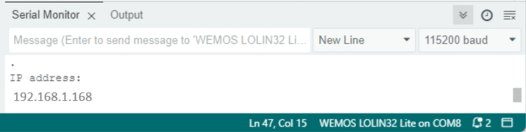
You will see a different IP address; the one assigned to your ESP32/ESP8266 board. Copy that address into the search bar of your browser. You should see the web page that the web server on your ESP32/ESP8266 creates:
Now, you can press the buttons to switch your Aircon of from a Webpage.
To summarize, this is how the overall system works. The ESP8266/ESP32 runs a webserver that is served to a Web browser. Web browser and Web server communicate via Wi-Fi through your Wi-Fi router. The ESP8266/ESP32 controls the Aircon via Infrared signals (IR) that mimic the commands your remote control would send. This also means that you can still use your remote.
Note, that the webpage is fairly safe, since it can only be accessed within your local Wi-Fi network. It is not publicly accessible from the internet! If you want that, it will require more work and safety measures, since it is risky to open up your Wi-Fi network to the internet!
Otherwise that’s it!
Conclusión
In this blog post, we learned how to control an air conditioner using infrared (IR) signals and an ESP32/ESP8266 microcontroller. By following the step-by-step guide provided, you can automate your cooling system and enjoy the convenience of remote control.
The code in this tutorial is just a beginning. There is so much more you can do! Starting with controlling more function of your Aircon, you could add additional sensors (motion, temperature, humidity) to control your Aircon automatically depending on environmental conditions. Pretty much any function that is missing from your Aircon you build yourself.
Have fun!
Frequently Asked Questions
Here are some frequently asked questions about controlling an air conditioner using infrared signals and an ESP32/ESP8266 microcontroller:
Q: Can I use any ESP32/ESP8266 board for this project?
A: Yes, you can use any ESP32/ESP8266 board for this project as long as it has the necessary GPIO pins to connect the IR diode and has a integrated Wi-Fi module.
Q: How does the ESP32/ESP8266 control the air conditioner using infrared signals?
A: The ESP32/ESP8266 is programmed to generate the necessary infrared signals that mimic the remote control signals of the air conditioner. By connecting the IR diode to the ESP32/ESP8266 and programming it accordingly, you can send specific infrared commands to the air conditioner, such as changing the temperature, mode, or fan speed.
Q: Can I control multiple air conditioners with a single ESP32/ESP8266?
A: Yes, you can control multiple air conditioners with a single ESP32/ESP8266 by using different IR codes for each air conditioner. By programming the ESP32/ESP8266 to send the appropriate IR codes for each air conditioner, you can control them individually or simultaneously.
Q: How do I increase the range of the IR transmitter?
A: You can use two (or more) IR transmitter that are controlled in parallel but connected to two different GPIO ports of your ESP8266 or ESP32. The better option is to power the IR Transmitter separately and to use a MOSFET (or transistor) to control it. If that is still not enough then you can again connect a second IR Diode and control both through the MOSFET. You would still need only one GPIO output. Here is an example schematic:
These are some of the frequently asked questions regarding controlling an air conditioner using infrared signals and an ESP32/ESP8266 microcontroller. If you have any more questions, feel free to ask in the comments section below.
Links
Here a collection of links to similar projects involving the control of ESP32 or ESP8266 microcontrollers over Wi-Fi using a web server.
- ESP32_HTTPS_Server – Arduino Reference
- ESP32 Web Server – Arduino IDE
- ESP32 – Web Server
- ESP32 Relay Module – Control AC Appliances
- In-depth: Create A Simple ESP32 Web Server In Arduino IDE
- SimpleWiFiServer Example
Stefan is a professional software developer and researcher. He has worked in robotics, bioinformatics, image/audio processing and education at Siemens, IBM and Google. He specializes in AI and machine learning and has a keen interest in DIY projects involving Arduino and 3D printing.
dela
Thursday 18th of April 2024
hai saya izin bertanya, saya menggunakan ac panasonic untuk model nya tertera dalam github ,yang digunakan program yang mananya ya ka?
Stefan Maetschke
Thursday 18th of April 2024
Hi, you would have to change the following constant to Panasonic: ac.next.protocol = decode_type_t::PANASONIC;
The constant definitions can be found here: https://github.com/UNUMobile/wf8266r/blob/master/Sample/WF8266Home/IRremoteESP8266.h
AlvinTan
Monday 19th of February 2024
Hola,
I found about your website is very useful for my current project which is using esp32 to control Panasonic aircon.
However I notice an alert mentioning
“Note that as of January 2024 the IRRemoteESP8266 library used to generate the IR signals for controlling an Aircon does not compile for the ESP32 and Arduino 3.0.0. I tried, but could not get it working. However, once the library is fixed, the code in this article should work for the ESP32 again.”
So I would like to seek clarify if the code works for esp32? If not, when can I expect fixture updates. Really appreciate if you could advise. Looking forward to your reply
AlvinTan
Friday 23rd of February 2024
@Stefan Maetschke,
Thanks. Will try your recommendations
Stefan Maetschke
Monday 19th of February 2024
Hi, I am not a maintainer or contributor to the IRRemoteESP8266 library, so I do not know what is on their roadmap and when a fix will be out. There seem to be aware of the issue, though. As of 20 Feb 2024, I still couldn't compile. Alternatively, you could try a different IDE, e.g. ESP-IDF or PlatformIO.