In this article, you will learn how to control a fan with an Arduino Uno. We will look at the different types of fans and methods to control them. By the end of this post, you will have a solid understanding of how to control a fan and be equipped with the knowledge to create your own fan control system.
So, let’s get started!
Required Parts
Below you will find the parts required for this project. I assume you already have a fan you want to control but you will find links to different types of fans in the next section as well.
We are going to use a 2N7000 MOSFET for some of the circuits in this blog. I provided a link to a kit with various transistors and MOSFETS, which is handy to have. You can also buy the 2N7000 MOSFET only but they typically come in packages of a 100pcs, which is probably more than you need.
If you want to control fans or devices that draw more current than 200mA, small MOSFETS like the 2N7000 will be not sufficient. You will need power MOSFETs, which can go up to 100A!

Arduino Uno

Dupont Wire Set

Tablero de pruebas

USB Cable for Arduino UNO
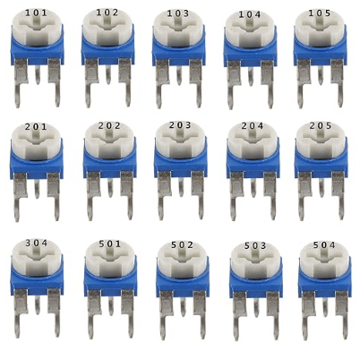
Trimmer Kit

Resistor & LED kit
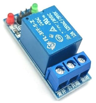
Relay Module

Transistor Kit
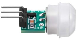
Motion Sensor
Temperature Sensor
Makerguides.com is a participant in the Amazon Services LLC Associates Program, an affiliate advertising program designed to provide a means for sites to earn advertising fees by advertising and linking to products on Amazon.com. As an Amazon Associate we earn from qualifying purchases.
Types of Fans
In this section we quickly have a look at the different types of fan you usually want to control with an Arduino.
AC versus DC Fans
When it comes to controlling a fan using Arduino, one of the key considerations is whether the fan operates on AC (alternating current) or DC (direct current). Understanding the difference between the two is crucial for selecting the appropriate fan and ensuring compatibility with your Arduino setup.
AC Fans
AC fans are designed to operate on the standard household electrical supply of 110V or 220V, for instance. You often see them as ceiling fans or in appliances like air conditioners. But you can also get small desk AC fans. AC fans typically run at fixed speeds. Below you can see a picture of a typical AC fan:
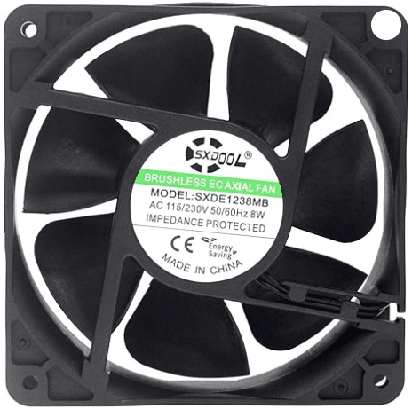
Note that you usually cannot tell from the looks of a fan if it is an AC or DV fan or which voltage it needs. You will have to check label (see above) that provides this information
To control an AC fan using Arduino, you typically will use a Relay or a Thyristor. Relays or Thyristors act as controllable switches that can handle the high voltage and current of an AC fan. Note, when dealing with high voltages be very careful!
DC Fans
DC fans, in contrast to AC fans, operate on direct current. They are commonly used in electronic devices such as computers, laptops, and for other small cooling systems. The typically run on 6V or 12V and can be easily controlled using an Arduino.
DC fans come in different configurations, such as 2-wire, 3-wire, and 4-wire variants. Let’s have a closer look at these variants in the next sections.
2-Wire DC Fan
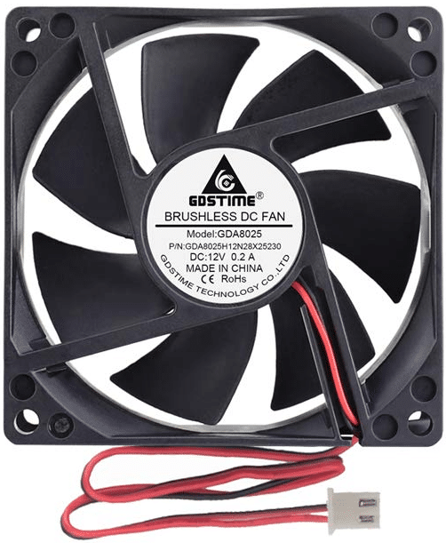
2-wire DC fans are the simplest type of DC fans. They have two wires – one red wire for power (VCC) and one black wire for ground (GND). These fans natively run at a fixed speed but the speed can be changed via Pulse Width Modulation (PWM). I will show you several examples how this is done. Below is a picture of a typical 12V DC fan. Note the two wires for power and ground.
3-Wire DC Fan
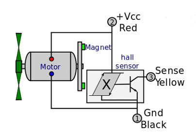
3-wire DC fans have the usual two wires for power and ground (red and black) and an additional wire (typically yellow) called the tachometer (TACH) wire. This wire provides a pulse signal that indicates the fan’s rotational speed. By reading this signal, you can monitor the fan speed in your Arduino project.
The tachometer signal is generated by a Hall effect sensor or an optical sensor that detects the passing of specific markings or features on the fan’s rotor or motor. The output is a pulse, and the frequency of the pulses corresponds to the speed of the fan. Higher RPM results in a higher frequency of pulses, while lower RPM results in a lower frequency.
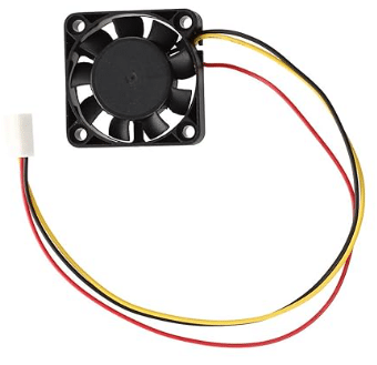
Many computer cooling fans are 3-wire fans but they are used in many other devices as well. Below a picture of a small 3-wire 12 DC fan for a 3D printer:
4-Wire DC Fan
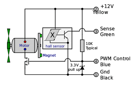
A 4-wire DC fan, is another type of fan typically used as cooling fan in computers. It is an extension of the 3-wire fan and has a fourth wire to control the fan speed. As with the 2-wire and 3-wire fans, the positive power supply wire is usually red and the ground wire is black. The tachometer (tacho) signal wire is yellow. The additional speed control wire is typically blue.
Fan speed is regulated by sending a PWM (Pulse Width Modulation) signal on the speed control wire, which is connected to a MOSFET that controls the motor. For more details have a look at the following circuit diagram.
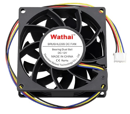
Below a picture of a typical 12V 4-wire DC fan used as a computer cooling fan:
In summary, 2 and 3-wire fans typically run at constant speed. 3-wire fans provide a tachometer signal to monitor to the fan speed. And 4-wire fans typically run at variable speed, controlled via a PWM signal on the fourth wire but also allow to monitor fan speed via the third wire.
Note that both, the tachometer and the speed control wire are using pulses as signals. But the tachometer signal is an output, while the speed control is an input. Also speed is controlled via a Pulse Width Modulation that has a variable duty cycle, while the tachometer signal has a constant 50% duty cycle but the frequency changes in relation to he speed.
In the following sections we will look at various methods to control a fan.
Example 1: Switch Fan with Relay
We start with the simplest possible way to control a fan. We connect one of the common relay modules to an Arduino and use it switch a fan on or off.
Note that you usually cannot connect a fan directly to one of the output pins of an Arduino. The output current on the GPIO pins of an Arduino is limited to 20mA (40mA short term). Apart from very small fans almost all fans will consume more power than that and also will require higher voltages than the 5V the GPIO pins deliver.
Breadboard Wiring
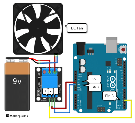
Connecting a fan via a relay to an Arduino is very simple. Have a look at the wiring diagram below.
Connecting the Relay to the Arduino
First connect the GND of the Arduino to the pin marked (-) or GND of the relay (blue wire). Then connect the 5V output of the Arduino to the positive power pin (+) of the relay (red wire). Next, we connect the signal wire(yellow) from pin 3 to the pin marked (S) on the relay module. This wire controls the relay, which in turn switches the fan on or off.
Connecting the Power Supply
Next we connect the Fan to the power supply. You will need a power supply or a battery that matches the power requirements of the fan. So, if you have a 12V, 180mA fan you will need a power supply or battery with 12V that can provide a current of at least 180mA. In short, your battery voltage must not be higher than the fan voltage but your battery current should be higher.
In the above example, I am using a 9V battery with 1000mAh to drive a 12V, 180mA fan. This works and is fine for testing but the fan will not move with full speed. For a real application, I would use a 12V battery or power supply.
Connecting the Fan
Connecting the fan is easy. We connect the blue/black wire of the fan to the minus (-) pole of the battery. The red wire goes to the switch terminals of the relay. One will will be marked GND (ground), one will be marked NO (normally open), one will be marked (NC) normally closed. Normally Open means, the switch is normally open and the fan will not run until the relay is activated. Connect the red wires of battery and fan to GND and NO. The order doesn’t matter.
Note, however, that many fans (specifically computer cooling fans) use brushless motors and have internal electronic that requires correct polarity. While you can change the direction a simple DC motor turns by swapping plus with minus, this generally does not work with brushless motors. They will run only in one direction with correct polarity. The advantages of brushless motors are that they are quiet, can run for a long time and don’t need a snubber diode.
You can use the circuit above also to switch AC fans but be careful! Definitely use a relay module instead of a plain relay, since relay modules typically have optocouplers to provide electrical isolation.
Code to control Fan with Relay
Switching the fan on or off using an Arduino is now very simple. You can see the code below, which periodically switches the fan on and off for 5 seconds.
// Control a relay to switch on/off a fan

const int relayPin = 3;

void setup() {
  pinMode(relayPin, OUTPUT);
}

void loop() {
  digitalWrite(relayPin, HIGH);
  delay(5000);
  digitalWrite(relayPin, LOW);
  delay(5000);
}
Let’s go through the code and understand how it works.
Constants and Variables
We start by defining the constant relayPin which specifies the pin to which the relay is connected. In this case, it is connected to pin 3.
const int relayPin = 2;
Setup function
En el setup() function, we set the mode of relayPin to OUTPUT. This is necessary because we will be writing to this pin to control the relay.
void setup() {
  pinMode(relayPin, OUTPUT);
}
Loop function
El loop() function is where the main logic of our code resides. In this function, we first set the relayPin to HIGH using the digitalWrite() function. This turns on the relay and switches the fan on. We then wait for 5000 milliseconds (5 seconds) using the delay() función.
void loop() {
  digitalWrite(relayPin, HIGH);
  delay(5000);
After the delay, we set the relayPin to LOW using the digitalWrite() function. This turns off the relay and switches the fan off. We again wait for 5000 milliseconds (5 seconds) using the delay() función.
  digitalWrite(relayPin, LOW);
  delay(5000);
This process of turning the fan on and off is repeated indefinitely in a loop, creating a continuous cycle of the fan being on for 5 seconds and then off for 5 seconds.
With the code and circuit above you can switch on or off a fan for given durations. You could now use the internal clock of the Arduino to switch on the fan at a specific time and let it run for a fixed duration, for instance.
In the next section, I will show you how to use a PIR module to switch on a fan when motion is detected.
Example 2: Switch Fan with Motion Detector
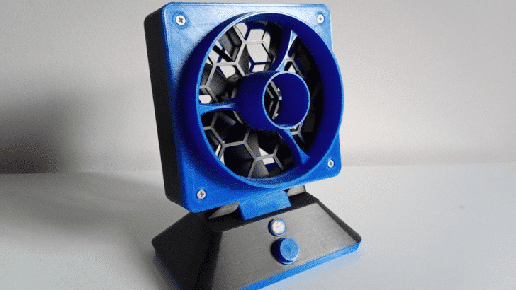
In many cases you want to run a fan only when motion is detected. For instance, the picture below shows a motion activated fan I built to remove soldering fumes. You can see the motion detector (PIR Sensor) in the base of the fan.
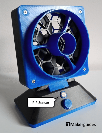
Circuit for Motion Activated Fan
The following circuit shows how you can build something similar. It uses a Passive Infrared Sensor (PIR) to detect motion that activates a relay, which in turn switches the fan on.
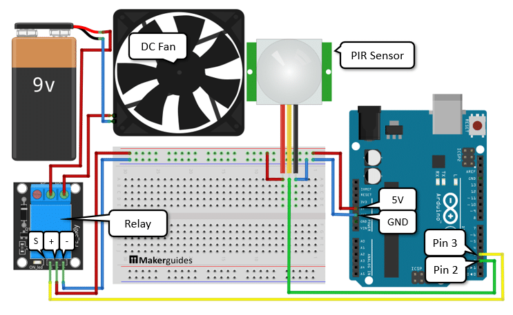
The circuit is essentially identical to the relay controlled fan circuit we have seen before. We just need to add the motion sensor. So, first connect battery, relay, fan and Arduino in the same way. Then we need to connect plus and minus of the PIR sensor to the positive and negative power rails of the breadboard (blue and red wires). Finally, we connect the signal output of the PIR Sensor to pin 2 of the Arduino (green wire).
Code for Motion Activated Fan
Below you can find the code for the motion activated fan. It polls (=reads) the motion sensor every 100ms and if motion is detected, switches the fan on for 10 seconds. Have a quick look first and then we discuss the details.
// Switch on fan for 10 seconds via relay
// if PIR sensor detects motion

const int motionPin = 3;
const int relayPin = 2;

void setup() {
  pinMode(motionPin, INPUT);
  pinMode(relayPin, OUTPUT);
}

void loop() {
  int motionState = digitalRead(motionPin);

  if (motionState == HIGH) {
    digitalWrite(relayPin, HIGH);
    delay(10000);  // 10 seconds
    digitalWrite(relayPin, LOW);
  }
  delay(100);
}
Constants and Variables
We start by defining the constants motionPin y relayPin which specify the pins to which the PIR sensor and relay are connected, respectively.
const int motionPin = 3;
const int relayPin = 2;
Setup function
En el setup() function, we set the mode for motionPin to INPUT y relayPin to OUTPUT since we are reading from the PIR sensor and writing to the relay.
void setup() {
  pinMode(motionPin, INPUT);
  pinMode(relayPin, OUTPUT);
}
Loop function
En el loop() function, we first read the state of the PIR sensor using digitalRead(motionPin) and store it in the variable motionState.
void loop() {
  int motionState = digitalRead(motionPin);
If the motionState is HIGH, indicating motion is detected, we switch on the fan by setting the relayPin to HIGH using digitalWrite(relayPin, HIGH). We then wait for 10 seconds using delay(10000) to keep the fan on. After that, we switch off the fan by setting the relayPin to LOW using digitalWrite(relayPin, LOW).
  if (motionState == HIGH) {
    digitalWrite(relayPin, HIGH);
    delay(10000);  // 10 seconds
    digitalWrite(relayPin, LOW);
  }
Finally, we add a small delay of 100ms using delay(100) to avoid reading the PIR sensor too frequently and to allow other tasks to be performed by the Arduino.
delay(100);
And that’s it. Now you have a motion activated fan!
Example 3: Control Fan Speed with PWM
In the examples above we have switched a fan on or off. But what if we want to control the speed of the fan? In this example we will learn how to do this.
Commonly we use Pulse Width Modulation (PWM) to control the power delivered to a device. PWM is a technique where the average value of a signal is adjusted by varying the duty cycle of a square wave. By changing the duty cycle, we can control the speed of the fan. See our tutorial on How use Arduino to control an LED with a Potentiometer for more details about PWM.
However, you cannot directly connect a fan to an Arduino and control it in this fashion, since a fan draws to much power. In the examples above we use a relay to get around this problem. But relays are too slow for PWM and wouldn’t endure for long due the mechanical stress a PWM signal would cause.
MOSFET
We therefore going to use a MOSFET. A MOSFET, or Metal-Oxide-Semiconductor Field-Effect Transistor, is a type of transistor that is widely used in electronic circuits. It is a three-terminal device (Drain, Gate, Source) that can amplify and switch electronic signals. The MOSFET operates by controlling the flow of current between its Source and Drain terminals using an electric field generated by a voltage applied to its Gate terminal. It is known for its high switching speed, low power consumption, and ability to handle high currents and voltages.
In this example, I will be using a 2N7000 MOSFET. See the circuit symbol and pinout of the 2N7000 below.
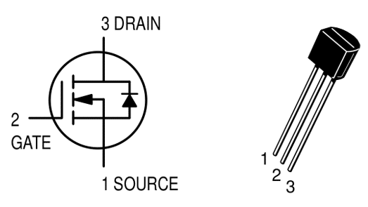
For more detail, have a look at the datasheet of the 2N7000:
The 2N7000 can switch up to 60V and 200mA continuously. That is sufficient for my small fan. You typically can find out the voltage and current requirements by looking at the label. The picture below shows the label of my fan that runs on 12V and draws a current of 0.18A = 180mA. The 2N7000 MOSFET is therefore fine to control my fan.

If you have a bigger fan that draws more current you will need a bigger MOSFET. There are many different types and some of them can switch 100A and more! Just look for one with a voltage (VDSS) and current (ID) rating above what your fan needs. The Transistor Kit proposed under required parts has a good selection.
As a rule of thumb go for about 2x higher to be on the safe side and to avoid the need for cooling. For smaller fans, like the one I am using here, you don’t need that much of a safety buffer.
Circuit to Control Fan Speed
In this section I show you and explain the circuit need to control a fan with a MOSFET. It is very simple. Have a look:
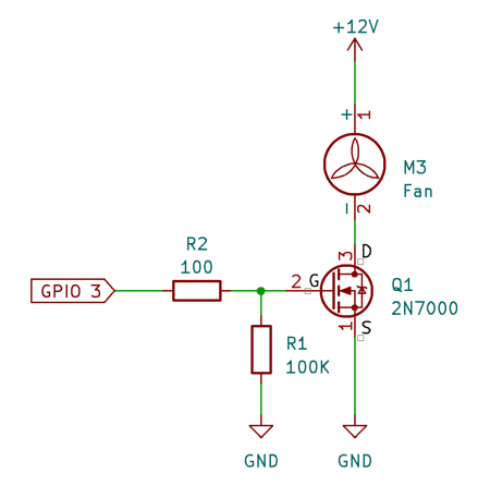
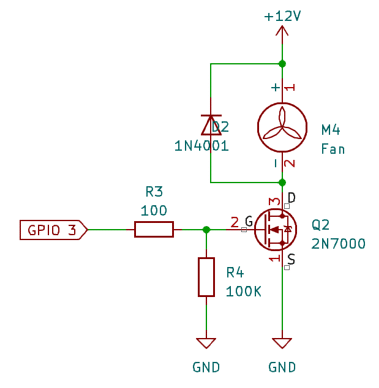
We connect one of the PWM outputs of the Arduino, here GPIO 3, to the Gate (G) pin of the 2N7000 MOSFET. The 100Ω resistor (R2) is just a the current limiting resistor for safety reasons. You could leave that one out. The second resistor (R1) with 100KΩ, is a pulldown resistor that ensures that the MOSFET switches off, when the gate is not connected.
The fan is connected to +12V and the Drain (D) of the MOSFET, while the Source (S) is connected to Ground (GND). If the Gate of the MOSFET receives an PWM impulse it opens, and current can flow from Drain to Source, which allows the fan to receive power. Remember, that brushless fans have polarity. So, if the fan does not spin, check for correct polarity and also correct orientation of the MOSFET.
If you use a standard DC motor or a non-brushless Fan, you should add a Flyback Diode in parallel to the motor to supress the voltage spikes an inductive load such a motor or solenoid causes. Below a picture of the circuit but with an additional Flyback Diode:
Code to Control Fan Speed
An here is the code example for controlling the fan. It will switch off the fan for 3 seconds, then let it spin for 3 seconds with medium speed, and then for another 3 seconds with full speed.
// Code to control Fan speed via PWM

int fanPin = 3;

void setup() {
  pinMode(fanPin, OUTPUT);
}

void loop() {
  // Fan off
  analogWrite(fanPin, 0);
  delay(3000);

  // Medium speed
  analogWrite(fanPin, 150);
  delay(3000);

  // Max speed
  analogWrite(fanPin, 255);
  delay(3000);
}
Let’s dive into the code and understand how it works.
Constants and Variables
In this code, we have a single variable called fanPin. This variable is used to store the pin number to which the fan is connected. In this case, the fan is connected to pin 3. Note that you must use a PWM pin! PWM pins on the Arduino Uno are identified with a “~” sign, such as ~3, ~5, ~6, ~9, ~10 and ~11.
int fanPin = 3;
Setup function
En el setup() function, we set the mode of the fanPin to OUTPUT. This is necessary because we will be writing to this pin to control the fan speed.
void setup() {
  pinMode(fanPin, OUTPUT);
}
Loop function
En el loop() function, we control the fan speed using PWM. We have three different speed levels: off, medium, and maximum.
First, we turn off the fan by setting the PWM value to 0 using analogWrite(fanPin, 0). We then wait for 3 seconds using delay(3000).
// Fan off
analogWrite(fanPin, 0);
delay(3000);
Next, we set the fan speed to a medium level by setting the PWM value to 150 using analogWrite(fanPin, 150). Again, we wait for 3 seconds.
// Medium speed
analogWrite(fanPin, 150);
delay(3000);
Finally, we set the fan speed to the maximum level by setting the PWM value to 255 using analogWrite(fanPin, 255). We wait for another 3 seconds before repeating the loop.
// Max speed
analogWrite(fanPin, 255);
delay(3000);
This loop will continue indefinitely, cycling through the different fan speeds.
With this code and circuit, you can control the speed of pretty much any fan. It will work for brushless and brushed fans, 2 and 3 wire fans. If you have a 4-wire fan, which already has an internal control circuit for speed, you won’t need the MOSFET circuit shown above, but can provide the PWM signal directly.
Example 3: Temperature Controlled Fan
A very common use case it to regulate the fan speed based on ambient temperature. I’ll show you how that is done in this example.
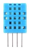
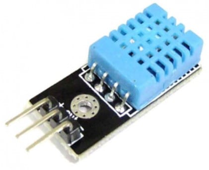
First we will need a sensor to measure the temperature. There are many different kinds of temperature sensors and it doesn’t matter too much, which one. Here I will use the DHT11 temperature & humidity sensor. You can get them as modules or as the plain sensor itself. Both are fine and work the same way.
If you need more details about the DHT11 and its cousin the DHT22 have a look at our tutorial: DHT11/DHT22 Sensor with Arduino Tutorial. Instead of the DHT11 you could also use the TMP36, the LM35 or the DS18B20. These are other suitable temperature sensors but you will need to adjust the circuit and code a bit if you use them.
Circuit for Temperature Controlled Fan
The circuit to control the fan speed with a DHT11 is shown below. You can swap the DHT11 with a DHT21 or DHT22 without having to change the circuit.
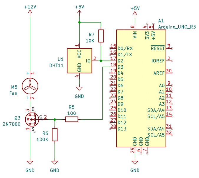
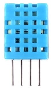
As you can see we are using the same MOSFET based circuit to control the fan via PWM from pin 3 of the Arduino. We just add the DHT11 and connect its IO pin to pin 2 of the Arduino. For power, connect the VCC pin to 5V and the GND pin to GND. The following picture shows the pinout of the DHT11
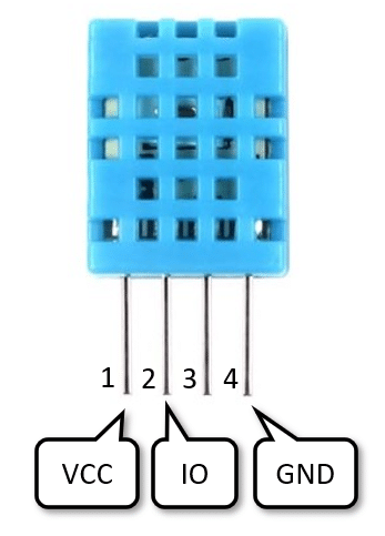
Note that pin3 is not used. That is why the DHT modules have only three pins, while the sensor has 4 pins.
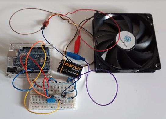
Below a picture of a the completed circuit using a small fan, a 9V battery and a breadboard.
Code for Temperature Controlled Fan
The following code shows you how to use PWM (Pulse Width Modulation) and the temperature readings from the DHT11 sensor to adjust the fan speed.
// Control fan speed using PWM based
// on temperature reading from DHT11 sensor

#include "Adafruit_Sensor.h"
#include "DHT.h"

const int tempPin = 2;
const int fanPin = 3;

// Sensor types: DHT11, DHT22, DHT21
DHT dht = DHT(tempPin, DHT11);

void setup() {
  dht.begin();
  pinMode(fanPin , OUTPUT);
}

void loop() {
  float temp = dht.readTemperature(); // Celsius
  if (isnan(temp)) return;

  int fanSpeed = map(temp, 20, 40, 0, 255);
  fanSpeed = constrain(fanSpeed, 0, 255);
  analogWrite(fanPin, fanSpeed);

  delay(5000);
}
Let’s break down the code and understand how it works.
Libraries
The DHT11 uses a comparatively complex communication protocol (see datasheet). You could implement that yourself but it is easier to use a library. There are several Arduino libraries for the DHT11 sensor. Here we use one from Adafruit.
#include "Adafruit_Sensor.h"
#include "DHT.h"
You will need to install the “Adafruit_Sensor.h” base library and the their “DHT.h” library. Have a look at our tutorial: DHT11/DHT22 Sensor with Arduino Tutorial, if you need more details.
Constants and Variables
We start by defining two constants: tempPin y fanPin. tempPin represents the pin number to which the DHT11 sensor is connected, and fanPin represents the pin number to which the fan is connected.
const int tempPin = 2;
const int fanPin = 3;
Next, we create an instance of the DHT library and initialize it with the tempPin and the sensor type, which in this case is DHT11. If you want to use a DHT21 or DHT22 instead of a DHT11, just change the constant name.
// Sensor types: DHT11, DHT22, DHT21
DHT dht = DHT(tempPin, DHT11);
Setup function
En el setup() function, we initialize the DHT sensor using the dht.begin() function. We also set the fanPin as an output pin using the pinMode() función.
void setup() {
  dht.begin();
  pinMode(fanPin , OUTPUT);
}
Loop function
En el loop() function, we first read the temperature in Celsius from the DHT sensor using the dht.readTemperature() function. If you want to use Fahrenheit instead of Celsius just call dht.readTemperature(true).
If the sensor cannot read the temperature it will return Not-a-Number (NaN). In this case, we exit the function using the return statement.
Otherwise, we map the temperature value from the range of 20 to 40 degrees Celsius to a range of 0 to 255. This will be used to control the fan speed. That means at 20 degrees Celsius the fan speed is still 0 but above 20 degrees Celsius the fan starts to spin very slowly until it reaches is maximum speed (255) at 40 degrees Celsius.
For many applications you may want to change this behavior and start the fan with a medium speed, when some temperature threshold is reached, since very slow speeds of the fan have almost no cooling effect and the fan might not even start turning for small PWM values.
float temp = dht.readTemperature();
if (isnan(temp)) return;

int fanSpeed = map(temp, 20, 40, 0, 255);
Tenga en cuenta que el map() function actually does not guarantee that the fanSpeed will be in the permitted value range [0..255]. For instance, for temperatures smaller than 20 degrees Celsius it will return negative values!
We don’t want that and therefore use the constrain() function to constrain the fan speed value to be within the range of 0 to 255.
fanSpeed = constrain(fanSpeed, 0, 255);
Finally, we use the analogWrite() function to set the fan speed by providing the fanPin and the fan speed value. As mentioned before, for small PWM values (fanSpeed < 10) the fan might not even start turning. Try it with your fan and find a minimum value that suits your application. Maybe you want to start the fan with a speed of 100 when the temperature exceeds 20 degrees Celsius.
analogWrite(fanPin, fanSpeed);
Finally, we add a delay of 5 seconds using the delay() function before the loop repeats. So, we essentially sample the ambient temperature every 5 seconds and adjust the fan speed accordingly.
delay(5000);
And that’s a temperature controlled fan for you!
Conclusions
In this blog post, we have learned how to control a fan using Arduino. We started by discussing the required parts for this project, including an Arduino board, a fan, and various electronic components like relays, MOSFETs and temperature sensors.
After that we explored the different types of fans available in the market, such as AC and DC fans. We discussed the advantages and disadvantages of each type and how they can be used in different scenarios.
Moving on, we delved into the specifics of controlling DC fans, particularly the 2, 3, and 4-wire configurations. We explained how each wire is used for different purposes, such as power, ground, tachometer signal, and PWM control.
To provide practical examples, we showcased various methods of controlling fans using Arduino. We demonstrated how to switch an AC or DC fan using a relay.
Furthermore, we explored more advanced techniques like controlling fan speed using PWM with a MOSFET. We explained how pulse width modulation can be used to vary the speed of the fan, allowing for precise control based on the desired cooling requirements.
Lastly, we presented an example of controlling fan speed based on ambient temperature using a MOSFET. This application can be handy in environments where temperature regulation is crucial, such as in electronic enclosures or server rooms.
We hope this blog post has provided you with valuable insights and inspiration for your fan control projects. Feel free to experiment and explore further possibilities with Arduino and fans!
Frequently Asked Questions
Here are some frequently asked questions about controlling a fan using Arduino:
Q: What is the difference between AC and DC fans?
A: The main difference between AC and DC fans is the type of power they require. AC fans are designed to run on the mains electricity supply, which is an alternating current. DC fans, on the other hand, are designed to run on a direct current power source, such as a battery or power supply.
Q: How do I switch a fan using a relay?
A: To switch a fan using a relay, you need to connect the relay module to the Arduino. The Arduino can then control the relay, which in turn switches the fan on or off. You will need to connect the relay’s input pin to one of the Arduino’s digital pins, and the relay’s output pins to the fan’s power supply.
Q: How can I control the speed of a fan using Arduino?
A: To control the speed of a fan using Arduino, you can use a MOSFET module. By connecting the MOSFET module to the Arduino, you can vary the voltage supplied to the fan, thus controlling its speed. This can be achieved using pulse width modulation (PWM) signals generated by the Arduino.
Q: Can I read the speed signal from a fan using Arduino?
A: Yes, you can read the speed signal from a fan using Arduino. Some fans have a tachometer output that provides a pulse signal proportional to the fan’s speed. By connecting this signal to one of the Arduino’s digital pins, you can measure the fan’s speed. If the fan has no speed wire then you can build your own speed monitor. See our tutorial Build Arduino Tachometer Using A3144 Hall Effect Sensor.
Q: Can I control the fan speed based on ambient temperature?
A: Yes, you can control the fan speed based on ambient temperature using Arduino. By connecting a temperature sensor to the Arduino, you can measure the ambient temperature and adjust the fan speed accordingly.
Q: Can I control the fan speed based on ambient light?
A: Yes, you can control the fan speed based on ambient light. By connecting a light sensor in a voltage divider arrangement to the Arduino, you can measure the ambient light and adjust the fan speed accordingly. Below is the basic circuit to measure light.
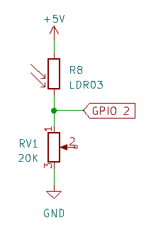
For more details have a look at our tutorial How to detect light using an Arduino.
Q: Can I use a DS18B20 temperature sensor instead of a DHT11?
Yes, you can but you will have to change the code. Here a short example on how to read temperature data from the DS18B20:
// https://github.com/matmunk/DS18B20
#include "DS18B20.h"

const int tempPin = 2;
DS18B20 ds(tempPin);

void setup() {
  Serial.begin(9600);
}

void loop() {
  while (ds.selectNext()) {
    float temp = ds.getTempC();
	...
    delay(1000);
  }
}
Q: Can I control the direction of a fan using Arduino?
It depends. Brushless fans and AC fans usually spin only in one direction. Changing polarity to change the direction will not work with these fans. On the other hand, if the fan is using a simple, brushed DC motor, then you could control the direction. You would need a H-bridge or a motor driver board to do that.
Q: Can I control multiple fans using Arduino?
Yes, you can control multiple fans using Arduino by utilizing appropriate electronic components like relays or MOSFETs. Each fan would require its own control circuit, but they can all be controlled by a single Arduino board.
These are just a few of the frequently asked questions about controlling a fan using Arduino. If you have any more questions, feel free to ask in the comments section below.

I am Puneeth. I love tinkering with open-source projects, Arduino, ESP32, Pi and more. I have worked with many different Arduino boards and currently I am exploring, Arduino powered LoRa, Power line communication and IoT.
Mathieu Girard
Sunday 3rd of December 2023
Hi!
I'm working on a project right now and I basically want my fan to be powered by the amount of light that is going through a LDR. At first, I thought about only swapping your LM35 in your picture for the project 2 for a LDR and change a little bit the code that you provide but I seem to go nowhere... My question is: how would you change the circuit and the code for it to work with a LDR instead of a LM35?
Mathieu Girard
Tuesday 5th of December 2023
https://www.pinterest.ca/pin/815996026260409977/ https://www.pinterest.ca/pin/815996026260409984/
Here is two picture of my circuit. It doesn't work very well and I don't seem to know why... The resistors are 1kohm and the capacitor is 1uF, I tried with different values and it doesn't help at all
Mathieu Girard
Tuesday 5th of December 2023
If I want to remove all of the diodes do I need to change the circuit?
Mathieu Girard
Tuesday 5th of December 2023
Alright I'll try that thanks!
Stefan Maetschke
Monday 4th of December 2023
Hi, You would have to replace the LM35 by an LDR in a voltage divider configuration (see here: https://www.makerguides.com/arduino-uno-and-light-sensor-project/). The code can largely unchanged. Just replace readTemp() by readLight() and change the scaling factors and thresholds depending on your needs.