In this tutorial, you will learn how to implement a web server on the ESP32 microcontroller to control it wirelessly over Wi-Fi. This allows you use a the web server to switch the built-in LED from a web page.
The ESP32 is a powerful microcontroller that offers built-in Wi-Fi capabilities, making it an ideal choice for projects that require wireless communication. By setting up a web server on the ESP32, we can create a user interface accessible from any computer or phone connected to the same Wi-Fi network.
Controlling devices remotely through a web server opens up a wide range of possibilities for home automation, IoT projects, and even robotics. Imagine being able to turn on or off lights, appliances, or a robot from your smartphone or computer.
Comencemos.
Required Parts
Below you will find the components required to build the project. For this project, I am using an older ESP32 board, which has been deprecated but you can still get it for a very low price. That’s the one listed below. There is a successor model with improved specs, which you can find here.
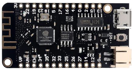
ESP32 lite
USB Data Cable
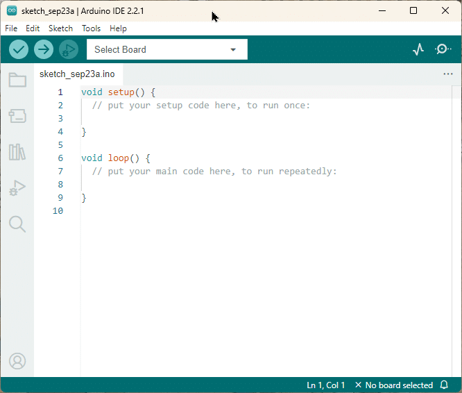
Arduino IDE
Makerguides.com is a participant in the Amazon Services LLC Associates Program, an affiliate advertising program designed to provide a means for sites to earn advertising fees by advertising and linking to products on Amazon.com. As an Amazon Associate we earn from qualifying purchases.
I like the ESP32 lite because of the low price and the battery connector with recharging capability. But pretty much any other ESP32 board should work with this project. Since we will use the built-in LED of the ESP32, you won’t need any other hardware components.
In the next section, we will have a quick look at the basics of Wi-Fi communication.
How Wi-Fi works
Wi-Fi, short for Wireless Fidelity, is a technology that allows devices to connect to the internet or communicate with each other wirelessly.
Understanding the Basics
Wi-Fi uses radio frequency signals to transmit and receive data between devices. These radio waves are transmitted through the air and can travel through walls and other obstacles, allowing for wireless communication.
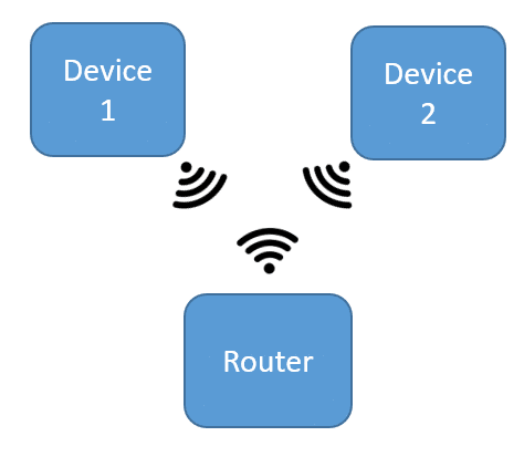
To establish a Wi-Fi connection, you need two main components: a Wi-Fi-enabled device (such as an ESP32) and a Wi-Fi router (see picture above). The router acts as a central hub that allows your devices to communicate with each other on the network.
Note that the router can also connect your device to the internet but we are no going to do this, in this project.
The Role of SSIDs and Passwords
When you connect to a Wi-Fi network, you are prompted to enter the network’s SSID (Service Set Identifier) and password. The SSID is a unique name that identifies the Wi-Fi network (for instance “my_home_wifi”), while the password ensures secure access to the network. So nobody without the password will be able to access the ESP32 webserver we are going to implement.
Once you enter the correct SSID and password, your device sends a connection request to the Wi-Fi router. The router then authenticates your device and assigns it an IP address, which serves as a unique identifier on the network.
IP Addresses and Communication
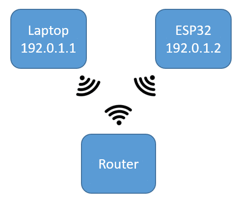
IP addresses play a crucial role in Wi-Fi communication. An IP address is a unique, numerical label, for instance 192.0.1.1 or 192.0.1.2, that is assigned to each device on a network. It allows devices to send and receive data to specific devices.
When you connect your ESP32 to a Wi-Fi network, it is assigned an IP address by the router. This IP address allows other devices on the network to communicate with the ESP32. For example, when you access a web page hosted on the ESP32, your device sends a request to the ESP32’s IP address, and the ESP32 responds by serving the requested web page.
Wi-Fi Standards and Frequencies
Wi-Fi technology has different standards and frequencies. The most common Wi-Fi standards are 802.11b, 802.11g, 802.11n, and 802.11ac, each offering different speeds and capabilities.
Wi-Fi operates on two main frequency bands: 2.4 GHz and 5 GHz. The 2.4 GHz band has a longer range but can be more susceptible to interference from other devices, such as microwaves and cordless phones. The 5 GHz band provides faster speeds but has a shorter range.
Current ESP32 Wi-Fi modules usually use the 802.11 b/g/n (802.11n up to 150 Mbps), 2.4 GHz standard.
In the next section, you will learn what a web server is and how it can be used to control an ESP32 wirelessly.
What is a Webserver?
A web server is a software application that runs on a computer and is responsible for serving web pages to clients/devices. It acts as a mediator between the client’s web browser and the requested web page. When a client/device sends a request for a web page, the web server processes the request and sends back the requested web page to the client.
In the context of controlling an ESP32 wirelessly over Wi-Fi, a web server allows us to create a user interface that can be accessed through a web browser running on a computer. This user interface can be used to send commands to the ESP32 via the router, such as turning on or off LEDs.
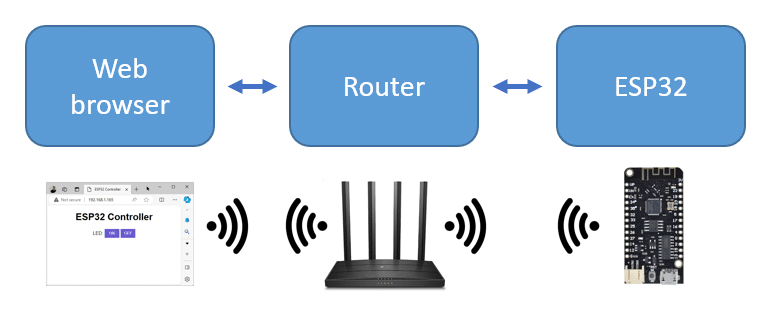
The web server on the ESP32 listens for incoming requests from clients, such as a web browser, and responds to those requests by sending back the appropriate web page or executing the requested action. In our case, we will be implementing a web server on the ESP32 that can receive commands from a web page and control the LEDs accordingly.
The web server typically sends a web page in HTML format and the next section will give you a very short introduction into HTML.
What is HTML?
HTML stands for HyperText Markup Language. It is the standard computer language used for creating web pages and applications. It uses a set of tags to define the elements and their properties within a web page.
HTML tags are enclosed in angle brackets (< >) and consist of an opening tag and a closing tag. The opening tag denotes the start of an element, while the closing tag signifies the end of the element. The content between the opening and closing tags represents the information associated with that element.
HTML tags can be used to define headings, paragraphs, lists, images, links, tables, forms, and much more. These tags allow you to structure and organize your content, making it easier for browsers to interpret and display the web page correctly.
Example of an HTML page
Here’s an example of the simple HTML web page we will be using to control our ESP32:
<!DOCTYPE html>
<html>
<head>
  <title>ESP32 Controller</title>
</head>
<body>
  <h1>ESP32 Controller</h1>
  <p>LED:
    <a href="/led/on"><button>ON</button></a>
    <a href="/led/off"><button>OFF</button></a>
  </p>
</body>
</html>
In the this example, we have an HTML document enclosed within the “html” tags. The “head” section contains meta-information about the web page, such as the title displayed in the browser’s title bar.
<head>
  <title>ESP32 Controller</title>
</head>
El “body“ section contains the visible content of the web page. Within the “body“ section, we see various other HTML tags. The “h1“ tag represents a heading, and the “p“ a paragraph. Within the paragraph we have two “a” tags that create hyperlinks. In this case, the hyperlinks are attached to two button that switch an LED on or off.
  <h1>ESP32 Controller</h1>
  <p>LED:
    <a href="/led/on"><button>ON</button></a>
    <a href="/led/off"><button>OFF</button></a>
  </p>
Displaying the webpage
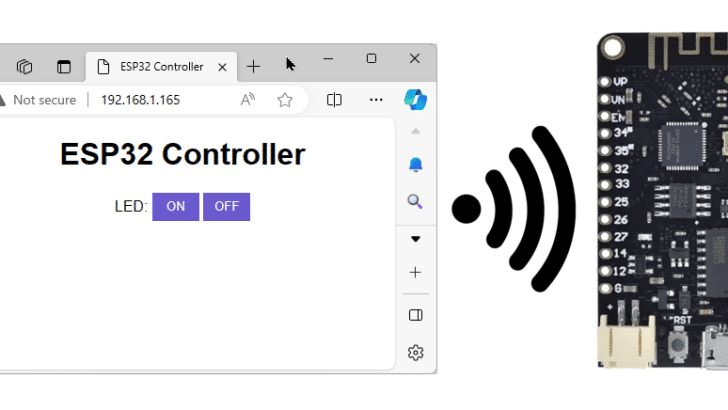
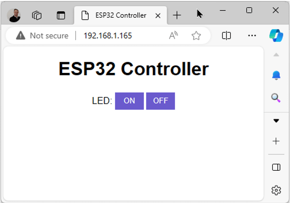
If you woudl write this HTML code to a file (e.g. test.html) and load it into your web browser you would see the following web page:
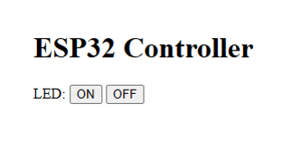
You would notice, when you click on the buttons nothing is happing. This is because, we are not running our web server yet, which will react to these buttons. But that is what we are going to implement in the next section.
Implementing the Webserver
The following code shows the implementation of a web server running on an ESP32 that allows you to switch on and off the built-in LED of the ESP32 via a button press on the web page. Have a quick look at the complete code first. I will explain the different parts of the code in the following sections.
// Switch built-in LED of ESP32 via web server.  Based on
// https://github.com/espressif/arduino-esp32/blob/master/libraries/WiFi/examples/SimpleWiFiServer/SimpleWiFiServer.ino

#include "WiFi.h"

const char* ssid = "*****";
const char* password = "*****";
const int ledPin = LED_BUILTIN;


const char* html = R""""(
HTTP/1.1 200 OK
Content-type:text/html

<!DOCTYPE html>
<html>
<head>
  <title>ESP32 Controller</title>
  <style>
    body { text-align: center; font-family: Arial, sans-serif; }
    button { background-color: slateblue; color: white; border: none; width: 50px; height: 30px; }
    button:hover { background-color: darkslateblue; }
    button:active { background-color: mediumslateblue; }
  </style>
</head>
<body>
  <h1>ESP32 Controller</h1>
  <p>LED:
    <a href="/led/on"><button>ON</button></a>
    <a href="/led/off"><button>OFF</button></a>
  </p>
</body>
</html>
)"""";

WiFiServer server(80);

void setup() {
  Serial.begin(115200);
  pinMode(ledPin, OUTPUT);
  digitalWrite(ledPin, HIGH);

  delay(10);
  WiFi.begin(ssid, password);
  while (WiFi.status() != WL_CONNECTED) {
    delay(500);
    Serial.print(".");
  }
  Serial.println("");
  Serial.println("IP address: ");
  Serial.println(WiFi.localIP());

  server.begin();
}

void loop() {
  WiFiClient client = server.accept();
  if (client) {
    String currentLine = "";
    while (client.connected()) {
      if (client.available()) {
        char c = client.read();
        Serial.write(c);
        if (c == '\n') {
          if (currentLine.length() == 0) {
            client.println(html);
            break;
          } else {
            currentLine = "";
          }
        } else if (c != '\r') {
          currentLine += c;
        }

        // Execute commands
        if (currentLine.endsWith("GET /led/on")) {
          digitalWrite(ledPin, LOW);
        }
        if (currentLine.endsWith("GET /led/off")) {
          digitalWrite(ledPin, HIGH);
        }
      }
    }
    client.stop();
  }
}
Note that you need to have the ESP32 core installed to use this code within the Arduino IDE. We have the following tutorial on that, if you need help: How to Program ESP32 with Arduino IDE.
Libraries and Constants
To begin with, we include the necessary library for Wi-Fi communication. It is part of the ESP32 core and does not require any special installation.
#include "WiFi.h"
Next, we define the SSID and password for our Wi-Fi network. You have to replace these ones with the login credentials of your Wi-Fi network. The SSID is the name of your home Wi-Fi, e.g. “my_home_wifi” and the password is the one you usually use to connect to this network (with your phone or computer).
const char* ssid = "*****";
const char* password = "*****";
We also define the pin number for the built-in LED on the ESP32. You could easily connect an external LED, or other devices such as relays. Just add the relevant pin definitions here and connect the hardware.
const int ledPin = LED_BUILTIN;
HTML for web page
Next, we write the HTML code that will be sent to the web browser. This HTML code includes a title, some CSS styling, and buttons to control the LED.
const char* html = R""""(
HTTP/1.1 200 OK
Content-type:text/html

<!DOCTYPE html>
<html>
<head>
  <title>ESP32 Controller</title>
  <style>
    body { text-align: center; font-family: Arial, sans-serif; }
    button { background-color: slateblue; color: white; border: none; width: 50px; height: 30px; }
    button:hover { background-color: darkslateblue; }
    button:active { background-color: mediumslateblue; }
  </style>
</head>
<body>
  <h1>ESP32 Controller</h1>
  <p>LED:
    <a href="/led/on"><button>ON</button></a>
    <a href="/led/off"><button>OFF</button></a>
  </p>
</body>
</html>
)"""";
It is essentially the same HTML code I showed you in the section “What is HTML?”. Just with some additional CSS styling to make the web page look nicer. Below is a picture of what you will see in a browser (here the Edge browser):
After that, we create a Wi-Fi server object on port 80, in the following line. Port 80 is the port commonly used to serve web pages. You can read more about ports here.
WiFiServer server(80);
Setup function
In the setup function, we initialize the serial communication for debugging purposes, set the LED pin as an output, and turn the LED on.
  Serial.begin(115200);
  pinMode(ledPin, OUTPUT);
  digitalWrite(ledPin, HIGH);
We then connect to the Wi-Fi network using the provided SSID and password and wait for a successful connection. Check the Serial Monitor and if you see only “dots” appearing, something is wrong. Make sure you have the correct SSID and password.
  delay(10);
  WiFi.begin(ssid, password);
  while (WiFi.status() != WL_CONNECTED) {
    delay(500);
    Serial.print(".");
  }
  Serial.println("");
  Serial.print("IP address: ");
  Serial.println(WiFi.localIP());
If we could connect to the Wi-Fi network, we print out the IP address. Make a copy of it, since you will need it later for the web browser.
Once the connection to the Wi-Fi is established, we start the Wi-Fi server via
server.begin();
Loop function
In the loop function, we check if there is a client connected to the server. The client will be the web browser. If there is, we read the incoming data from the client and process it.
The following code is largely based on the SimpleWiFiServer example provided by the WiFi library. If you need more detailed information or application have a look there.
void loop() {
  WiFiClient client = server.accept();
  if (client) {
    String currentLine = "";
    while (client.connected()) {
      if (client.available()) {
        char c = client.read();
        Serial.write(c);
        if (c == '\n') {
          if (currentLine.length() == 0) {
            client.println(html);
            break;
          } else {
            currentLine = "";
          }
        } else if (c != '\r') {
          currentLine += c;
        }

        // Execute commands
        if (currentLine.endsWith("GET /led/on")) {
          digitalWrite(ledPin, LOW);
        }
        if (currentLine.endsWith("GET /led/off")) {
          digitalWrite(ledPin, HIGH);
        }
      }
    }
    client.stop();
  }
}
Inside the loop, we read each character from the client and append it to the current line. When we encounter a newline character, we check if the current line is empty. If it is, we send the HTML code to the client. If not, we clear the current line.
The most important part is, where we check the contents of the current line. If we find that the current line ends with “/led/on” or “/led/off”, we turn the LED on or off accordingly by calling digitalWrite for the ledPin.
Note that the logic for the built-in LED of the ESP32 lite (and some other boards) is inverted. We set the ledPin to LOW, if we want to switch the led “on” and vice versa. For external LEDs, we need to set the ledPin to HIGH to switch the LED on.
        if (currentLine.endsWith("GET /led/on")) {
          digitalWrite(ledPin, LOW);
        }
        if (currentLine.endsWith("GET /led/off")) {
          digitalWrite(ledPin, HIGH);
        }
In case, you want add additional commands, this is the place to do it! For instance, we could switch a relay on or off, assuming that a relay is connected to relayPin, be adding the following lines:
        if (currentLine.endsWith("GET /relay/on")) {
          digitalWrite(relayPin, LOW);
        }
        if (currentLine.endsWith("GET /relay/off")) {
          digitalWrite(relayPin, HIGH);
        }
Just remember to add a relayPin constant and additional buttons to the web page as well:
  <p>Relay:
    <a href="/relay/on"><button>ON</button></a>
    <a href="/relay/off"><button>OFF</button></a>
  </p>
Note that the commands “led/on”, “led/off”, … that are used in the web page and in the code that executes the commands have to match!
If you press a button, you will see the command appear as a link after the IP address in your web browser:
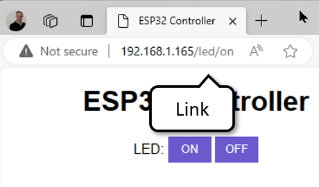
You can use these links to action commands instead of pressing buttons as well. And you can also use these links in other webpages, e.g. an IoT home server web site that runs on your Wi-Fi network.
Running the Web server
If you reset your ESP32 and open the Serial Monitor you should see a text that shows the IP address of your ESP32. In my case, for my ESP32 that is 192.168.1.165, for instance.
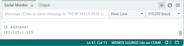
You will see a different IP address; the one assigned to your ESP32 board. Copy that address into the search bar of your browser. You should see the web page that the web server on your ESP32 creates:
Now, you can press the buttons to switch the built-in LED of your ESP32 on or off.
The webpage is fairly safe, since it can only be accessed within your local Wi-Fi network. It is not publicly accessible from the internet! If you want that, it will require more work and safety measures, since it is risky to open up your Wi-Fi network to the internet!
Otherwise that’s it!
The code above gives you a framework you can easily extend with additional buttons, or sliders, or other UI elements that allow to control lights, servos, stepper motors, relays or anything else that can be connected to an ESP32.
Conclusión
In this tutorial, we have learned how to implement a web server on the ESP32 to control it wirelessly over Wi-Fi. By following the steps outlined in this post, you can now switch LEDs on and off from a web page.
We started by understanding the basics of Wi-Fi and how it works. Next, we explored the concept of a web server and its role in facilitating communication between the ESP32 and the web page. We also discussed the importance of HTML, which allows us to create the user interface for controlling the LEDs. After gaining a solid foundation, we implemented the web server on the ESP32.
If you followed this tutorial, you should have a fully functional web server running on your ESP32. You can now access the web page from any device with a web browser that connected to the same Wi-Fi network.
Feel free to extend the functionality by adding more features to the web page, such as controlling other components or sensors connected to the ESP32. If you have any further questions or need assistance, please refer to the Frequently Asked Questions section below.
Frequently Asked Questions
Here are some commonly asked questions about implementing a web server to control your ESP32 wirelessly over Wi-Fi:
Q: What is the benefit of controlling the ESP32 wirelessly?
A: Controlling the ESP32 wirelessly allows you to remotely operate your device without the need for physical interaction. This provides convenience and flexibility, especially when the ESP32 is placed in a location that is difficult to access.
Q: What are the required parts for this project?
A: For the project you need only an ESP32 (with Wi-Fi) and the Arduino IDE with the ESP32 core installed.
Q: How does Wi-Fi work with the ESP32?
A: The ESP32 has built-in Wi-Fi capabilities, allowing it to connect to a wireless network. It can act as a client to connect to an existing Wi-Fi network or as an access point to create its own network. By connecting to a Wi-Fi network, the ESP32 can communicate with other devices over the network.
Q: Can I use this code for an ESP8266
A: Yes you can. Just replace the WiFi library by changing #include "WiFi.h" to #include "ESP8266WiFi.h".
Q: What is a web server?
A: A web server is a software application that serves web pages to clients over the internet or a local network. In the context of this project, the ESP32 acts as a web server, serving a web page that allows users to control the LEDs connected to it.
Q: What is HTML?
A: HTML (Hypertext Markup Language) is the standard markup language used for creating web pages. It provides a structure and formatting for the content of a web page. In this project, we will use HTML to create the web page that controls the LEDs.
Q: How can I connect to the web server over the internet?
A: To connect to the web server over the internet, you need to make sure that your ESP32 is connected to a Wi-Fi network with internet access. Once your ESP32 is connected to the internet, you can access the web server by entering its IP address in a web browser on any device connected to the internet. You will need to configure your router to allow incoming connections to the ESP32’s IP address, which is a safety concern! Be careful!
Q: How do I create a login screen for the web server?
A: To create a login screen for the web server, you can use HTML and CSS to design the login form. You can add input fields for username and password, and a submit button to send the login credentials to the server. On the server side, you can implement a login authentication mechanism. The server can then verify the login credentials and grant access to the web server if the credentials are valid.
If you have any more questions or encounter any issues while implementing the web server on your ESP32, feel free to ask in the comments section below.
Links
Here a collection of links to similar projects involving the control of ESP32 or ESP8266 microcontrollers over Wi-Fi using a web server.
- ESP32_HTTPS_Server – Arduino Reference
- ESP32 Web Server – Arduino IDE
- ESP32 – Web Server
- ESP32 Relay Module – Control AC Appliances
- In-depth: Create A Simple ESP32 Web Server In Arduino IDE
- WebServer.h – espressif/arduino-esp32
Stefan is a professional software developer and researcher. He has worked in robotics, bioinformatics, image/audio processing and education at Siemens, IBM and Google. He specializes in AI and machine learning and has a keen interest in DIY projects involving Arduino and 3D printing.