In this tutorial you will learn how to use a DIP switch with an Arduino to control a set of LEDs.
Un interruptor DIP es un grupo de interruptores empaquetados en una sola carcasa. Los interruptores DIP son muy útiles para configurar los modos de funcionamiento o proporcionar ajustes específicos como entrada.
In this article, we go through the basics of DIP switches, look at several applications where DIP switches are essential, and study a datasheet of a DIP switch to understand the parameters.
Presentaré la guía de conexión del hardware, algunos ejemplos de código Arduino y una recopilación de las preguntas más frecuentes sobre los interruptores DIP.
Comencemos.
Componentes necesarios para construir el proyecto del interruptor DIP de Arduino
Componentes de hardware
- Arduino Uno Rev3 x 1
- Interruptor DIP - compatible con Arduino Breadboard x 1
- Alambre Dupont x 1 juego
- Cable USB Arduino (para alimentar Arduino y programar) x 1
Software
Makerguides.com participa en el Programa de Asociados de Amazon Services LLC, un programa de publicidad de afiliados diseñado para proporcionar un medio para que los sitios ganen honorarios de publicidad mediante la publicidad y los enlaces a productos en Amazon.com.
Conceptos básicos de un interruptor DIP
En esta sección, voy a informar sobre los interruptores DIP en detalle. Veremos los tipos de interruptores DIP disponibles, las especificaciones de un interruptor DIP y algunas aplicaciones.
Encontrará interruptores DIP en muchas aplicaciones. Los interruptores DIP se encuentran en módems, placas de circuitos de control, placas HMI, etc.
Interruptores DIP Actuadores
The DIP switch consists of several tiny switches. To activate the switch, you will have to slide the actuator. Several types of actuators are available. You can choose the right one for your application.
Some DIP switches will have the actuators on the top, and some will have actuators on the edge. The side actuators are also known as Piano style DIP switches due to their resemblance to piano keys.
Interruptores DIP internos
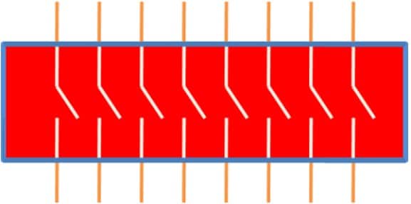
The DIP switch contains several tiny switches. Each tiny switch can be operated independently. A simplistic representation of a DIP switch with eight positions is shown below. When you move the actuator to the ON position, it will close the switch and vice-versa.
Tipos de interruptores DIP
Los interruptores DIP vienen en varias opciones. Hay interruptores NC, NO, de varias etapas, etc.
Un interruptor NC es aquel en el que los pequeños interruptores del módulo DIP estarán en ON en un estado normal.
Un interruptor NO es aquel en el que los pequeños interruptores del DIP estarán en OFF cuando pongas el interruptor en estado normal.
También hay un interruptor DIP ON-FF-ON donde puede haber tres etapas de los actuadores.
También encontrará configuraciones SPDT y DPDT de interruptores DIP. Deberá elegir la que sea más adecuada para su aplicación.
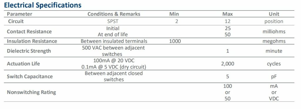
Especificaciones del interruptor DIP
Veamos las especificaciones más importantes de un interruptor DIP, que le ayudarán a elegir el interruptor DIP adecuado de forma fiable para sus aplicaciones.
- Tipo de circuito - La mayoría de los interruptores DIP que se encuentran son del tipo SPST (Single Pole, Single Throw). También hay disponibles muchas otras configuraciones, como las de polo único y doble tiro, y las de polo doble y doble tiro.
- Número de posiciones - El número de posiciones se refiere al número de pequeños interruptores en el módulo. Los que suelo utilizar tienen 4 u 8 posiciones. Encontrarás múltiples opciones en las tiendas.
- Corriente nominal - La cantidad de corriente que puede manejar cada pequeño interruptor en el DIP. No utilice siempre más del 60% de la corriente máxima. No debe utilizar el interruptor DIP cerca de la corriente máxima, ya que reduce la vida útil esperada del interruptor.
- Tensión nominal - La tensión nominal menciona la tensión máxima que puedes aplicar a través del interruptor DIP. Si estás utilizando un Arduino UNO, el voltaje máximo que puedes aplicar es de 5 V. Por lo tanto, debe elegir al menos 5 V como la clasificación mínima del Arduino UNO.
- Mechanical Life / Electrical Life – The number of operations supported by the DIP switch before the switching operations become unreliable.
- The On state resistance – The on-state resistance will be significantly less ( in a few milli Ohms range).
A continuación se muestra una captura de pantalla de la hoja de datos de un interruptor DIP, donde se pueden ver la mayoría de los parámetros enumerados para nuestra referencia.
Applications Of DIP Switches
Hay varias aplicaciones para el interruptor DIP. He enumerado algunas de ellas a continuación. Dime para qué utilizas el interruptor DIP.
- Puede generar dos a la potencia N valores distintos utilizando el interruptor DIP para fijar el precio. N representa el número de pequeños interruptores presentes en el interruptor DIP. Por lo tanto, utilizando un interruptor DIP con cuatro posiciones, puedes crear 16 valores diferentes.
- Para configurar las opciones del temporizador para la iluminación automática.
- Asigna diferentes IDs a múltiples nodos de control remoto.
- Ajuste el modo de funcionamiento del controlador de habitación (modo vacaciones, modo odio, modo fiesta, modo ecológico, etc.)
- Configurar las tarjetas de control para que actúen como repetidor, concentrador o monitor.
- Utilízalo como código de seguridad para entrar en el garaje.
- Establezca diferentes canales de frecuencia de comunicación para las radios inalámbricas.
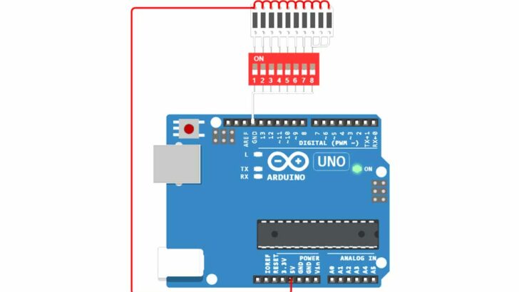
Connect The DIP Switch To An Arduino
In this section, we will build a project using Arduino UNO and a DIP switch. You will control the LEDs connected to the Arduino using the DIP switch.
Wiring of the DIP switch and the LEDs
The following picture shows the complete wiring of the DIP switch and the LEDs. To keep things simple, we will be using only 4 of the 8 switches of the DIP switch. But you can easily use the remaining ones in the same manner, if you want to.
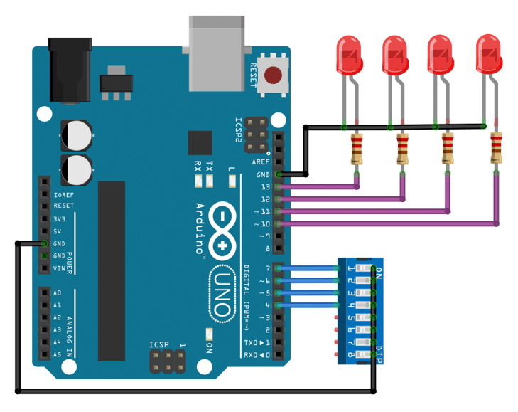
Start the wiring by connecting the switches 1 to 4 of the DIP to the GPIO pins 7 to 4 of the Arduino (blue wires). Next connect all other pins of the DIP switch to ground (black wire).
Now, connect all the short pins of the LEDs (Cathode) to ground (GND) using a black wire. Finally, we need to connect al the long pins (individually) to the GPIO pins 13 to 10 of the Arduino. Each connection needs a current limiting resistor of 220Ω.
In the next section we will write the code to control the LEDs via the DIP switch.
Code to control the LEDs via DIP switch
In the code below, we control 4 LEDs using 4 of the 8 switches of the DIP switch. The state of each switch determines whether the corresponding LED is on or off. The loop continuously checks the state of each switch and updates the LEDs accordingly.
Have a look at the complete code first, before we discuss its details.
// Control 4 LEDs with a DIP switch

const int LED1 = 13;
const int LED2 = 12;
const int LED3 = 11;
const int LED4 = 10;

const int S1 = 7;
const int S2 = 6;
const int S3 = 5;
const int S4 = 4;

void switch_led(int switchPin, int ledPin) {
  int state = digitalRead(switchPin);
  digitalWrite(ledPin, state == HIGH ? LOW : HIGH);
}

void setup() {
  pinMode(LED1, OUTPUT);
  pinMode(LED2, OUTPUT);
  pinMode(LED3, OUTPUT);
  pinMode(LED4, OUTPUT);

  pinMode(S1, INPUT_PULLUP);
  pinMode(S2, INPUT_PULLUP);
  pinMode(S3, INPUT_PULLUP);
  pinMode(S4, INPUT_PULLUP);
}

void loop() {
  switch_led(S1, LED1);
  switch_led(S2, LED2);
  switch_led(S3, LED3);
  switch_led(S4, LED4);

  delay(100);
}
Constants and Variables
We start by defining the constants and variables. Here, we define the pin numbers for the LEDs and the DIP switches.
const int LED1 = 13;
const int LED2 = 12;
const int LED3 = 11;
const int LED4 = 10;

const int S1 = 7;
const int S2 = 6;
const int S3 = 5;
const int S4 = 4;
Switch LED function
El switch_led() function is responsible for controlling an LED based on the state of a DIP switch. It takes two parameters: the pin number of the switch and the pin number of the LED.
Inside the function, we read the state of the switch using digitalRead() and then set the state of the LED using digitalWrite(). If the switch is HIGH, the LED is set to LOW (off), and if the switch is LOW, the LED is set to HIGH (on).
void switch_led(int switchPin, int ledPin) {
  int state = digitalRead(switchPin);
  digitalWrite(ledPin, state == HIGH ? LOW : HIGH);
}
Note that the logic is reversed, since we are using the internal pullups of the GPIO pins connected to the switch. This means, when the switch is open it is pulled to HIGH and when the switch is closed it is read as LOW. There for we switch the LEDs in reversed logic. If the switch is HIGH, it is in its off state and therefore we set the LED to LOW (off).
If you want to learn more about how to use switches and buttons with an Arduino, have a look at our tutorial Push-Button And Arduino. Similarly, if you want to know more about LEDs have a look at How To Blink An LED Using Arduino.
Setup function
En el setup() function, we set the pin modes for the LEDs as OUTPUT and the DIP switches as INPUT_PULLUP. The INPUT_PULLUP mode enables the internal pull-up resistors for the switches, so they read HIGH when the switches are open and LOW when the switches are closed.
void setup() {
  pinMode(LED1, OUTPUT);
  pinMode(LED2, OUTPUT);
  pinMode(LED3, OUTPUT);
  pinMode(LED4, OUTPUT);

  pinMode(S1, INPUT_PULLUP);
  pinMode(S2, INPUT_PULLUP);
  pinMode(S3, INPUT_PULLUP);
  pinMode(S4, INPUT_PULLUP);
}
You should avoid connecting switches directly to GPIO pins without using pull-up or pull-down resistors. Those can be external resistors (typically 1kΩ or 10kΩ), or you can use the internal pull-up resistors, as we have done here.
Loop function
El loop() function is where the main logic of the program resides. It calls the switch_led() function for each switch and LED pair, updating the LEDs based on the switch states. We also include a small delay of 100 milliseconds to debounce the switches and prevent rapid toggling.
void loop() {
  switch_led(S1, LED1);
  switch_led(S2, LED2);
  switch_led(S3, LED3);
  switch_led(S4, LED4);

  delay(100);
}
This code allows us to control the state of 4 LEDs using a DIP switch. The LEDs will mirror the state of the corresponding switches, turning on when the switch is closed and turning off when the switch is open.
Refined Code Example
The code presented above works fine but will be cumbersome to use if we use all 8 switches or more to control more LEDs or other devices. We would need to define individual constants for each of them, which is tedious.
The following code uses arrays and loops instead, which will make it much easier to extend the code to more switches and LEDs. It works exactly the same but is much shorter
// Control 4 LEDs with a DIP switch

const int LEDS[] = { 13, 12, 11, 10 };
const int SWITCHES[] = { 7, 6, 5, 4 };
const int N = 4;

void switch_led(int switchPin, int ledPin) {
  int state = digitalRead(switchPin);
  digitalWrite(ledPin, state == HIGH ? LOW : HIGH);
}

void setup() {
  for (int i = 0; i < N; i++) {
    pinMode(LEDS[i], OUTPUT);
    pinMode(SWITCHES[i], INPUT_PULLUP);
  }
}

void loop() {
  for (int i = 0; i < N; i++) {
    switch_led(SWITCHES[i], LEDS[i]);
  }
  delay(100);
}
Constants and Variables
We start by defining two arrays, LEDS y SWITCHES, which hold the pin numbers for the LEDs and switches, respectively. The constant N is set to 4, representing the number of LEDs and switches.
const int LEDS[] = { 13, 12, 11, 10 };
const int SWITCHES[] = { 7, 6, 5, 4 };
const int N = 4;
Switch LED function
El switch_led() function is the same as before. It takes two parameters: switchPin y ledPin and sets the state of the LED connected depending on the state of the switch.
void switch_led(int switchPin, int ledPin) {
  int state = digitalRead(switchPin);
  digitalWrite(ledPin, state == HIGH ? LOW : HIGH);
}
Setup function
En el setup() function, we iterate over the LEDS y SWITCHES arrays to set the pin modes. The LED pins are set as OUTPUT, as we will be writing to them, and the switch pins are set as INPUT_PULLUP, enabling the internal pull-up resistors.
void setup() {
  for (int i = 0; i < N; i++) {
    pinMode(LEDS[i], OUTPUT);
    pinMode(SWITCHES[i], INPUT_PULLUP);
  }
}
Loop function
En el loop() function, we iterate over the LEDS y SWITCHES arrays again. For each iteration, we call the switch_led() function to update the state of the corresponding LED based on the state of the switch. We then introduce a delay of 100ms before the next iteration.
void loop() {
  for (int i = 0; i < N; i++) {
    switch_led(SWITCHES[i], LEDS[i]);
  }
  delay(100);
}
And that’s it. Now you know how to use a DIP switch.
Frequently Asked Questions
I have compiled a list of the most frequently asked questions about projects using Arduino and DIP switches. If you have any other questions, please post them in the comments section.
1) ¿Qué son los interruptores DIP?
DIP stands for Dual-In-Line Package. A DIP switch contains a set of switches arranged and packed in a single package. The switches help to handle 8 GPIO inputs easily.
You can use DIP switches to program Arduino UNO to set different modes. You can also control the LEDs or relays using DIP switches without any MCUs.
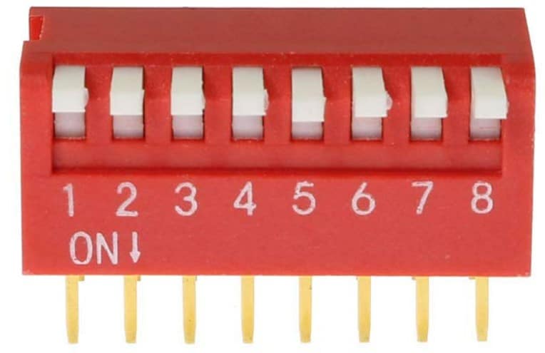
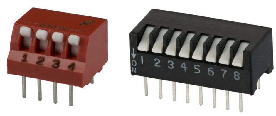
El interruptor DIP de la imagen superior consta de 8 botones.
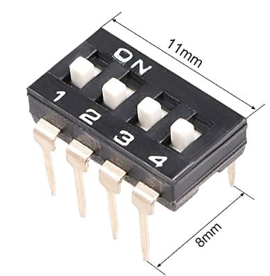
2) ¿Qué es un interruptor DIP de 4 pines?
Un interruptor DIP de 4 pines consta de 4 interruptores independientes en un solo paquete. Este es un ejemplo de un interruptor DIP de 4 pines.
3) ¿Cuánta corriente puede manejar un interruptor DIP?
The DIP switch can handle currents in the mA range. Here is one example datasheet of a DIP switch, which can handle up to 100 mA of continuous current. The current rating will be higher for a continuous current. For a switching current, the ratings will be slightly lower.
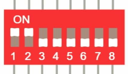
4) ¿Cómo se sabe si un interruptor DIP está en ON o en OFF?
The DIP switch is ON when the slider is near the ON marker on the switch. In the image below, the DIP switch has eight switches in it. Switches 1 and 2 are ON. The remaining eight switches are OFF.
Conclusión
In this article, I explained the basic concepts of a DIP switch. I am hoping that the article was easy to follow.
Hemos cubierto los diferentes tipos de interruptores DIP disponibles. También hemos revisado las especificaciones que uno debe buscar al decidir la elección correcta del interruptor DIP.
Espero que haya disfrutado del artículo. Si tienes alguna sugerencia para mejorar el artículo, estaré encantado de escucharla.

I am Puneeth. I love tinkering with open-source projects, Arduino, ESP32, Pi and more. I have worked with many different Arduino boards and currently I am exploring, Arduino powered LoRa, Power line communication and IoT.