Servo motors are widely used in various applications. In this blog post, we will explore the differences between positional and continuous servos and help you understand which one is best suited for your project.
Positional servos, as the name suggests, are designed to move to a specific position and hold that position until a new signal is received. They are commonly used in applications where accuracy and stability are crucial. These servos have a limited range of motion, typically around 180 degrees, and are ideal for applications that require precise control over the motor’s position, such as robotic arms, RC car steering, and drone control.
Continuous servos, on the other hand, are designed to rotate continuously in either direction. Unlike positional servos, they do not have a specific position to hold. Instead, they are used in applications where continuous motion is required, such as wheeled robots or pan-tilt camera systems.
A very popular servo that is available as a positional or continuous type, is the SG90. In the following, we look at specifics of SG90 Micro Servos, how to connect them, and the differences in control for the positional and the continuous type.
Supplies needed
Makerguides.com is a participant in the Amazon Services LLC Associates Program, an affiliate advertising program designed to provide a means for sites to earn advertising fees by advertising and linking to products on Amazon.com. As an Amazon Associate we earn from qualifying purchases.
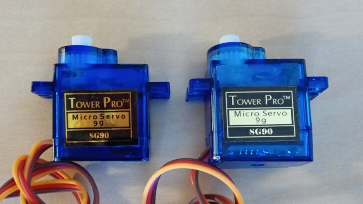
For this project you will need the following supplies. Note that positional and continuous servos can appear identical on the outside! Look for a description or a label that says continuous or 360 degrees for continuous servos, and 180 degrees or positional for positional servos.

Arduino Uno

Dupont Wire Set

USB Cable for Arduino UNO
Positional SG90 Servo
Continuous SG90 Servo
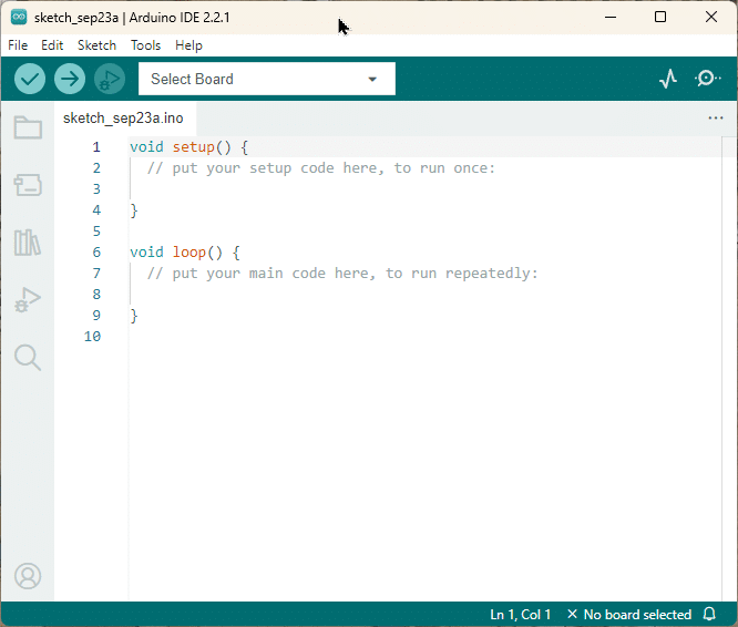
Arduino IDE
Specifics of SG90 Micro Servos
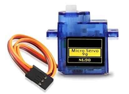
The SG90 micro servo is a popular and widely used servo motor in various applications. It is known for its compact size, affordability, and versatility. Here are some key specifics of the SG90 micro servo:
Size and Weight
The SG90 micro servo is a small-sized servo motor, measuring approximately 23mm x 12.2mm x 29mm. It is lightweight, weighing around 9 grams, making it suitable for projects where space and weight are a concern.
Tensión de funcionamiento
The SG90 micro servo operates on a voltage range of 4.8V to 6V. This makes it compatible with most common power sources, such as LiPo batteries or power supplies.
Torque and Speed
The SG90 micro servo offers a decent amount of torque for its size. It typically provides a torque of around 1.6 kg/cm at 4.8V and 2.2 kg/cm at 6V. The speed of the servo is approximately 0.12 seconds per 60 degrees at 4.8V and 0.10 seconds per 60 degrees at 6V.
Control Signal
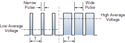
The SG90 micro servo uses a standard PWM (Pulse Width Modulation) control signal for its operation. It requires a control signal with a frequency of 50Hz and a pulse width between 1ms to 2ms. The pulse width determines the position of the servo shaft, in the case of a positional servo, or speed of rotation in the case of a continuous servo.
Compatibility
The SG90 micro servo is compatible with most microcontrollers and development boards, such as Arduino, Raspberry Pi, and ESP32. It can be easily controlled using software libraries and programming languages commonly used in the maker community.
Connecting the SG90 Micro Servo
Follow these steps to connect the SG90 Micro Servo:
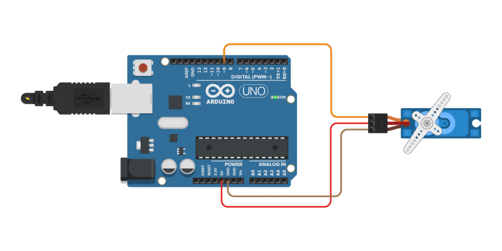
- Start by connecting the power supply to the servo. The SG90 Micro Servo operates on a voltage range of 4.8V to 6V. Connect the positive (red) wire of the servo to the 5V pin of your microcontroller or power supply.
- Then connect the negative (black or brown) wire of the servo to the ground (GND) pin.
- Next, connect the control signal wire of the servo to PIN 9 on your microcontroller. The control signal wire is usually colored yellow, white or orange.
Note that if you connect multiple servos to an Arduino, especially when the servos are under load, the Arduino may not be able to provide enough power to all the servos simultaneously. This can result in erratic servo movements, reduced performance, or cause the Arduino to reset or freeze! In this case you will need an extra power supply for the servos.
Now that you know how to connect the SG90 Micro Servo, let’s explore the key features of positional servos in the next section.
Key Features of Positional Servos
Positional servos, also known as standard servos, are widely used in various applications due to their precise control over angular position. Here are some key features of positional servos:
Angular Control: Positional servos allow for precise control over the angular position of the servo shaft. They can rotate to a specific angle within a defined range, typically between 0 and 180 degrees.
Position Feedback: These servos come equipped with position feedback mechanisms, such as potentiometers or encoders, which provide information about the current position of the servo shaft. This feedback enables accurate positioning and control.
Torque: Positional servos are designed to provide high torque output, allowing them to exert a significant amount of force. This makes them suitable for applications that require moving or manipulating objects with resistance.
Stability: Positional servos are known for their stability and ability to hold a position once it has been reached. They have built-in circuitry that helps maintain the desired position, even under external forces or load changes.
Overall, positional servos are ideal for applications that require precise angular control, stability, and high torque output. They are commonly used in robotics, RC vehicles, industrial automation, and other projects where accurate positioning is crucial.
Code to Control Positional Servos
Typically you don’t control a servo by actually writing the code to generate the required PWM signals but you use a library. The most popular library for this purpose is the Servo library. In its documentation you will find the following code example:
#include <Servo.h>

Servo myservo;  // create servo object to control a servo
int pos = 0;    // variable to store the servo position

void setup() {
  myservo.attach(9);  // attaches the servo on pin 9 to the servo object
}

void loop() {
  for (pos = 0; pos <= 180; pos += 1) { // goes from 0 degrees to 180 degrees
    myservo.write(pos);              // tell servo to go to position in variable 'pos'
    delay(15);                       // waits 15ms for the servo to reach the position
  }
  for (pos = 180; pos >= 0; pos -= 1) { // goes from 180 degrees to 0 degrees
    myservo.write(pos);              // tell servo to go to position in variable 'pos'
    delay(15);                       // waits 15ms for the servo to reach the position
  }
}
This code is supposed to move the servo from the 0 degree to the 180 degree position and then back.
However, if you try this with some brands of SG90 servos this will often not work! In my case, for instance, the servo does not stop at the 0 degree angle but performs a full rotation in the wrong direction to get to the next position. The reason is that manufactures sometimes are not adhering strictly to the timing standards for the PWM signal.
Finetuning angles
So, we will have to do some finetuning to get this to work. Below is an improved code example:
#include <Servo.h>

const int range = 780;
const int mid = 1600;  // 90 degrees
Servo servo;

void setup() {
  servo.attach(9);  // PIN 9
}

void rotate(int angle, int wait) {
  angle = map(angle, 0, 180, mid - range, mid + range);
  servo.writeMicroseconds(angle);
  delay(wait);
}

void loop() {
  rotate(0, 1000);
  rotate(90, 1000);
  rotate(180, 1000);
  rotate(90, 1000);
}
Note that the behaviour is somewhat different. Instead of incrementally changing the position, we move directly from 0 degrees, to 90 degrees, then to 180 degrees and finally back to 90 degrees, with a waiting time of 1000ms in between. This is just for simplicity. You could change the code to do the same as the example above by changing the loop function to:
void loop() {
  for (int angle = 0; angle <= 180; angle += 1) {
    rotate(angle, 15);
  }
  for (int  angle = 180; angle >= 0; angle -= 1) {
    rotate(angle, 15);
  }
}
The important part here is the rotate() function, which takes an angle (and a waiting time) and maps this angle to pulse length. In theory, a pulse length of 1000ms is fully counter-clockwise (0 degrees), 2000ms is fully clockwise (180 degrees), and 1500ms is in the middle (90 degrees). This is for the most common positional servos that have an angle range from 0 to 180 degrees.
Finetuning the mid point
In practise, the pulse lengths actually needed are different and therefore the servo does not move as expected. We start by setting the mid-point, the 90 degree angle, which should be at 1500ms pulse length. For this, you attach the horn to the servo, set the constant mid to 1500 and change the loop function to:
void loop() {
  rotate(90, 1000);
}
Depending on the toothing, the horn might not be perfectly at the angle, where you want it to be. For instance, let’s assume you want 90 degrees look like the picture below, but the horn is actually slightly off center.
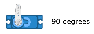
We can fix this by adjusting the mid constant until we get the perfect alignment. In the code example shown above, I had to set mid=1600 to achieve this.
Finetuning the end points
Next, we adjust the 0 and 180 degree positions by changing the range constant. For this, we modify the code in the loop as follows
void loop() {
  rotate(0, 1000);
  rotate(180, 1000);
}
We then let the servo run, observe the end positions and adjust the range constant, starting with a value of 500, until we get the angles depicted below.


For instance, in the code example above, I had to set the range=780, to achieve this for my servos. Note that these adjusted parameter values for the pulse length deviate quite substantially from the standard values. So quite a bit of finetuning is needed to get the servos to do what you want them to do.
For more details have a look at our tutorial on How to control servo motors with Arduino.
Next we will have a look at the key features of continuous servos.
Key Features of Continuous Servos
Continuous servos, also known as continuous rotation servos or 360 degree servos, rotate continuously in either direction. Unlike positional servos, which have a limited range of motion of typically 180 degrees, continuous servos rotate without any physical stops. Here are some key features of continuous servos:
Speed Control: Continuous servos allow for precise speed control. By adjusting the pulse width modulation (PWM) signal sent to the servo, you can control the speed at which it rotates. This makes continuous servos ideal for applications that require variable speed control, such as wheeled robots.
Bi-directional Rotation: Continuous servos can rotate in both clockwise and counter-clockwise directions.
No Position Feedback: Unlike positional servos, continuous servos do not provide position feedback. This means that you cannot accurately control the position or angle of the servo shaft. Instead, you can only control the speed and direction of rotation.
Continuous servos offer unique advantages over positional servos, particularly in applications that require continuous motion and variable speed control. However, they lack the ability to accurately control the position of the servo shaft.
Code to Control Continuous Servos
The control code for a continuous servo is essentially identical to the one for a positional servo. We just change the names of the variables and constants to clarify the intent of the code:
#include <Servo.h>

const int maxspeed = 700;
const int stop = 1500;
Servo servo;

void setup() {
  servo.attach(9); // PIN 9
}

void rotate(int speed, int wait) {
  speed = map(speed, -100, +100, stop - maxspeed, stop + maxspeed);
  servo.writeMicroseconds(speed);
  delay(wait);
}

void loop() {
  rotate(0, 1000);
  rotate(-100, 1000);
  rotate(+100, 1000);
}
An important difference, however, is in the mapping. There we map speeds from -100% to +100% (in contrast to angles) to the pulse durations required for the control of the servo.
As before, theoretically, a pulse length of 1000ms would be used for full speed in counter-clockwise direction, 2000ms would be full speed in clockwise direction, and for a pulse length of 1500ms the servo should not move.
For my servos, a pulse duration of 1500ms indeed resulted in a stop of the servo. Maximum speeds, however, were achieved at 1500ms-700ms = 800ms and 1500ms + 700ms = 2200ms, which above the standard values of 1000ms and 2000ms.
Similar to the finetuning of a continuous servo, you start by finding the mid-point, which is the value for the stop constant, where the servo does not move. Then you increase the maxspeed constant (starting at 500ms) until you don’t observe any further improvements in rotation speed.
For more details have a look on our tutorial on How to Control a 360 Degree Servo Motor with Arduino.
Choosing Between Positional and Continuous Servos
When it comes to choosing between positional and continuous servos, here a short summary of the factors to consider.
Positional Servos
Positional servos are designed to rotate to a specific angle and hold that position. Consequently, positional servos are ideal for tasks that involve moving objects to specific locations or angles.
Key features of positional servos include:
- Position Control: Positional servos allow you to set the desired angle of rotation, and they will maintain that position until instructed otherwise.
- Feedback Mechanism: These servos typically include a potentiometer or an encoder that provides feedback on the servo’s current position.
- Torque: Positional servos are known for their high torque capabilities, making them suitable for applications that require moving heavy loads.
Continuous Servos
On the other hand, continuous servos are designed to rotate continuously in either direction. Therefore, continuous servos are ideal for tasks that involve spinning wheels, propellers, or other rotating components.
Key features of continuous servos include:
- Continuous Rotation: Unlike positional servos, continuous servos can rotate continuously in either direction.
- Speed Control: These servos typically include a speed control mechanism, allowing you to adjust the rotational speed.
- No Position Control: Continuous servos do not have position control like positional servos. They do not hold a specific angle.
Choosing the Right Servo
If you need precise control over the servo’s position and high torque capabilities, a positional servo would be the right choice. On the other hand, if you require continuous motion and speed control, a continuous servo would be more suitable.
Conclusión
In this post, we looked at the differences between positional and continuous servos, their key features and how to control them.
Positional servos are designed to rotate within a specific range of angles, making them ideal for applications that require precise positioning. On the other hand, continuous servos offer continuous rotation in either direction, making them suitable for applications that require continuous motion, such as wheel motors for small robots or vehicles.
When deciding between positional and continuous servos, consider the specific requirements of your project. If you need precise control over the servo’s position, a positional servo is the way to go. However, if you require continuous motion or the ability to modify the servo for specific applications, a continuous servo is the better choice.
In this blog post, we focused on the specifics of SG90 micro servos, which are commonly used in hobbyist projects due to their small size and affordability. However, the concepts discussed apply to other servo motors as well.
In summary, understanding the key features and differences between positional and continuous servos is essential for selecting the right servo motor for your project. Consider the specific requirements and applications, and choose accordingly. Happy servo motor experimenting!
Note
We implement a special rotate() function that performs a mapping of angles or speeds to pulse durations. The attach() function of the Servo library has two additional parameters (min and max) that achieve a similar effect.
attach(pin, min, max)
However, this does not allow you to adjust the mid-point and for speeds ranging from -100% to +100% you would need a separate mapping anyway. We therefore opted for the more generic solution presented above.
Stefan is a professional software developer and researcher. He has worked in robotics, bioinformatics, image/audio processing and education at Siemens, IBM and Google. He specializes in AI and machine learning and has a keen interest in DIY projects involving Arduino and 3D printing.