You cannot imagine the world these days without GPS.
Millions of people use GPS to navigate from one place to another every day.
GPS also plays a vital role in defence and space applications. The Low Earth Orbit (LEO) satellites used for media communication and weather forecasting depend on GPS for their functionality.
GPS is also helpful in locating parcels, pets, kids, and even lost hikers!
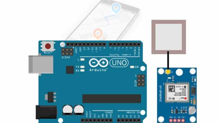
This tutorial will build an Arduino GPS module project using the Neo-6M module from u-Blox.
I have provided you with a full step-by-step guide, connection diagrams, and Arduino example code to build a project where you can also track the position and speed of any object.
At the end of the article, you will find a collection of the most frequently asked questions on the GPS modules with answers.
Let’s get started!
Components Needed To Build Arduino Neo-6M GPS Project
Hardware Components
- Dupont wire x 1 set
- Arduino USB cable (for powering Arduino and programming) x 1
Software
Makerguides.com is a participant in the Amazon Services LLC Associates Program, an affiliate advertising program designed to provide a means for sites to earn advertising fees by advertising and linking to products on Amazon.com.
Basics of The Neo-6M GPS Module
In this section, we will see the pinout details, features and some useful tools to complete the GPS projects.
Let us have a look at the features of the Neo-6M GPS module.
What are the features of the Neo-6M GPS module?
The Neo-6M GPS module is a variant of the GPS receivers supplied by u-Blox. The Neo-6M receiver has the following features.
- Operates from 2.7 V to 3.6 V
- Provides several serial interface options (SPI, UART, USB, etc)
- Supports RTC feature with built-in RTC crystal
- Supports External wakeup feature
- AEC-Q100 Qualified
- Supports 50 channels
- Supports GPS in L1 band
- The time to first fix is about 27 seconds (cold Start)
- Industry best sensitivity of -161 dBm
- Supports position update rate of 5 Hz ( 5 times a second)
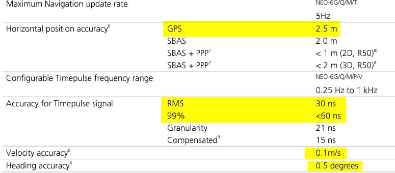
- Accuracy
- Horizontal Position – 2.5 m
- Velocity – 0.1 m/s
-> Read our guide about What You Can Build with Adruino.
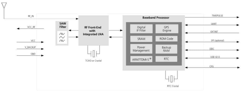
Block Diagram of the GPS module
You can find a SAW filter (a critical component in the RF link for GPS receivers), an RF front end with integrated LNA (Low Noise Amplifier) and a baseband processor to process the signals.
Here is the pinout of the Neo-6 chip.
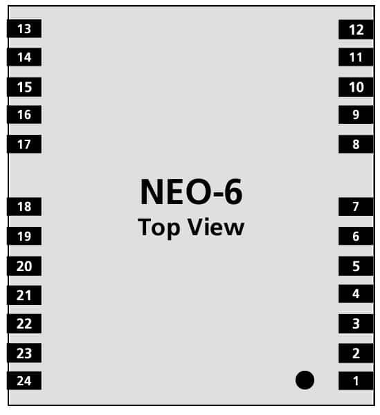
You can find the pin details of the Neo-6M IC here.
| No | Module | Name | I/O | Description |
| 1 | All | Reserved | I | Reserved |
| 2 | All | SS_N | I | SPI Slave Select |
| 3 | All | TIMEPULSE | O | Timepulse (1PPS) |
| 4 | All | EXTINT0 | I | External Interrupt Pin |
| 5 | All | USB_DM | I/O | USB Data |
| 6 | All | USB_DP | I/O | USB Data |
| 7 | All | VDDUSB | I | USB Supply |
| 8 | All | Reserved | See Hardware Integration Manual Pin 8 and 9 must be connected. | |
| 9 | All | VCC_RF | O | Output Voltage RF section Pin 8 and 9 must be connected together. |
| 10 | All | GND | I | Ground |
| 11 | All | RF_IN | I | GPS signal input |
| 12 | All | GND | I | Ground |
| 13 | All | GND | I | Ground |
| 14 | All | MOSI/CFG_COM0 | O/I | SPI MOSI / Configuration Pin. Leave open if not used. |
| 15 | All | MISO/CFG_COM1 | I | SPI MISO / Configuration Pin. Leave open if not used. |
| 16 | All | CFG_GPS0/SCK | I | Power Mode Configuration Pin / SPI Clock. Leave open if not used. |
| 17 | All | Reserved | I | Reserved |
| 18 | All | SDA2 | I/O | DDC Data |
| 19 | All | SCL2 | I/O | DDC Clock |
| 20 | All | TxD1 | O | Serial Port 1 |
| 21 | All | RxD1 | I | Serial Port 1 |
| No | Module | Name | I/O | Description |
| 22 | All | V_BCKP | I | Backup voltage supply |
| 23 | All | VCC | I | Supply voltage |
We are using the module which comes with the chip assembled already.
Let us closely see the module, the critical parts and the connector details of the Neo-6M GPS board.
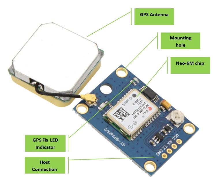
The host connector has four pins. Here are the details of the four pins. You will need these pins to complete the connection with the Arduino.
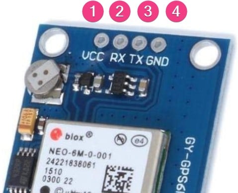
| Pin | Label | Function |
| 1 | VCC | Input Power pin. Connect 5 V from Arduino to the VCC pin |
| 2 | RX | GPS Module’s UART Rx pin. Connect to the Arduino Tx pin |
| 3 | TX | GPS Module’s UART Tx pin. Connect to the Arduino Rx pin |
| 4 | GND | Ground Connection |
Good Resources to understand GPS and NEMA format
- About NEMA – https://www.gpsworld.com/what-exactly-is-gps-nmea-data/
- GPS basic working Principle – https://trakkitgps.com/how-gps-works/
In the next section, we will connect the Arduino UNO to the GPS module.
Step-By-Step Instructions To Connect The Neo-6M With Arduino UNO
In this section, we will build a project using Arduino UNO and the GPS receiver module from u-Blox.
The connections are easy to take significantly less time to complete.
Let’s get started with the hardware connections!
How To Connect The Neo6M GPS Module To The Arduino UNO?
Below is the step-by-step connection guide to complete the Arduino and the Neo-6M u-Blox GPS Module, and following that I have provided some example code for you to use as well.
In this project, you will interface the Neo-6M GPS module over the serial port to the Arduino UNO.
Step 1: Start with the GND connections
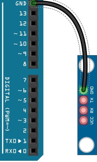
You can choose any GND pins on the Arduino to complete the GND connections.
It is a good practice to connect the GND pins first.
Step 2: Connect the UART Tx pin
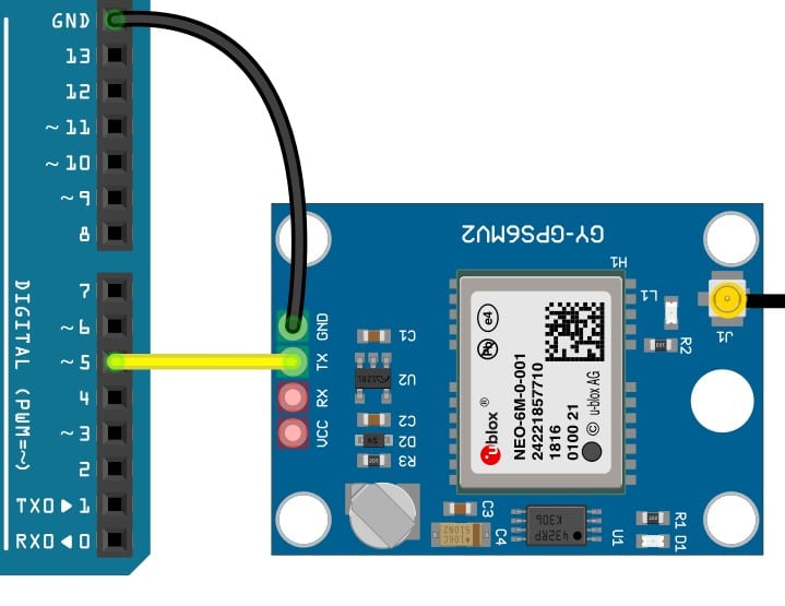
Connect the UART transmit pin (Tx) of the GPS module to the Arduino UNO Pin 5.
You can choose any pin on the Arduino using the software serial.
Please update the Arduino sketch to reflect the same pins on both code and the connections.
Step 3: Connect the UART Rx pin.
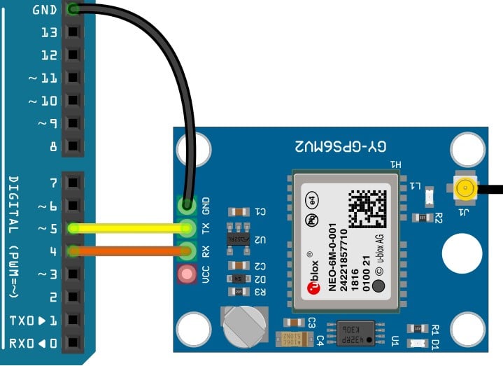
Connect the GPS module’s UART receive pin (Rx) to the Arduino UNO Pin 4. You can choose any pin on the Arduino using the software serial.
Please update the Arduino sketch to reflect the same pins on both code and the connections.
Step 4: Connect the Power pin.
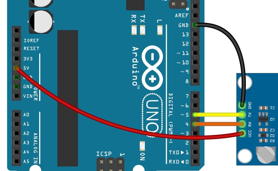
Connect the GPS module’s VCC to the Arduino UNO’s 5 V pin. This completes the necessary connection.
Step 5: The Complete Connection
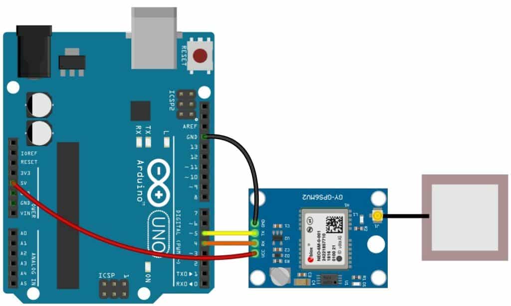
Congratulations! You have completed all the essential connections required for the Arduino and the Neo-6M GPS module project.
In the next section, we will program the Arduino UNO with the sketch necessary to communicate with the Neo-6M module.
Arduino Code Example For The Neo-6M GPS Module
In this section, you will find the Arduino sketch required by the Arduino to communicate
With the Neo-6M GPS module.
We are going to use the TinyGPSPlus library for the project. To install the TinyGPSPlus module, follow the instructions below.
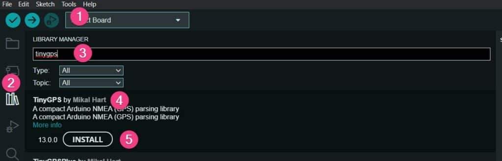
1. Open the Arduino IDE

2. Click on Tools and choose Manage Libraries.
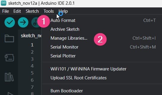
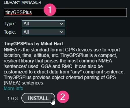
3. Enter TinyGPSPlus in the search bar and hit Enter
Once you find the TinyGPSPlus library, click on the Install button to install the library onto your PC.
Now you are ready to load the example code below and test the connections.
The complete Arduino code for the Neo-6M GPS Module
//Source: https://www.electronicwings.com/arduino/gps-module-interfacing-with-arduino-uno


#include "TinyGPS++.h"
#include "SoftwareSerial.h"

/* Create object named bt of the class SoftwareSerial */
SoftwareSerial GPS_SoftSerial(5, 4);/* (Rx, Tx) */
/* Create an object named gps of the class TinyGPSPlus */
TinyGPSPlus gps;

volatile float minutes, seconds;
volatile int degree, secs, mins;

void setup() {
  Serial.begin(9600); /* Define baud rate for serial communication */
  GPS_SoftSerial.begin(9600); /* Define baud rate for software serial communication */
}

void loop() {
  smartDelay(1000); /* Generate precise delay of 1ms */
  unsigned long start;
  double lat_val, lng_val, alt_m_val;
  uint8_t hr_val, min_val, sec_val;
  bool loc_valid, alt_valid, time_valid;
  lat_val = gps.location.lat(); /* Get latitude data */
  loc_valid = gps.location.isValid(); /* Check if valid location data is available */
  lng_val = gps.location.lng(); /* Get longtitude data */
  alt_m_val = gps.altitude.meters();  /* Get altitude data in meters */
  alt_valid = gps.altitude.isValid(); /* Check if valid altitude data is available */
  hr_val = gps.time.hour(); /* Get hour */
  min_val = gps.time.minute();  /* Get minutes */
  sec_val = gps.time.second();  /* Get seconds */
  time_valid = gps.time.isValid();  /* Check if valid time data is available */
  if (!loc_valid)
  {
    Serial.print("Latitude : ");
    Serial.println("*****");
    Serial.print("Longitude : ");
    Serial.println("*****");
  }
  else
  {
    DegMinSec(lat_val);
    Serial.print("Latitude in Decimal Degrees : ");
    Serial.println(lat_val, 6);
    Serial.print("Latitude in Degrees Minutes Seconds : ");
    Serial.print(degree);
    Serial.print("\t");
    Serial.print(mins);
    Serial.print("\t");
    Serial.println(secs);
    DegMinSec(lng_val); /* Convert the decimal degree value into degrees minutes seconds form */
    Serial.print("Longitude in Decimal Degrees : ");
    Serial.println(lng_val, 6);
    Serial.print("Longitude in Degrees Minutes Seconds : ");
    Serial.print(degree);
    Serial.print("\t");
    Serial.print(mins);
    Serial.print("\t");
    Serial.println(secs);
  }
  if (!alt_valid)
  {
    Serial.print("Altitude : ");
    Serial.println("*****");
  }
  else
  {
    Serial.print("Altitude : ");
    Serial.println(alt_m_val, 6);
  }
  if (!time_valid)
  {
    Serial.print("Time : ");
    Serial.println("*****");
  }
  else
  {
    char time_string[32];
    sprintf(time_string, "Time : %02d/%02d/%02d \n", hr_val, min_val, sec_val);
    Serial.print(time_string);
  }
}

static void smartDelay(unsigned long ms)
{
  unsigned long start = millis();
  do
  {
    while (GPS_SoftSerial.available())  /* Encode data read from GPS while data is available on serial port */
      gps.encode(GPS_SoftSerial.read());
    /* Encode basically is used to parse the string received by the GPS and to store it in a buffer so that information can be extracted from it */
  } while (millis() - start < ms);
}

void DegMinSec( double tot_val)   /* Convert data in decimal degrees into degrees minutes seconds form */
{
  degree = (int)tot_val;
  minutes = tot_val - degree;
  seconds = 60 * minutes;
  minutes = (int)seconds;
  mins = (int)minutes;
  seconds = seconds - minutes;
  seconds = 60 * seconds;
  secs = (int)seconds;
}
The lines below set the software serial pins.
If you had to connect the UART pins to other Arduino UNO pins, please change the below line accordingly.
In our example, we have used Pins 5 and 4 for the UART communication.
/* Create object named bt of the class SoftwareSerial */
SoftwareSerial GPS_SoftSerial(5, 4);/* (Rx, Tx) */
If the connections and programming were successful, you would find GPS parameters in the serial terminal, such as latitude, longitude and time.
You may not receive the data soon if you are working indoors. I suggest moving closer to a window where you can see the open sky.
You will start to see the location information soon after you have the position locked by the GPS module.
In the next section, you will find answers to a collection of questions on the GPS module and Arduino.
FAQs About The GPS Module Neo-6M And Arduino Projects
I have included a list of the most frequently asked questions about projects built using Arduino and the Neo-6M GPS modules from u-Blox.
If you have more questions, please post them in the comments section.
I will be glad to answer them.
1. How do I connect my Neo 6M to my Arduino?
The Neo-6M is a GPS module which can track up to 22 satellites in view. The module consumes a typical power of about 25 mA while providing the best sensitivity for acquiring and tracking GPS signals.
The Neo-6M module can communicate with Arduino over UART.
You can either use a dedicated serial port or create a software serial port to make Neo 6M and Arduino communicate with each other.
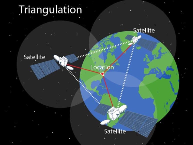
2. How does GPS neo 6M work?
GPS module Ne0-6M tracks GPS satellites on the L1 band. The GPS receiver can track up to 50 channels.
The received signals from the GPS satellites are processed, and the extracted data are Ephemeris data and Almanac data.
You use this data to find the time and how far a particular satellite is.
Once you have at least three satellites in view, the module will do triangulation and find the position of the module itself.
3. How accurate is Arduino GPS?
The accuracy of the GPS modules depends on many factors. For example, a first moving vehicle in a sub-urban area needs a position faster rather than a precision of centimetres.
Accuracy is critical when you are performing specified jobs using robots in logistics.
The Neo-6M accuracy also depends on the number of satellites it tracks.
The horizontal accuracy is 2.5 m, and the velocity accuracy is 0.1 m/s.
4. Is Neo-6M GPS accurate?
The Neo-6 Modules from u-Blox are accurate. The datasheet specifications are one of the best in the industry.
The accuracy related to speed, position and time are as below.
5. How do I add the TinyGPS library to Arduino?
TinyGPS library is a versatile tool to parse the NMEA message from GPS modules.
To install the TinyGPS library on your PC, follow the steps below.
- Open Arduino IDE. Click on Tools. Select the Manage Libraries option.
- You are now in the library options window
- Type “tinyGPS” in the search bar and hit ‘Enter’
- Select the library TinyGPS from the results
- Click on the Install button.
The library is now ready to use in your future Arduino GPS projects.
Conclusion
In this article, we covered the basics of using GPS with Arduino.
We looked at the key features of the GPS receiver module Neo-6M from u-Blox, and also covered a few terminologies and tools which help process the GPS data.
I have good experience working with GPS receivers for commercial vehicles and space applications (satellites, missiles, etc.).
I will gladly answer your questions if you want to know more!
If you have any feedback to improve the article, please share it in the comments section.
Your valuable input helps me to improve the article quality and bring more helpful content in the future.
Please remember to share the GPS Neo-6M article with your fellow Arduino enthusiasts.

I am Puneeth. I love tinkering with open-source projects, Arduino, ESP32, Pi and more. I have worked with many different Arduino boards and currently I am exploring, Arduino powered LoRa, Power line communication and IoT.
Ralph
Friday 29th of March 2024
your code is the cleanest and most accurate neo-6m example code I have seen.
Stefan Maetschke
Saturday 30th of March 2024
Thanks, much appreciated.
Bill Bell
Wednesday 6th of December 2023
Very encouraging article, thank you. Although I have worked with many computer systems, for several decades, I have never got into anything like an Arduino. I am wondering whether this system would perform well enough for providing the latitudes and longitudes of the headstones in a cemetery, for use in findagrave.com. (I am quite serious.) When you use a print statement where do you see the output; how does it appear?
Anyway, thanks again.
Bill Bell
Thursday 7th of December 2023
@Stefan Maetschke, thank you for your reply.
Stefan Maetschke
Wednesday 6th of December 2023
Well, the horizontal resolution of the Neo-6M is only 2.5m (under optimal conditions). So, in practice it is probably not accurate enough to distinguish between two nearby gravestones.
The print statements are sent via the USB cable to the connected computer. This is mostly for debugging. In practice you would connect a display (LCD, TFT, ...) to the Arduino to show the coordinates. Very easy to do.
But if you just need the GPS coordinates any good mobile phone can do this ;)