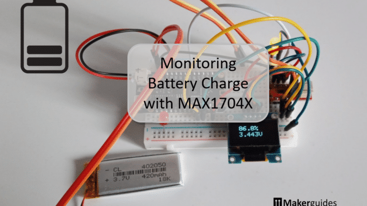
In this tutorial you will learn how to monitor LiPo battery charge levels using the MAX1704X. The hardware and code examples are for an ESP32 but work the same for an ESP8266 or Arduino.
LiPo batteries are great for battery powered projects and are commonly used for outdoor or mobile applications such as weather monitoring, surveillance or robotics. But running on batteries means you need to know when to recharge.
Estimating the charge of a LiPo battery and its remaining runtime is however surprisingly difficult. LiPo batteries have highly nonlinear discharge curves with a very sudden drop-off at the end. Have a look at the following discharge curve.
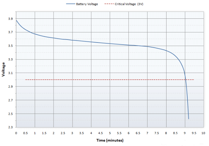
Even worse, the discharge curve depends on the ambient temperature and the current you draw from the battery. This makes it very difficult to get good estimates on relative charge and the remaining running time of a LiPo battery.
The MAX17043 is an advanced battery fuel gauge developed to solve this problem. In this tutorial you will learn how to use the MAX17043 to measure the voltage and relative charge of a LiPo battery with an ESP32. I will also show you how to configure and handle low battery alerts.
But let’s start with the required parts.
Required Parts
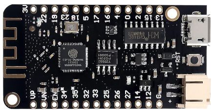
For this tutorial, I am using an older ESP32 board (ESP32 lite), which has been deprecated but you can still get it for a low price. That’s the one listed below. There is a successor model with improved specs, which you can find here.
But most ESP8266 and other ESP32 boards should work as well. I like the ESP32 lite because of the low price and the battery connector with built-in recharging capability. This means you can run the ESP32 on battery and charge the LiPo via the USB port – very handy.
If you want to use an Arduino, you should use a board that runs on 3.3V such as the Arduino Pro Mini (ATmega328-3.3V), since we are going to use a single LiPo battery (3.7V) here. I also listed an OLED but any display that supports I2C communication and runs on 3.3V will be fine.
There are two versions of the MAX1704X. The MAX17043 listed here is for a single LiPo cell, while the MAX17044 is for two LiPo cells (in series). However, I could not find a breakout board for MAX17044 anywhere and we are therefore going to use MAX17043. But that means you need a microcontroller that runs on 3.3V or a buck booster to generate higher voltages.
MAX17043 LiPo Fuel Gauge
ESP32 lite
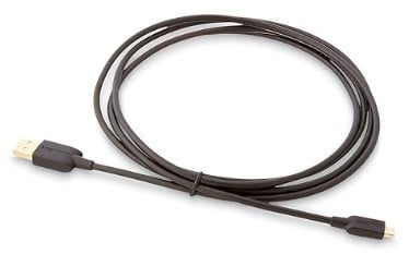
USB Data Cable

Dupont Wire Set

Breadboard

Resistor & LED kit
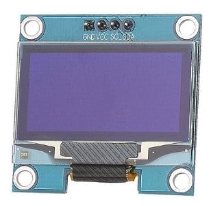
OLED Display
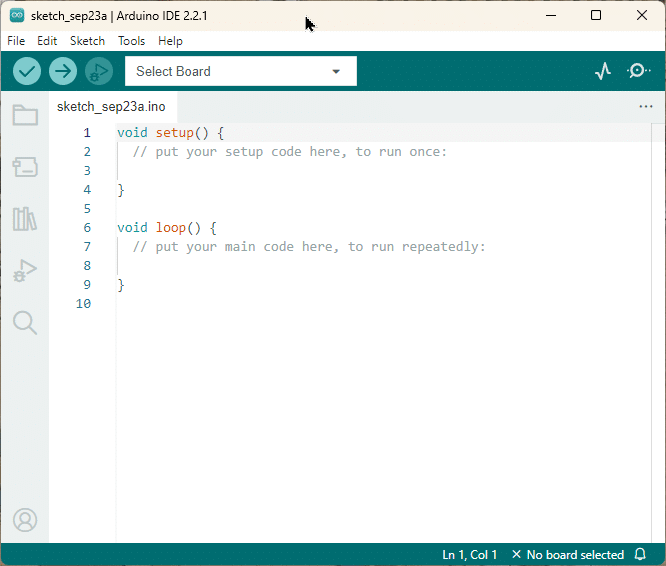
Arduino IDE
Makerguides.com is a participant in the Amazon Services LLC Associates Program, an affiliate advertising program designed to provide a means for sites to earn advertising fees by advertising and linking to products on Amazon.com. As an Amazon Associate we earn from qualifying purchases.
Specification of the MAX1704X Fuel Gauge
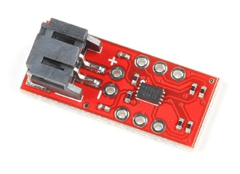
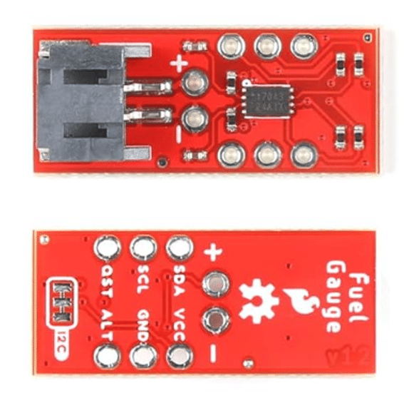
The MAX17043/MAX17044 is an ultra-compact, fuel-gauge systems for lithium-ion (Li+) batteries. The actual IC is tiny and the picture below show a typical breakout board for the chip, which makes it much easier to connect.
There are two version of the chip. The MAX17043 is configured to measure the charge of a single lithium cell, while MAX17044 is configured for a dual-cell 2S pack. The chip uses a LiPo battery-modeling scheme, called ModelGauge to track the battery’s relative state-of-charge (SOC) continuously over a widely varying charge/discharge profile.
Here are the specifications according to the Datasheet of the MAX17043/MAX17044:
- Battery Type: 3.7V Li-polymer/Li-ion battery
- 1 Cell (MAX17043) or 2 Cells (MAX17044)
- Precision Voltage Measurement
- ±12.5mV Accuracy for 5V (MAX17043)
- ±30mV Accuracy for 10V (MAX17044)
- Accurate Relative Capacity (RSOC)
- No Offset Accumulation on Measurement
- No Full-to-Empty Battery Relearning Necessary
- External Alarm/Interrupt for Low-Battery Warning
- I2C interface
- Operating Current: 50 µA
- Input Voltage (VCC): 3.3V~6.0V
Pinout
As mentioned above, the MAX1704X is a tiny IC and we therefore use the breakout board listed in the required parts. You can find the Pinout for this board below:
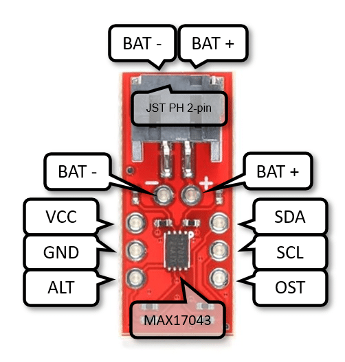
The board has a 2-pin JST connector to connect the LiPo battery. But there is also two pins (BAT+ and BAT-), where you can connect the battery. The input voltage range is between 2.5V to 4.5V. The nominal voltage of a single cell LiPo Battery is around 3.7V. Fully charged, the voltage is at around 4.2V. So a single cell LiPo falls into the input voltage range.
Power to the board is provided via the VCC and GND pin. The maximum VCC is 5.5V but recommended is 3.3V. Note that there different version of the board with different options (battery or MCU) how to provide VCC. I recommend you use the 3.3V of your microcontroller.
The ALT pin is the alert pin. This pin is normally HIGH but becomes LOW if the battery relative charge drops below a configurable percentage threshold, e.g. 10%. You can connect this pin to an interrupt pin of your microcontroller to react to low battery levels.
The QST pin is for quick-start input. It allows you to reset the MAX17043 through hardware. A rising edge on this pin will initiate a hardware reset. But you can also reset via software, and that is what we are going to do.
I2C Interface
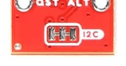
SDA and SCL are the pins for the I2C interface. The I2C address of the MAX17043 is 0x36. The breakout board has two 2.2kΩ pull-up resistors connected to the SDA and SCL lines, so you don’t need separate pull-up resistors.
Note that there is a 3-pad jumper at the lower part of the board. You can cut the jumpers to disable the pull-up resistors, if you connect multiple I2C devices. For more details have a look here.
And that’s all about the MAX17043. Next let’s have a look at the libraries available to read data from the MAX170X IC.
MAX170X Libraries
There are many libraries for using the MAX17043 with an ESP32/ESP8266 or Arduino. Namely, there are the libraries by Porrey, Lucadentella, Sparkfun, Adafruit and Nlamprian. All of them are all essentially wrappers around the functionality of the MAX1704X chip and are very similar.
I tried the Sparkfun library and the library by Porrey. Both worked but in this tutorial, I will show you exclusively code based on the Porrey library. However, if you prefer a different one, it should be fairly straightforward to swap it out.
Functions of the MAX170X library
Below a quick overview of the functions you will find in the MAX170X library by Porrey:
| begin(TwoWire*) | Creates a FuelGauge instance. |
| uint8_t address(); | Returns I2C address of the IC. |
| float voltage(); | Returns a measurement of the battery’s voltage in milli-volt |
| float percent(); | Returns the battery’s state of charge (SOC) in percent. |
| uint16_t version(); | Returns the version of the MAX170X IC. |
| uint8_t compensation(); | Returns a value used to optimize IC performance to different operating conditions |
| void compensation(uint8_t); | Sets a value for optimizing IC performance to different operating conditions |
| bool sleep(); | Forces the MAX170X IC to sleep mode. All operations are halted |
| bool isSleeping(); | Returns whether or not the MAX170X IC is in sleep mode |
| bool wake(); | Wakes the MAX170X IC from sleep mode |
| void reset(); | Resets the MAX170X IC |
| void quickstart(); | Restart battery charge calculations |
| bool alertIsActive(); | Returns whether a low battery alert is set |
| void clearAlert(); | Clears the low battery alert |
| uint8_t threshold(); | Returns the current threshold for the alert, e.g. 20% |
| void threshold(uint8_t); | Sets the threshold for the alert, e.g. 20% |
Installation of the MAX170X library
To install the MAX170X library by Porrey open the Library Manager and enter “MAX1704X” in the search box. You will find the “MAX1704X by Daniel Porrey”. See below:
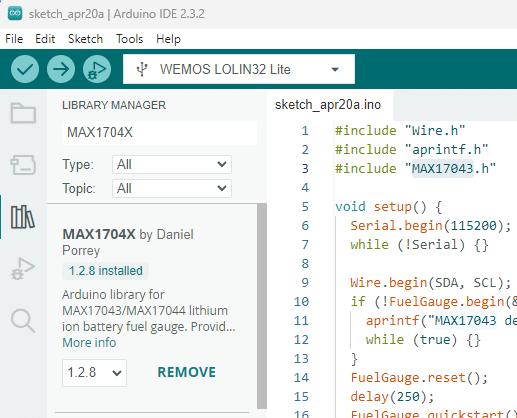
Press INSTALL button and your are done. As you can see in the screenshot above, I have the library already installed. You can install the other libraries, e.g. the Sparkfun or Adafruit as well, if you like. They don’t conflict.
In the next two sections, I show you first how to connect the MAX17043 to your microcontroller and then how to use the library to read battery data.
Connecting MAX17043 to ESP32
Connecting the MAX17043 to a microcontroller is very simple. First connect 3.3V and GND of the microcontroller to VCC and GND of the MAX17043 (red and blue wires). If you have a 5V Arduino, you can also connect 5V to VCC.

Next connect the I2C interface (SCL, SDA). The default pins for I2C on the EPS32 lite are 23 (SDA) and 19 (SCL). That is what is depicted above (green and yellow wires). In case of an Arduino, you would connect SDA -> A4 and SCL -> A5. Make sure to get these connections right, since it is easy to confuse them and the board will then not work.
Finally, we connect the LiPo battery. Plus and Minus of the battery are connected to corresponding connectors of the ESP32 and the MAX17043. The nice thing about the ESP32 board is that you can run it from the battery and at the same time connect the board via the USB cable to your computer. If it is connected, the battery is charged. The MAX17043 can remain connected while charging and will continue to report voltages and charge levels.
Note that there have been reports that the MAX17043 boards from some suppliers don’t work. My board from AliExpress is working fine and the one listed in the required parts should be fine as well. Though, I have not tested that specific board.
Reading Battery Charge from MAX17043
The following simple code example shows you how to read the battery voltage and relative charge using the MAX17043. Have a quick glance first and then we discuss the code in more detail.
#include "Wire.h"
#include "MAX17043.h"

void setup() {
  Serial.begin(115200);
  Wire.begin(SDA, SCL);
  if (!FuelGauge.begin(&Wire)) {
    Serial.println("MAX17043 NOT found.\n");
    while (true) {}
  }
  FuelGauge.reset();
  delay(250);
  FuelGauge.quickstart();
  delay(125);
}

void loop() {
  float volts = FuelGauge.voltage();
  float pcnt = FuelGauge.percent();
  Serial.printf("%.0fmV (%.1f%%)\n", volts, pcnt);
  delay(3000);
}
Include Libraries
We start by including the Wire and the MAX17043 library. The Wire Library is needed to configure the I2C interface. Should you have a MAX17044, you would include MAX17044.h, instead of MAX17043.h. The MAX170X library by Porrey has both header files.
Setup function
In the setup() function, we initialize the serial communication at a baud rate of 115200. We then start the I2C communication using the Wire.begin(SDA, SCL) function.
I explicitly define the pins for I2C using Wire.begin(SDA, SCL). This allows you to use pins other then the default pins for I2C and it also supresses a “Wire.begin()" message on the Serial monitor that is otherwise created by the library (see here).
Next we initiate the MAX17043 via FuelGauge.begin(&Wire). If the FuelGauge sensor is not found, a message is printed to the Serial monitor, and the program enters an infinite loop.
Otherwise, we reset the FuelGauge followed by a delay of 250ms and do a quickstart followed by a delay of 125ms. This sequence is taken from the example code that comes with the MAX17043 library. I am not entirely sure, if these delays are required but I left them in.
void setup() {
  Serial.begin(115200);
  Wire.begin(SDA, SCL);
  if (!FuelGauge.begin(&Wire)) {
    Serial.println("MAX17043 NOT found.\n");
    while (true) {}
  }
  FuelGauge.reset();
  delay(250);
  FuelGauge.quickstart();
  delay(125);
}
Loop function
The loop() function continuously reads the voltage and percentage charge of the LiPo battery. The voltage and percentage values are then printed to the serial monitor using Serial.printf() with a delay of 3 seconds between each reading.
void loop() {
  float volts = FuelGauge.voltage();
  float pcnt = FuelGauge.percent();
  Serial.printf("%.0fmV (%.1f%%)\n", volts, pcnt);
  delay(3000);
}
If you upload and run this code you should see the following output on your Serial Monitor:
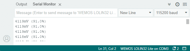
Note that the Arduino in contrast to the ESP32 does not support the printf function. You will have to use a sequence of print() statements instead. To avoid this, we will use the aprintf library in the following code examples. For more details have a look at our tutorial How To Print To Serial Monitor On Arduino.
Print more Data with aprintf
The following code example prints all the information we can get from the MAX17043 chip to the Serial Monitor. The structure of the code is the same as above. But there are a few minor changes, I want to point out.
#include "Wire.h"
#include "aprintf.h"
#include "MAX1704X.h"

MAX1704X monitor = MAX1704X(MAX17043_mV);

void setup() {
  Serial.begin(115200);
  Wire.begin(SDA, SCL);
  if (!monitor.begin(&Wire)) {
    aprintf("MAX1704X NOT found.\n");
    while (true) {}
  }
  monitor.reset();
  delay(250);
  monitor.quickstart();
  delay(125);
}

void loop() {
  aprintf("---------------------------------\n");
  aprintf("Voltage  %.0fmV\n", monitor.voltage());
  aprintf("Percent  %.1f%%\n", monitor.percent());
  aprintf("Address  0x%02x\n", monitor.address());
  aprintf("Version  %d\n", monitor.version());
  aprintf("ADC      %d\n", monitor.adc());
  aprintf("Alert    %d\n", monitor.alertIsActive());
  aprintf("Sleeping %d\n", monitor.isSleeping());
  aprintf("Compensation 0x%02x\n", monitor.compensation());
  delay(3000);
}
Firstly, instead of using the predefined FuelGage object you can create your own fuel monitor object:
MAX1704X monitor = MAX1704X(MAX17043_mV);
In the constructor you can specify if you have a MAX17043 or a MAX17044 and then use the name “monitor” or anything else you like through the remainder of the code.
Secondly, I am using the aprintf library to print the data to the Serial Monitor. The aprint() function does the same as Serial.printf() but works the same on Arduino, ESP32 and ESP8266. It is also comes in handy for formatted output to displays – which you will see in the next section.
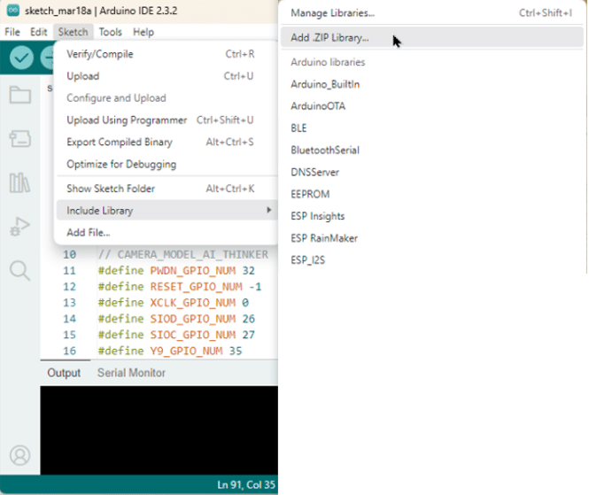
However, you have to install the aprintf library from a zip file. Download the zip-file here and then install it via Sketch -> Include Library -> Install .ZIP Library ... .
For more details on aprintf and the Serial Monitor have a look at our tutorial How To Print To Serial Monitor On Arduino. Once installed you should be able to run the code and should see the following output on your Serial Monitor:
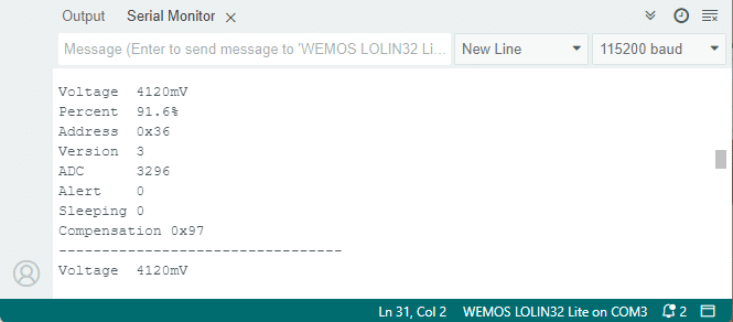
As you can infer from the output the board was currently charging the LiPo (Voltage = 4120mV), since for the Serial Monitor to work, the ESP32 needs to be connected via USB to the computer. In case of the ESP32 lite, this charges the attached LiPo battery.
In the next section, I show you how to connect an OLED and display battery information there, instead on the Serial Monitor.
Displaying Battery Charge on OLED
Displaying the battery charge level on the Serial Monitor is fine for testing but not very useful for a battery powered project. We typically what to display the current battery level somehow directly. That code be an LED bar or an LCD display. But in this example I am using a OLED, since they are very small and work nicely with 3.3V.
Wiring for OLED
The following diagram shows you how to connect the OLED (in addition to the already existing parts) to the project. Start by connecting 3.3V and GND from the Microcontroller to VCC and GND of the OLED (red and blue wires).
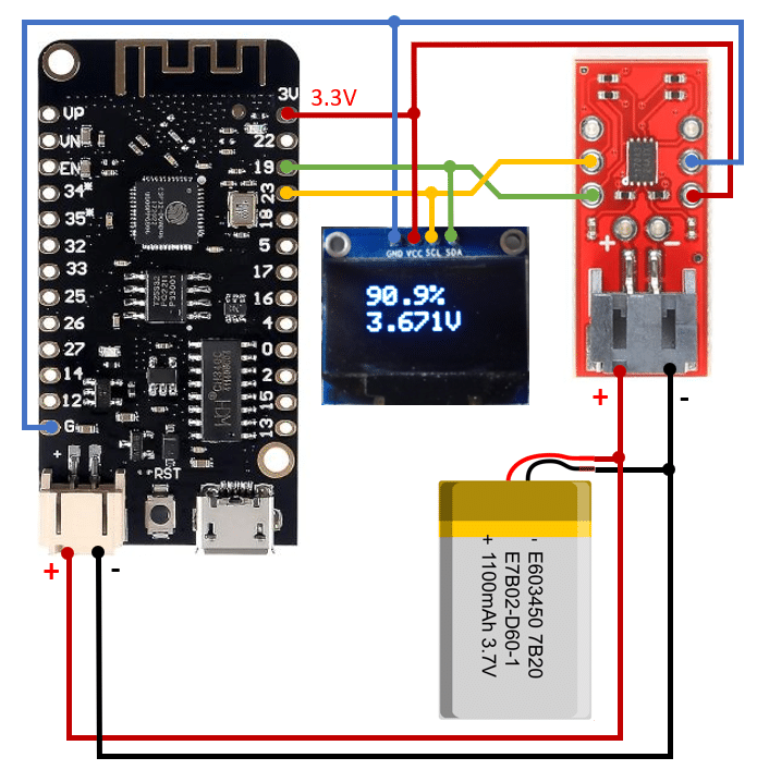
Then we connect the I2C wires (SDA, SCL) in parallel to the MAX17043 (yellow and green wires). The OLED and the MAX17043 share the same I2C bus and must have different I2C addresses. If you have issues, check the I2C addresses. My OLED has the I2C address 0x3C and the MAX17043 typically has the address 0x36. Also the pull-up resistors might be a problem. Remember the 3-pad jumper on the MAX17043 that you can use to disable the pullup resistors.
If you need more details on how to use an OLED display have a look at our tutorial on How to Interface the SSD1306 I2C OLED Graphic Display With Arduino.
Code for OLED
The following code displays battery voltage and relative charge on the OLED. As usual, have a quick look at the complete code first before we look at it more closely.
#include "Wire.h"
#include "aprintf.h"
#include "MAX17043.h"
#include "Adafruit_SSD1306.h"

Adafruit_SSD1306 disp(128, 64, &Wire, -1);

void setup() {
  Serial.begin(115200);
  Wire.begin(SDA, SCL);
  if (!FuelGauge.begin(&Wire)) {
    aprintf("MAX17043 NOT found.\n");
    while (true) {}
  }
  FuelGauge.reset();
  delay(250);
  FuelGauge.quickstart();
  delay(125);

  FuelGauge.threshold(20);
  FuelGauge.clearAlert();

  disp.begin(SSD1306_SWITCHCAPVCC, 0x3C);
  disp.setTextSize(2);
  disp.setTextColor(WHITE);
}

void loop() {
  float volts = FuelGauge.voltage() / 1000;
  float pcnt = FuelGauge.percent();
  bool alrt = FuelGauge.alertIsActive();

  disp.clearDisplay();
  disp.setCursor(20, 10);
  disp.print(fmt("%.1f%% %c", pcnt, alrt ? '!' : ' '));
  disp.setCursor(20, 30);
  disp.print(fmt("%.3fV", volts));
  disp.display();

  delay(3000);
}
Libraries and Display Setup
The code includes necessary libraries such as Wire.h, aprintf.h, MAX17043.h, and Adafruit_SSD1306.h. It then initializes an instance of the Adafruit_SSD1306 class for an OLED display with specific dimensions. I am using a 128×64 OLED here. If your OLED is of a different size, you will have to adjust the values here.
Adafruit_SSD1306 disp(128, 64, &Wire, -1);
Setup Function
In the setup() function, the serial communication is started at a baud rate of 115200. The I2C communication is initiated using the Wire.begin(SDA, SCL) function. The code checks if the MAX17043 IC is detected, and if not, it prints a message and enters an infinite loop. Next the fuel gauge is reset and a quick start is performed.
We also set a threshold for a low battery warning by calling FuelGauge.threshold(20). This means the threshold for the low battery alert is set to 20%. The highest level you can set is 32% and the lowest is 1%. After that we clear all existing alerts.
  FuelGauge.threshold(20);
  FuelGauge.clearAlert();
Finally, we initialize the OLED display. Make sure to use the I2C address of your OLED here. Mine is 0x3C and I have a black & white OLED, so I set the text color to WHITE.
  disp.begin(SSD1306_SWITCHCAPVCC, 0x3C);
  disp.setTextSize(2);
  disp.setTextColor(WHITE);
Loop Function
The loop() function continuously reads the battery voltage and percentage level using the FuelGauge.voltage() and FuelGauge.percent() functions. It also checks if any alerts are active using FuelGauge.alertIsActive().
  float volts = FuelGauge.voltage() / 1000;
  float pcnt = FuelGauge.percent();
  bool alrt = FuelGauge.alertIsActive();
The battery information is printed to the OLED using the fmt() function from the aprintf libary and the display() function of the Adafruit_SSD1306 library.
The fmt() function works like Serial.printf() but prints to a string buffer that is then returned. The disp.print() function of the OLED takes this string buffer and displays the content on the OLED.
  disp.clearDisplay();
  disp.setCursor(20, 10);
  disp.print(fmt("%.1f%% %c", pcnt, alrt ? '!' : ' '));
  disp.setCursor(20, 30);
  disp.print(fmt("%.3fV", volts));
  disp.display();
With the fmt() function you can use the same formatting and conveniently print to devices that do not support a printf()-like function. However, for the OLED don’t forget the disp.display() at the end, otherwise nothing will be displayed.
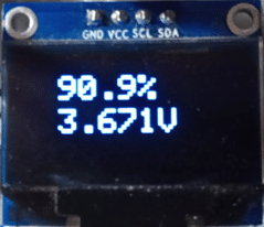
The OLED will show the battery percentage, voltage, and an alert indicator (!) if an alert is active. If everything is connected and implemented correctly you should see the following output:
In this example we have displayed a low battery alert on the OLED by polling the state of the alert pin every 3 seconds. Alternatively, we can use an interrupt handler to react to a low battery alert immediately. This is the topic of the next section.
Handling Low Battery Alerts of MAX17043
To demonstrate the handling of low battery event let’s add an LED to the circuit. This LED will light up if the battery charge drops below a predefined threshold.
We connect the positive side (long pin) of the LED to GPIO 25 of the ESP32. You can pick any other GPIO you like – just don’t forget to change the code below accordingly. The negative side of the LED is connected to GND (G) via a current limiting resistor of 68Ω.

Now comes the interesting part. The MAX17043 will generate a signal on the ALT pin when the battery charges drops below the threshold. More accurately the ALT pin will go from HIGH to LOW. We connect the ALT pin to GPIO 32 of the ESP32 and an interrupt handler will be called if the state of the ALT pin changes.
Let’s see how that is done in code!
Code for Low Battery Interrupt Handler
Most microcontrollers including the ESP32 allow you to attach an interrupt handler function to a pin. This causes the function to be executed when the pin changes its state. The code below is the same above with the addition of an interrupt handler function lowBattery(). There is also an additional definition for an ledPin and alrtPin, which we need to show and detect a low battery alert.
Below is the complete code and we will discuss its details in the sections below:
#include "Wire.h"
#include "aprintf.h"
#include "MAX17043.h"
#include "Adafruit_SSD1306.h"

const int alrtPin = 32;
const int ledPin = 25;

Adafruit_SSD1306 disp(128, 64, &Wire, -1);

void lowBattery() {
  digitalWrite(ledPin, HIGH);
}

void setup() {
  Serial.begin(115200);
  Wire.begin(SDA, SCL);
  if (!FuelGauge.begin(&Wire)) {
    aprintf("MAX17043 device was NOT found.\n");
    while (true) {}
  }
  FuelGauge.reset();
  delay(250);
  FuelGauge.quickstart();
  delay(125);

  FuelGauge.threshold(20);
  FuelGauge.clearAlert();

  disp.begin(SSD1306_SWITCHCAPVCC, 0x3C);
  disp.setTextSize(2);
  disp.setTextColor(WHITE);

  pinMode(ledPin, OUTPUT);
  pinMode(alrtPin, INPUT_PULLUP);
  digitalWrite(ledPin, LOW);
  attachInterrupt(alrtPin, lowBattery, FALLING);
}

void loop() {
  float volts = FuelGauge.voltage() / 1000;
  float pcnt = FuelGauge.percent();
  bool alrt = FuelGauge.alertIsActive();

  disp.clearDisplay();
  disp.setCursor(20, 10);
  disp.print(fmt("%.1f%% %c", pcnt, alrt ? '!' : ' '));
  disp.setCursor(20, 30);
  disp.print(fmt("%.3fV", volts));
  disp.display();

  delay(3000);
}
Constants and Variables
As mentioned above we firstly define two new constants, alrtPin and ledPin, which represent the pins for the alert signal and LED indicator respectively.
const int alrtPin = 32;
const int ledPin = 25;
Low Battery Function
The lowBattery() function is called when the battery charge falls below a certain threshold. It simply turns on the LED connected to ledPin. Note that the LED will stay on until the ESP32 is reset, even if the battery charge returns to a level above the threshold. But it is easy to change this behavior, if you need something different.
void lowBattery() {
  digitalWrite(ledPin, HIGH);
}
Setup Function
In the setup() function, the code initializes the serial communication, I2C bus, MAX17043 Fuel Gauge, OLED display, and sets up the pin modes for the LED and alert signal.
Most importantly, it also configures the interrupt to trigger the lowBattery() function on a falling edge. This means if the ALT pin of the MAX17043 goes low due to a low battery charge, we detect this falling edge on the alrtPin and call the lowBattery() function. Note that the lowBattery() function is called independently of the loop() function.
void setup() {
  ...
  attachInterrupt(alrtPin, lowBattery, FALLING);
}
If you want to learn more about interrupts have a look at our tutorials Push-Button And Arduino and Build Arduino Tachometer Using A3144 Hall Effect Sensor that have more applications and details.
Loop Function
The loop() function is the same as before. It continuously reads the battery voltage, percentage charge, and alert status from the MAX17043 IC. It then updates the OLED display with this information and checks for any alerts. If an alert is active, it displays an exclamation mark next to the battery percentage.
The important difference between the alert shown on the OLED and the alert signalled via the red LED is that the OLED is updated only every 3 seconds, while the LED will react immediately.
And that’s it. With these circuits and code you can monitor battery charge levels accurately and react to low battery alerts quickly.
Conclusions
The MAX1704X is a very handy little IC to monitor battery charge levels for battery powered projects. The two versions, the MAX17043 and the MAX17044 are essentially the same. Code and circuits presented above will work the same for both of them. The only difference is that the MAX17043 is designed to monitor the charge levels of a single LiPo (3.7V), while the MAX17044 is used when two LiPo (7.4V) are used in series.
A feature of the MAX1704X we haven’t talked about in this tutorial is the compensation feature. Apparently, it can optimize the IC performance for different lithium chemistries or different operating temperatures. But there is no information about the specifics and what values to use for compensation in the datasheet.
However, another nice feature of the MAX1704X that is documented, is the sleep mode. This is handy in conjunction with the deep sleep mode of the ESP32 (or Arduino/ESP8266). It allows you to put both, the microcontroller and the battery monitor in deep sleep to extend battery life.
Alternatively to the MAX1704X, you could use a voltage divider and measure the battery voltage via an analog input to implement a simple low battery warning system. For more details about that see our tutorial How to Monitor Battery Voltage for Battery Powered Projects. This is a cheaper but a much less reliable approach, especially if you want to estimate the remaining running time and recharge timely.
And now have fun ; )
Links
Here a few links I found useful when writing this tutorial:
- SparkFun MAX1704x Fuel Gauge Arduino Library
- LiPo Fuel Gauge (MAX1704X) Hookup Guide – SparkFun Learn
- ESP32 get data from max17043 | All About Circuits
- Battery Monitoring Done Right (Arduino & ESP32)
Frequently Asked Questions
How accurate is the MAX1704X Fuel Gauge in monitoring battery charge levels?
The MAX1704X Fuel Gauge is highly accurate, with a typical error of only ±1% over the entire temperature range.
Can the MAX1704X be used with other microcontrollers besides ESP32 and Arduino?
Yes, the MAX1704X can be used with a variety of microcontrollers as long as they support I2C communication.
Is it possible to customize the low battery alert threshold on the MAX1704X?
Yes, the low battery alert threshold can be customized to suit your specific requirements by adjusting the corresponding register values. However, the maximum threshold is 32% and the minimum is 1%.
Can the MAX1704X be used with different types of batteries besides LiPo?
While the MAX1704X is optimized for LiPo batteries, it can also be used with other types of batteries with some adjustments to the configuration settings.
How is the MAX1704X Fuel Gauge powered?
The MAX1704X Fuel Gauge can be powered directly from the battery it is monitoring but I recommend to power it from the microcontroller.
Can the MAX1704X monitor multiple batteries simultaneously?
No, the MAX1704X is designed to monitor a single battery at a time.
What is the communication interface used by the MAX1704X Fuel Gauge?
The MAX1704X Fuel Gauge communicates with the microcontroller using the I2C interface.
Is it possible to calibrate the MAX1704X for even greater accuracy?
Yes, the MAX1704X can be calibrated using software commands to improve accuracy based on specific application requirements. See the compensation() function of the MAX1704X library and the datasheet of the MAX1704X.
How does the MAX1704X handle battery overcharging protection?
The MAX1704X does not provide overcharging protection itself, but it can monitor the battery charge level to help prevent overcharging when used in conjunction with appropriate charging circuitry.
How does the MAX1704X handle battery discharging protection?
The MAX1704X does not provide battery discharging protection, but it can monitor the battery charge level to help prevent deep discharging when integrated with appropriate power management systems.
What is the typical operating voltage range of the MAX1704X Fuel Gauge?
The MAX1704X operates within a typical voltage range of 2.7V to 5.5V; suitable to monitor the typical voltage of a LiPo battery (3.7V).
What is the current consumption of the MAX1704X Fuel Gauge?
The typical current consumption of the MAX1704X is 50µA and it has a sleep mode with even lower power consumption of 1µA.
Stefan is a professional software developer and researcher. He has worked in robotics, bioinformatics, image/audio processing and education at Siemens, IBM and Google. He specializes in AI and machine learning and has a keen interest in DIY projects involving Arduino and 3D printing.