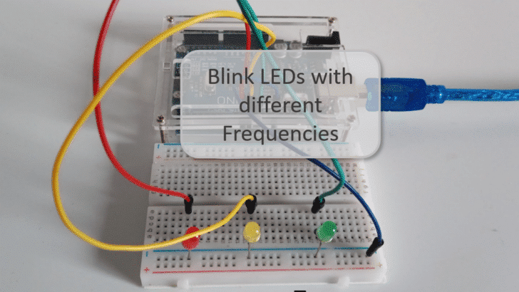
In this tutorial you will learn how to blink multiple LEDs together but with different frequencies or delays and duty cycles using an Arduino or ESP32.
Blinking a single LED is easy and one of the first examples you learn when starting with Arduino programming. However, blinking multiple LEDs independently with different frequencies can get quite tricky. In this tutorial we will use the ezOutput library to make that simple. I will also show you how to convert frequencies and duty cycles into delay times.
But before that, let’s have a look at the required parts.
Required Parts
Below the list of required parts. I used an Arduino Uno for this project but any other Arduino board, or ESP8266/ESP32 board will work just as well. And of course, if you already have LEDs and suitable resistors (220Ω), you don’t need to buy them.

Arduino Uno

USB Cable for Arduino UNO

Dupont Wire Set

Breadboard

Resistor & LED kit
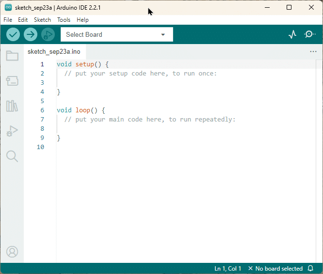
Arduino IDE
Makerguides.com is a participant in the Amazon Services LLC Associates Program, an affiliate advertising program designed to provide a means for sites to earn advertising fees by advertising and linking to products on Amazon.com. As an Amazon Associate we earn from qualifying purchases.
What is Frequency
Before we build the circuit and write the code, let’s have a quick chat about what Frequency actually is. This will simplify things later on. I think, the easiest definition of Frequency is the following:
Frequency is the number of times a pattern or event repeats itself within a second.
For instance, if an LED is switched on and off four times within a second, it would blink with a frequency of 4 Hertz (Hz). See the picture below, where we illustrate the switching signal for a LED.
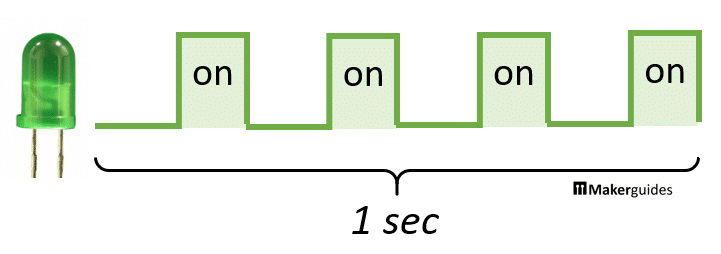
The event of switching the LED occurs 4 times within 1 second. Therefore the Frequency is 4 Hz. If we would switch the LED on and off 10 times within a second it would blink with a Frequency of 10Hz.
Commonly, the formula for frequency f is given as 1 divided by the time T it takes to complete one pattern (on switching event):
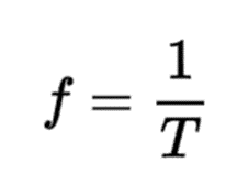
It’s the same thing, just the other way around ; ) For instance, if we switch the LED four times in one second (=4Hz), it means that it takes T =1/4 = 0.25 seconds for one switching event. Let’s put that in the formula above: 1/T = 1/0.25s = 4Hz.
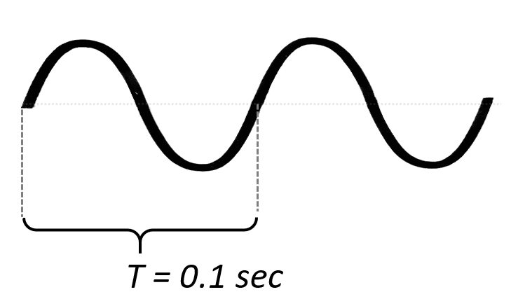
Frequency of a sine wave
Note that Frequency is not limited to rectangular pulses or switching events. We can compute the Frequency for any kind of repeating pattern or event. A frequent case is a sine wave, which we could use to pulsate (dim up and down) the brightness of an LED.
The example below shows a sine wave over two periods. Let’s say one period takes 0.1 seconds. The sine wave would then have a frequency of 10Hz.
Arduino’s tone() function
Note that the Arduino language has a built-in function called tone() that allows you to create a square wave signal with a frequency ranging from 16Hz up to 4MHz (using an Arduino Uno). However, for most applications where you want to blink LEDs even the lowest frequency of 16Hz is typically too fast. Often we want to blink slower than that and therefore cannot use tone().
Furthermore, tone() can only generate square waves with a 50% duty cycle. Let’s talk quickly about duty cycles and why that is a limitation, when we want to blink LEDs.
What is Duty Cycle
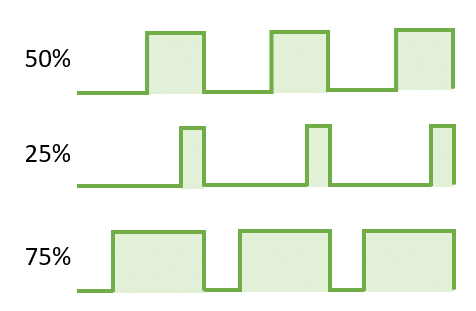
Let’s say you want to switch an LED on and off every second. We know now that would be a Frequency of 1Hz. But for how long during that second should be the LED on and how long should it be off? If we want it to be one for 50% of that second (=0.5), that would be a Duty Cycle of 50%. The definition of Duty Cycle is as follows:
Duty Cycle is the percentage of time a signal is high compared to the total time of one period.
So, if we switch the LED on only for 0.1 seconds during that second, and leave it off for the remaining 0.9 seconds, that would be a Duty Cycle of 10%. The picture below illustrates three square waves with different Duty Cycles
You might think you could use the PWM signal generated by analogWrite(), to blink LEDs with different Duty Cycles. However, again the frequency of the PWM signal is way too high (490Hz or 980Hz) to blink LEDs with, though you can change the frequency a bit. But it is a bit complex and still doesn’t give us the frequencies we usually want for blinking LEDs.
Blinking a single LED
Blinking a single LED with a given Frequency and Duty Cycle is easy. Let’s say we take our example from before and want to blink an LED with a Frequency 1Hz and a Duty Cycle of 50%. That means we have to switch the LED on for 0.5sec = 500msec, switch it off for another 0.5sec and repeat the cycle. That is essentially the well-known Blink example:
void loop() {
  digitalWrite(ledPin, HIGH);
  delay(500);
  digitalWrite(ledPin, LOW);
  delay(500);
}
We could do this a bit more elegant and flexible be implementing a function blink() to blink an LED with a given frequency f and a duty cycle dc:
void blink(int ledPin, float f, float dc) {
  digitalWrite(ledPin, HIGH);
  delay(1000 * dc / f);
  digitalWrite(ledPin, LOW);
  delay(1000 * (1 - dc) / f);
}
This is essentially the same as before but we are calculating the delay() based on the Frequency and the Duty Cycle. The delay for the LED on-phase is 1000 * dc / f based on the formula for frequency discussed above. The calculation for the off-phase is the same but with the remaining percentage of the duty cycle 1 -dc instead of dc.
A complete implementation for an LED connected to pin 9 that blinks a LED with a Frequency of 1Hz and a Duty Cycle of 50% would look like this:
int ledPin = 9;

void setup() {
  pinMode(ledPin, OUTPUT);
}

void blink(int ledPin, float f, float dc) {
  digitalWrite(ledPin, HIGH);
  delay(1000 * dc / f);
  digitalWrite(ledPin, LOW);
  delay(1000 * (1 - dc) / f);
}

void loop() {
  // 1 Hz, 50% duty cycle
  blink(ledPin, 1, 0.5);
}
This works nicely for a single LED but not for multiple LEDs with different frequencies! Try it. For instance, you can’t blink two LEDs one with a frequency of 1Hz and the other with a frequency of 2Hz, using the following code.
// This doesn't work!
void loop() {
  // 1 Hz, 50% duty cycle
  blink(ledPin1, 1, 0.5);
  // 2 Hz, 50% duty cycle
  blink(ledPi2, 2, 0.5);
}
The reason is that the delays (blinks) are not executed independently (in parallel) but in sequence.
If you want to blink multiple LEDs with different Frequencies and Duty Cycles things get a lot more complex. We have a tutorial on that: Control Multiple LEDs With Different Delays with Arduino. And if you need more background on how to blink LEDs, have a look at How To Blink An LED Using Arduino (4 Different Ways).
However, in this tutorial we are going to use the ezOutput library to control multiple blinking LEDs. This will simplify our task a lot.
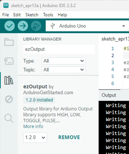
Using the ezOutput Library to blink LEDs
First, you need to install the ezOutput library through the library Manager before you can use it.
Main functions of the ezOutput Library
The ezOutput Library has various functions but we are going to need only three of them.
The ezOutput() function, takes a pin as input and creates an object ezOutput object around it. It provides the special pin functions we discuss next.
ezOutput(int pin)
With the blink() function you can switch a pin off (low) and on (high) for given time intervals (lowTime, highTime). The time interval are in milli-seconds.
void blink(unsigned long lowTime, unsigned long highTime)
You could do that with the delay() function as well, as we have seen in the example above. But the blink() function has the advantage that it can be called independently for different pins with different delays.
For that to happen, you need to call the loop() function of the ezObject() within the Arduino main loop.
void loop(void)
Sounds complicated? It is actually very easy. Let’s have a look at an example.
Blink three LEDs with different Delay Times
In the example code below, we are going to blink three LEDs connected to pins 11, 10, and 9 with three different frequencies and duty cycles.
#include "ezOutput.h"

ezOutput led1(11);
ezOutput led2(10);
ezOutput led3(9);

void setup() {
  led1.blink(500, 500);  // 1Hz,  dc=50%
  led2.blink(250, 250);  // 2Hz,  dc=50%
  led3.blink(10, 90);    // 10Hz, dc=90%
}

void loop() {
  led1.loop();
  led2.loop();
  led3.loop();
}
Libraries and Objects
We start by including the library “ezOutput.h”. Then we create three instances of the ezOutput class named led1, led2, and led3, each corresponding to a different LED connected to pins 11, 10, and 9 respectively.
#include "ezOutput.h"

ezOutput led1(11);
ezOutput led2(10);
ezOutput led3(9);
Setup Function
In the setup() function, we configure each LED to blink at a specific frequency and duty cycle using the blink() method of the ezOutput library. The time interval parameters passed to the blink() method are chosen in a way that they represent the frequency and duty cycle shown in the comments.
led1.blink(500, 500);  // 1Hz, 50% duty cycle
led2.blink(250, 250);  // 2Hz, 50% duty cycle
led3.blink(10, 90);    // 10Hz, 90% duty cycle
For instance for led1: if we want a blink frequency of 1Hz and a duty cycle of 50%, we have to switch the LED on for 500 msec and then off for another 500 msec. So, we pass an off-time of 500msec and an on-time of 500msec to blink to achieve this.
If we cut the delay times in half (250msec) our LED blinks twice as fast, which gives us a frequency of 2Hz for led2.
And if we want to change the duty cycle we need to change the ratio between the on- and off-times. So, for led3 the on-time is 90msec and the off time is 10msec, which gives us a duty cycle of 90% and a frequency of 10Hz.
Loop Function
In the loop() function, we continuously call the loop() method for each LED object. This ensures that each LED blinks independently and according to the blink parameters set in the setup() function.
void loop() {
  led1.loop();
  led2.loop();
  led3.loop();
}
This code works nicely but you have to convert blink frequencies and duty cycles into on-times and off-times for the blink function. We can make this more convenient by wrapping this part into a custom function.
Blink three LEDs with different Frequencies
So, in the following code example we do exactly the same as in the example above. Three LEDs at pins 11,10 and 9 will blink with Frequencies 1Hz, 2Hz, 10Hz and Duty Cycles 50%, 50%, 90%, respectively.
#include "ezOutput.h"

ezOutput led1(11);
ezOutput led2(10);
ezOutput led3(9);

void setFrequency(ezOutput &led, float f, float dc=0.5) {
  led.blink(1000*(1-dc)/f, 1000*dc/f);
}

void setup() {
  setFrequency(led1, 1, 0.5);
  setFrequency(led2, 2, 0.5);
  setFrequency(led3, 10, 0.9);
}

void loop() {
  led1.loop();
  led2.loop();
  led3.loop();
}
However, we added our own function setFrequency() that takes a given Frequency f and Duty Cycle dc into the lowTime and highTime parameters need for the blink() function.
void setFrequency(ezOutput &led, float f, float dc=0.5) {
  led.blink(1000*(1-dc)/f, 1000*dc/f);
}
Instead of blink() we can now call setFrequency() in the setup() function, directly with frequencies and duty cycles.
void setup() {
  setFrequency(led1, 1, 0.5);
  setFrequency(led2, 2, 0.5);
  setFrequency(led3, 10, 0.9);
}
Note that we provide duty cycles as a ration (0.9) and not as a percentage (90%). If you want that just divide the dc parameter by 100 with in the function.
With the setFrequency() function you now can work with frequencies and duty cycles, instead of on- and off-times, if it is more convenient.
This code will work for ESP32 and ESP8266 as well. Just select the correct board and change the pin constants accordingly. For instance, I am using the following pins on my WEMOS Lolin ESP32 lite board:
ezOutput led1(GPIO_NUM_22);
ezOutput led2(GPIO_NUM_19);
ezOutput led3(GPIO_NUM_23);
Next, let’s build the circuit with the three LEDs we want to blink.
Blink Circuit with three LEDs
The following picture shows the blink circuit with its three LEDs and current limiting resistors.
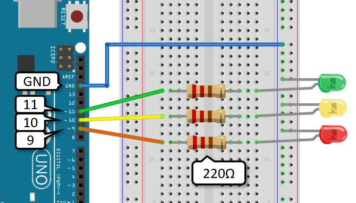
Building it is easy. First connect ground (GND) from the Arduino with the ground rail of the breadboard (blue wire). Then place the three LEDs. Make sure the short pins of the LEDs (Cathode) are connected to the ground rail.
Each of the long LED pins is connected to a current limiting resistor with 220Ω. The resistors are connected to the GPIO pins 11, 10 and 9 of the Arduino. And that’s it. There is your blink circuit.
The following short video clip shows the code and circuit in action. The LEDs blink with Frequencies of 1Hz, 2Hz, 10Hz and Duty Cycles of 50%, 50%, 90%, respectively.
Have fun playing with different frequencies duty cycles and more LEDs.
Conclusions
In conclusion, we have successfully learned how to blink multiple LEDs together with different frequencies or delays and duty cycles using an Arduino or ESP32. By understanding the concepts of frequency and duty cycle, we were able to create a circuit to control the LEDs and write the necessary code to achieve the desired blinking patterns.
The ezOutput library made this very simple and you could see that it easy to add your own custom functions to make it even more convenient.
If you have any questions have a look at the FAQ or write a comment.
Have fun ; )
Frequently Asked Questions
Q: Can I use different types of LEDs with varying frequencies in the same circuit?
A: Yes, you can use different types of LEDs with varying frequencies in the same circuit. Simply adjust the delay times in your code for each LED to achieve the desired blinking frequency.
Q: Is it possible to synchronize the blinking of multiple LEDs with different frequencies?
A: While it may be challenging to synchronize the blinking of multiple LEDs with significantly different frequencies, you can experiment with adjusting the delay times to achieve a visually appealing pattern. Consider using arrays or functions to manage the timing of each LED’s blinking sequence.
Q: Can I control the brightness of each LED along with its frequency?
A: Yes, you could use a PWM signal during the on-time of the LED to achieve this affect. However the ezOutput library does not support this directly. You would have to change and extend the code.
Q: How can I add more LEDs to the circuit and control them individually?
A: To add more LEDs to the circuit and control them individually, you can connect each LED to a separate digital pin on the Arduino or ESP32. Then, in your code, define variables for each LED’s delay time and duty cycle to control them independently.
Q: What is the maximum number of LEDs I can blink simultaneously with different frequencies?
A: The maximum number of LEDs you can blink simultaneously with different frequencies depends on the processing power and memory of your microcontroller. Typically, you can control multiple LEDs with varying frequencies as long as you have enough digital pins and memory available for the code.
Q: Can I use external components like transistors or shift registers to expand the number of controllable LEDs?
A: Yes, you can use external components like transistors or shift registers to expand the number of controllable LEDs. By using these components, you can effectively increase the number of LEDs you can control with your Arduino or ESP32, allowing for more complex lighting patterns. For more details have a look at our tutorial: More Arduino Outputs With 74HC595 Shift Register.
Q: How do I calculate the delay time for a specific frequency of blinking?
A: To calculate the delay time for a specific frequency of blinking, you can use the formula: delay time = 1 / (2 * frequency). For example, if you want an LED to blink at 2 Hz (with a 50% duty cycle), the delay time would be 250 milliseconds.
Q: How can I create more complex LED patterns, such as fading or pulsing effects?
A: To create more complex LED patterns like fading or pulsing effects, you can incorporate additional logic in your code using techniques such as linear interpolation for fading effects or sinusoidal functions for pulsing effects. By manipulating the brightness levels over time, you can achieve dynamic lighting patterns.
Q: Is it possible to synchronize the blinking of LEDs with external events or sensors?
A: Yes, it is possible to synchronize the blinking of LEDs with external events or sensors by incorporating sensor readings or event triggers in your code. For example, you can adjust the LED blinking frequency based on sensor inputs like light intensity, temperature, or motion detection.
Q: Can I implement different blinking patterns, such as alternating or random sequences, for multiple LEDs?
A: Yes, you can implement different blinking patterns like alternating or random sequences for multiple LEDs by defining unique patterns or sequences for each LED in your code. However, for such effects using a shift register would be often easier. For more details have a look at our tutorial: More Arduino Outputs With 74HC595 Shift Register
Q: How can I make the LEDs blink in a specific pattern, like a heartbeat or a wave?
A: To make the LEDs blink in specific patterns like a heartbeat or a wave, you can define custom sequences of on and off states for each LED in your code. By programming the timing and transitions between these states, you can create unique blinking patterns that mimic various effects.
Q: Can I incorporate sound or music to synchronize LED blinking with audio cues?
A: Yes, you can synchronize LED blinking with sound or music by analyzing audio signals or integrating sound libraries in your code. By detecting beats or frequencies in the audio input, you can coordinate the LED blinking patterns to match the rhythm or intensity of the sound, enhancing audiovisual experiences.
Q: How can I make the LED patterns interactive, responding to user inputs or external commands?
A: To make LED patterns interactive and responsive to user inputs or external commands, you can implement communication protocols like Bluetooth or Wi-Fi to receive commands from a smartphone or computer. By interpreting these inputs in your code, you can dynamically adjust the LED patterns based on user interactions or external triggers.
Stefan is a professional software developer and researcher. He has worked in robotics, bioinformatics, image/audio processing and education at Siemens, IBM and Google. He specializes in AI and machine learning and has a keen interest in DIY projects involving Arduino and 3D printing.