In the world of microcontrollers, communication is a fundamental aspect that allows devices to interact with each other and exchange data. Arduino, along with other microcontroller units (MCUs), provides various communication protocols and interfaces to enable seamless connectivity.
In this blog post, we will explore the different communication options available with Arduino and similar MCUs in the Arduino ecosystem. We will dive into the technical details of each protocol, discussing their features, advantages, and use cases. Whether you are a beginner or an experienced developer, this comprehensive guide will help you understand and choose the right communication method for your project.
So, let’s get started and explore the exciting world of communication with Arduino and other MCUs!
Makerguides.com is a participant in the Amazon Services LLC Associates Program, an affiliate advertising program designed to provide a means for sites to earn advertising fees by advertising and linking to products on Amazon.com. As an Amazon Associate we earn from qualifying purchases.
Universal Asynchronous Receiver-Transmitter (UART)
The Universal Asynchronous Receiver-Transmitter (UART) is a widely used communication protocol for serial communication between microcontrollers and other devices. It allows for the transmission and reception of data in a sequential manner, using two wires: one for data transmission (TX) and one for data reception (RX).
To use UART communication with an Arduino, you can make use of the built-in Serial library. Here’s a simple code example that demonstrates how to send and receive data using UART:
void setup() {
  Serial.begin(9600); // Set the baud rate to 9600
}

void loop() {
  if (Serial.available()) {
    char data = Serial.read(); // Read incoming data
    Serial.print("Received:");
    Serial.println(data); // Print received data
  }

  // Send data
  Serial.print("Hello, World!");
  delay(1000);
}
In this example, the Arduino is set up to communicate at a baud rate of 9600. The Serial.available() function checks if there is any incoming data available. If there is, the Serial.read() function reads the data and stores it in the data variable. The received data is then printed to the serial monitor using Serial.println(). Additionally, the Arduino sends the string “Hello, World!” repeatedly every second.
For more examples have a look at some of our projects that utilize the UART interface:
- ESP32 And Bluetooth Module- HC-05 – A Complete Tutorial
- Arduino and RC422 RFID Reader – A Complete Tutorial
- A Beginner’s Guide To ESP32 Programming
- A Beginner’s Guide To ESP32
Key Consideration
UART is a simple and straightforward communication protocol that is widely supported by microcontrollers and other devices. It is especially suited for applications that require reliable and efficient serial communication over short distances. Compared to other protocols like SPI and I2C, UART does not require a dedicated clock line, making it easier to implement and use. However, it is a point-to-point protocol, meaning it can only support communication between two devices. If you need to communicate with multiple devices, other protocols like SPI or I2C may be more suitable.
Serial Peripheral Interface (SPI)
The Serial Peripheral Interface (SPI) is a synchronous serial communication protocol commonly used for short-distance communication between microcontrollers and peripheral devices. It allows for high-speed data transfer and is widely supported by various microcontrollers, including Arduino.
Below you find a simple code example demonstrating how to use SPI communication with Arduino:
#include "SPI.h"

void setup() {
  SPI.begin(); // Initialize SPI communication
  pinMode(SS, OUTPUT); // Set SS pin as output
  digitalWrite(SS, HIGH); // Set SS pin high (inactive)
}

void loop() {
  digitalWrite(SS, LOW); // Activate the slave device
  SPI.transfer(0x55); // Send data byte
  digitalWrite(SS, HIGH); // Deactivate the slave device
  delay(1000); // Wait for a second
}
In this example, we first initialize the SPI communication using SPI.begin(). We then set the Slave Select (SS) pin as an output and set it high to ensure it is inactive. Inside the loop() function, we activate the slave device by setting the SS pin low, transfer a data byte using SPI.transfer(), and then deactivate the slave device by setting the SS pin high. We add a delay of one second before repeating the process.
For more examples have a look at our tutorials that involve SPI communication:
- Master-Slave SPI Communication And Arduino SPI Read …
- Interfacing Arduino With A Touchscreen Display (2.8-inch …
- A Complete Guide To Arduino and SD Card Interface
- Interfacing Arduino To An E-ink Display
- Interfacing 128 x 64 Graphical LCD With Arduino
- Interfacing 1.8-inch TFT Color Display With Arduino
- Arduino and RC422 RFID Reader – A Complete Tutorial
Key Consideration
SPI offers several advantages over other communication protocols. It provides full-duplex communication, allowing simultaneous data transmission and reception. It supports high data transfer rates, making it suitable for applications that require fast and efficient communication. SPI also allows for multiple slave devices to be connected to a single master, enabling communication with multiple peripherals using a shared bus.
Compared to other protocols like I2C, SPI requires more pins for communication, as each slave device needs a dedicated Slave Select (SS) pin. However, this allows for faster communication and greater flexibility in device selection. SPI is commonly used in applications that require high-speed data transfer, such as display drivers, sensors, and memory devices.
In summary, SPI is a versatile communication protocol that offers high-speed data transfer, full-duplex communication, and support for multiple slave devices. It is especially suited for applications that require fast and efficient communication with peripherals.
Inter-Integrated Circuit (I2C)
I2C, also known as IIC (Inter-Integrated Circuit), is a popular communication protocol used for connecting multiple devices on a single bus. It was developed by Philips (now NXP Semiconductors) and is widely used in embedded systems, especially in applications where multiple devices need to communicate with each other.
To use I2C, you need to connect the devices to the I2C bus, which consists of two lines: SDA (Serial Data Line) and SCL (Serial Clock Line). Each device on the bus has a unique address, allowing them to be individually addressed for communication.
Here you can see a short code example of communication with an Arduino using the I2C protocol:
#include "Wire.h"

void setup() {
  Wire.begin(); // Initialize I2C bus
  Serial.begin(9600); // Initialize serial communication
}

void loop() {
  Wire.beginTransmission(0x50); // Start communication with device at address 0x50
  Wire.write(0x00); // Write data to register 0x00
  Wire.write(0x55); // Write data byte
  Wire.endTransmission(); // End transmission

  delay(1000); // Wait for a second

  Wire.requestFrom(0x50, 1); // Request data from device at address 0x50
  if (Wire.available()) {
    byte data = Wire.read(); // Read data byte
    Serial.println(data); // Print data to serial monitor
  }

  delay(1000); // Wait for a second
}
This code demonstrates how to write and read data from a device with address 0x50 using the Wire library in Arduino.
For many more examples of how to use the I2C communication have a look at our tutorials:
- How To Interface BME280 Pressure Sensor With Arduino
- Arduino UNO And RTC Module DS3231
- AM2320 I2C Temperature and Humidity Sensor Arduino …
- Interfacing a TCS34725 RGB Color Sensor With Arduino
- Character I2C LCD with Arduino Tutorial (8 Examples)
- How to Connect an I2C LCD with ESP32 – An Easy Guide
- Arduino UNO And Oxygen Sensor
- How to Interface the SSD1306 I2C OLED Graphic Display
- Interfacing Arduino and SGP30 Versatile Air Quality Sensor
Key Considerations
I2C is a widely used communication protocol due to its simplicity and versatility. It uses only two wires for communication, making it easy to implement and connect multiple devices.
While, I2C supports multiple masters on the bus, each device on the I2C bus needs a unique address. This limits the number of devices that can be connected. Also, I2C operates at relatively low speeds compared to other protocols like SPI or UART. Furthermore, I2C is suited only to short-distance communication, typically within a few meters.
In comparison to other similar protocols like SPI or UART, I2C offers a simpler and more cost-effective solution for connecting multiple devices on a single bus.
1-Wire
The 1-Wire communication protocol is a low-speed, serial communication protocol that allows communication with devices using only a single data line. It is commonly used in applications where simplicity and low cost are important factors.
To use the 1-Wire protocol with Arduino or other MCUs, you will need to include the OneWire library. Below you will find a short code example demonstrating how to use the 1-Wire protocol for communication with an Arduino:
#include "OneWire.h"

// Define the pin for OneWire communication
const int oneWirePin = 2;

// Create a OneWire instance
OneWire oneWire(oneWirePin);

void setup() {
  // Start serial communication at 9600 baud rate
  Serial.begin(9600);
}

void loop() {
  byte deviceAddress[8];
  // Search for devices on the OneWire bus
  while (oneWire.search(deviceAddress)) {
    // Print the device address
    for (int i = 0; i < 8; i++) {
      Serial.print(deviceAddress[i], HEX);
    }
    Serial.println();
  }
  // Reset the search to find devices again
  oneWire.reset_search();
  // Wait for a moment before searching again
  delay(1000);
}
This code initializes the 1-Wire communication on a specified pin and then searches for devices connected to the bus. It prints the address of each device found.
For more details, have a look at our tutorial about the DS18B20 Temperature Sensor for an application of the 1-Wire protocol.
Key Consideration
The 1-Wireprotocol is particularly suited for applications where simplicity and low cost are important factors. It allows communication with devices using only a single data line, reducing the number of required pins on the MCU. However, it is a low-speed protocol and may not be suitable for applications that require high data transfer rates. Compared to other similar protocols like I2C and SPI, 1-Wire has a simpler hardware implementation but may have limitations in terms of speed and maximum distance between devices. Consequently, 1-Wire is commonly used for temperature sensors, such as the DS18B20, and other simple devices that require low-cost communication.
Pulse-Width Modulation (PWM)
Pulse-Width Modulation (PWM) is a widely used communication protocol in microcontrollers. It is a technique that allows for the control of analog devices using digital signals. PWM works by varying the width of the pulses in a periodic signal, where the average value of the signal corresponds to the desired analog output.
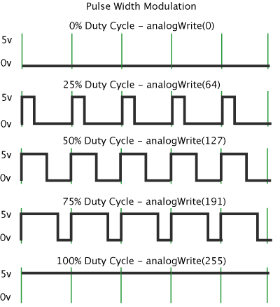
To use PWM in Arduino, you can utilize the analogWrite() function. This function takes two arguments: the pin number and the duty cycle value. The duty cycle value ranges from 0 to 255, where 0 represents no output and 255 represents full output.
Here’s an example code snippet that demonstrates how to use PWM to dim an LED from full brightness to half brightness and back in a loop:
int ledPin = 9; // Pin connected to the LED

void setup() {
  pinMode(ledPin, OUTPUT); // Set the LED pin as an output
}

void loop() {
  for (int brightness = 0; brightness <= 255; brightness++) {
    analogWrite(ledPin, brightness); // Set the LED brightness
    delay(10); // Delay for smooth transition
  }

  for (int brightness = 255; brightness >= 0; brightness--) {
    analogWrite(ledPin, brightness); // Set the LED brightness
    delay(10); // Delay for smooth transition
  }
}
This code gradually increases the LED brightness from 0 to 255 and then decreases it back to 0, creating a fading effect.
For more info, have a look at our tutorial on how to use Pulse-Width Modulation (PWM) to control LEDs, Servos and Motors:
- How use Arduino to control and LED with an Potentiometer
- RGB LED with Arduino Tutorial
- How to Control Servo Motors with Arduino
- How to Drive Servo Motors Using ESP32
- Control 360-degree Servo Motor Using ESP32
- Driving A Linear Actuator Using An Arduino
- How to Control a 360 Degree Servo Motor with Arduino
- How To Control Fan using Arduino – A Complete Guide
- How to Control A Water Pump With Arduino
- How To Control A DC Motor With L293D Driver IC
Key Consideration
PWM is suitable for applications that require precise control of analog devices, such as LED dimming, motor speed control, and audio volume adjustment. Compared to other communication protocols, PWM is relatively simple and efficient in terms of hardware requirements. However, PWM is not suitable for transmitting data or communicating with other devices over long distances.
RS-232, RS-485, and RS-422
RS-232, RS-485, and RS-422 are serial communication protocols commonly used for data transmission between devices. They are widely used in industrial automation, telecommunications, and computer systems.
RS-232
RS-232, also known as EIA-232, is a standard for serial communication between devices. It uses a single-ended communication method, where a voltage level is used to represent binary data. RS-232 supports full-duplex communication, meaning data can be transmitted and received simultaneously. It is commonly used for connecting devices such as modems, printers, and computer terminals.
Here’s a simple code example how to use RS-232 for communication with an Arduino:
#include "SoftwareSerial.h"

SoftwareSerial rs232(2, 3); // RX, TX pins

void setup() {
  Serial.begin(9600);
  rs232.begin(9600);
}

void loop() {
  if (rs232.available()) {
    char data = rs232.read();
    Serial.print("Received: ");
    Serial.println(data);
  }
}
RS-485
RS-485 is a differential serial communication protocol that allows multiple devices to be connected in a network. It uses two wires for communication, one for transmitting and one for receiving. RS-485 supports half-duplex communication, where data can be transmitted in one direction at a time. It is commonly used in industrial control systems and applications that require long-distance communication.
RS-422
RS-422 is similar to RS-485 but supports full-duplex communication. It also uses differential signaling, allowing for better noise immunity and longer cable lengths. RS-422 is commonly used in applications that require high-speed and long-distance communication, such as video surveillance systems and data acquisition.
Key Considerations
RS-232 is suitable for short-distance communication and connecting devices like modems and printers. RS-485, on the other hand, is ideal for long-distance communication and can support multiple devices in a network. RS-422 is similar to RS-485 but supports full-duplex communication and is suitable for high-speed and long-distance applications. Compared to other protocols like UART and SPI, RS-232, RS-485, and RS-422 offer longer communication distances and better noise immunity.
Infrared (IR)
Infrared (IR) communication is a wireless communication protocol that uses infrared light to transmit data between devices. It is commonly used in remote controls, proximity sensors, and communication between devices such as smartphones and TVs.
To use IR communication with Arduino, you will need an IR transmitter and receiver module. The IR transmitter module emits infrared light, while the IR receiver module detects the infrared signals and converts them into electrical signals that can be processed by the Arduino.
The following short code example shows you, how to use the IR protocol for communication with an Arduino:
#include "IRremote.h"

int IR_PIN = 11; // Pin connected to the IR receiver module

IRrecv irrecv(IR_PIN);
decode_results results;

void setup() {
  Serial.begin(9600);
  irrecv.enableIRIn(); // Start the IR receiver
}

void loop() {
  if (irrecv.decode(&results)) {
    unsigned long value = results.value;
    Serial.println(value, HEX); // Print the received IR code in hexadecimal
    irrecv.resume(); // Receive the next IR code
  }
}
This example uses the IRremote library to receive and decode the IR signals. The IR receiver module is connected to pin 11 of the Arduino. When an IR signal is received, the code prints the hexadecimal value of the received IR code to the serial monitor. For more details, see our tutorials on how to use IR communication for remote control:
Key Considerations
Infrared communication is suitable for short-range communication, typically within a few meters. It is a line-of-sight communication, meaning that the transmitter and receiver should have a clear line of sight without any obstacles. IR communication is relatively simple and inexpensive to implement. Compared to other wireless communication protocols like WiFi or Bluetooth, IR communication has a lower data transfer rate. It is especially suited for applications that require simple and low-cost wireless communication, such as remote controls and proximity sensors.
WiFi
WiFi is a widely used communication protocol that allows devices to connect to the internet or communicate with each other wirelessly. It operates on the IEEE 802.11 standard and uses radio waves to transmit data.
To use WiFi with Arduino or other MCUs, you can utilize libraries such as the ESP8266WiFi library for Arduino. Here’s a short code example that demonstrates how to connect to a WiFi network and send a HTTP GET request using an ESP8266 module:
#include "ESP8266WiFi.h"

const char* ssid = "YourWiFiNetwork";
const char* password = "YourWiFiPassword";

void setup() {
  Serial.begin(115200);
  WiFi.begin(ssid, password);

  while (WiFi.status() != WL_CONNECTED) {
    delay(1000);
  }
}

void loop() {
  WiFiClient client;
  if (client.connect("example.com", 80)) {
    client.println("GET /api/data HTTP/1.1");
    client.println("Host: example.com");
    client.println("Connection: close");
    client.println();
  }

  while (client.connected()) {
    if (client.available()) {
      Serial.write(client.read());
    }
  }

  delay(5000);
}
This example connects to a WiFi network specified by the ssid and password variables. It then sends a HTTP GET request to example.com and prints the response to the serial monitor.
For an application of WiFi communication, see our tutorial for an Automatic plant watering system with Arduino IoT Cloud,
Key Considerations
WiFi offers high data transfer rates, making it suitable for applications that require fast and reliable communication. It provides a wide coverage range, allowing devices to connect over long distances. WiFi is commonly used in home automation, IoT devices, and applications that require internet connectivity. Compared to other wireless protocols like Bluetooth, WiFi consumes more power, which may be a consideration for battery-powered devices. Note, that WiFi operates in the 2.4 GHz and 5 GHz frequency bands, which can be crowded in urban areas, leading to potential interference issues.
Ethernet
Ethernet is a widely used communication protocol that allows devices to connect and communicate over a local area network (LAN). It provides a reliable and high-speed connection, making it suitable for various applications.
To use Ethernet with Arduino or other MCUs, you will need an Ethernet shield or module. Here’s a simple code example that uses the Ethernet library to get you started:
#include "Ethernet.h"

byte mac[] = {0xDE, 0xAD, 0xBE, 0xEF, 0xFE, 0xED};
IPAddress ip(192, 168, 1, 100);

EthernetClient client;

void setup() {
  Ethernet.begin(mac, ip);
  delay(1000);

  if (client.connect("www.example.com", 80)) {
    client.println("GET / HTTP/1.1");
    client.println("Host: www.example.com");
    client.println("Connection: close");
    client.println();
  }
}

void loop() {
  if (client.available()) {
    char c = client.read();
    Serial.print(c);
  }
}
This example demonstrates how to establish an Ethernet connection and send a simple HTTP request to a remote server. For more information, see our tutorial on How to use the Ethernet Network Shield 5100 For Arduino UNO.
Key Considerations
Ethernet offers a reliable and high-speed connection, making it suitable for applications that require fast data transfer. Compared to other protocols like WiFi or Bluetooth, Ethernet provides a more stable and secure connection. Ethernet is commonly used in industrial automation, home automation, and IoT applications where a wired connection is preferred over wireless. It supports long cable lengths, allowing devices to be located far apart within a network. However, Ethernet requires physical cabling, which can be more complex to set up compared to wireless protocols.
WebSocket
WebSocket is a communication protocol that provides full-duplex communication channels over a single TCP connection. It enables real-time communication between a client and a server, allowing them to exchange data in both directions simultaneously.
To use WebSocket in Arduino or other MCUs, you can utilize libraries such as ArduinoWebsockets. Here’s a short code example that demonstrates how to establish a WebSocket connection and send data for communication with an Arduino:
#include "ArduinoWebsockets.h"

WebsocketsClient client;

void setup() {
  client.connect("wss://example.com/ws");
}

void loop() {
  client.poll();
  client.send("Hello, server!");
}
Key Considerations
WebSocket provides a persistent connection, allowing real-time communication between a client and a server. It is suitable for applications that require bidirectional communication, such as chat applications, real-time monitoring, and collaborative tools. Compared to other protocols like HTTP, WebSocket reduces the overhead of establishing a new connection for each request. WebSocket is widely supported by modern web browsers and can also be used in embedded systems with appropriate libraries.
Low-Power Wireless Personal Area Network (6LoWPAN)
6LoWPAN (IPv6 over Low-Power Wireless Personal Area Network) is a communication protocol that allows low-power devices to connect to the internet using IPv6. It is specifically designed for wireless sensor networks and IoT applications.
To use 6LoWPAN, you need to have a 6LoWPAN-enabled device or module. Here is a short code example using the Contiki OS and the Contiki-NG stack for communication with an Arduino:
#include "contiki.h"
#include "net/ipv6/uip.h"
#include "net/ipv6/uip-ds6.h"
#include "net/ipv6/simple-udp.h"

PROCESS(example_process, "Example Process");
AUTOSTART_PROCESSES(&example_process);

static struct simple_udp_connection udp_conn;

PROCESS_THREAD(example_process, ev, data)
{
  PROCESS_BEGIN();

  simple_udp_register(&udp_conn, UDP_PORT, NULL, UDP_PORT, receiver);

  while (1) {
    PROCESS_WAIT_EVENT();
  }

  PROCESS_END();
}

void receiver(struct simple_udp_connection *c, const uip_ipaddr_t *sender_addr,
              uint16_t sender_port, const uip_ipaddr_t *receiver_addr,
              uint16_t receiver_port, const uint8_t *data, uint16_t datalen)
{
  // Handle received data
}
This code sets up a simple UDP connection using the Contiki-NG stack. It registers a callback function receiver to handle received data.
Key Considerations
6LoWPAN enables low-power devices to connect to the internet using IPv6, making it suitable for IoT applications. It allows devices to communicate over low-power wireless networks, such as IEEE 802.15.4. To fit within the constrained resources of low-power devices, 6LoWPAN reduces the overhead of IPv6 packets. Compared to other similar protocols like ZigBee, 6LoWPAN provides interoperability with existing IP-based networks. It is especially suited for applications that require low-power consumption, small data payloads, and integration with IP-based infrastructure.
Bluetooth
Bluetooth is a wireless communication protocol commonly used for short-range data transmission between devices. It operates in the 2.4 GHz frequency band and supports various profiles for different applications, such as audio streaming, file transfer, and device control.
To use Bluetooth communication with an Arduino UNO, you will need a Bluetooth module that supports the Serial Port Profile (SPP). One popular module is the HC-05 or HC-06, which can be easily connected to the MCU’s UART pins.
Here is a simple code example using the Arduino SoftwareSerial library to communicate with a Bluetooth module:
#include "SoftwareSerial.h"

SoftwareSerial bluetooth(10, 11); // RX, TX pins

void setup() {
  Serial.begin(9600);
  bluetooth.begin(9600);
}

void loop() {
  if (bluetooth.available()) {
    char data = bluetooth.read();
    Serial.print(data);
  }

  if (Serial.available()) {
    char data = Serial.read();
    bluetooth.print(data);
  }
}
In this example, the module’s RX and TX pins are connected to Arduino pins 10 and 11, respectively. The Arduino receives data from the Bluetooth module and prints it to the serial monitor, and vice versa.
For more details on Bluetooth communication see our tutorials:
- ESP32 And Bluetooth Module- HC-05 – A Complete Tutorial
- Arduino and HC-05 Bluetooth Module Complete Tutorial
- How To Connect ESP32 Bluetooth With A Smartphone
Key Considerations
Bluetooth is suitable for short-range communication (typically up to 10 meters) between devices. It supports low-power consumption, making it ideal for battery-powered applications. In addition, Bluetooth offers a wide range of profiles, allowing for various types of data transmission. Compared to other wireless protocols like WiFi, Bluetooth has lower data transfer rates. Common applications are wireless audio streaming, IoT device control, and wireless data transfer between smartphones and peripherals.
Bluetooth Low Energy (BLE)
Bluetooth Low Energy (BLE) is a wireless communication protocol designed for low-power devices, such as sensors, wearables, and IoT devices. It provides a way for these devices to communicate with each other and with smartphones, tablets, and other Bluetooth-enabled devices.
To use BLE with Arduino or other MCUs, you will need a BLE module or shield that supports the protocol. One popular option is the HM-10 BLE module, which can be easily connected to an Arduino board. Here is a short code example that demonstrates how to use BLE with Arduino:
#include "SoftwareSerial.h"

SoftwareSerial bleSerial(10, 11); // RX, TX pins

void setup() {
  Serial.begin(9600);
  bleSerial.begin(9600);
}

void loop() {
  if (bleSerial.available()) {
    char data = bleSerial.read();
    Serial.print("Received data: ");
    Serial.println(data);
  }

  if (Serial.available()) {
    char data = Serial.read();
    bleSerial.print(data);
  }
}
In this example, we again use the SoftwareSerial library to create a software serial port on pins 10 and 11. The BLE module is connected to these pins. The setup() function initializes the serial ports, and the loop() function continuously checks for incoming data from both the BLE module and the Arduino’s serial port. When data is received from the BLE module, it is printed to the serial monitor. When data is received from the serial monitor, it is sent to the BLE module.
Key Considerations
BLE has a shorter range compared to traditional Bluetooth, but it consumes less power, making it ideal for battery-powered applications. However, BLE has a lower data transfer rate compared to traditional Bluetooth, but it is sufficient for most IoT applications. BLE is especially suited for applications that require low power consumption, short-range communication, and compatibility with smartphones and tablets. Note that BLE is backward compatible with Bluetooth 4.0 and later versions, ensuring compatibility with a wide range of devices.
Near Field Communication (NFC)
Near Field Communication (NFC) is a short-range wireless communication protocol that allows devices to communicate with each other by simply bringing them close together. It operates at a frequency of 13.56 MHz and enables data transfer between devices within a range of a few centimeters.
Here is a simple code example demonstrating how to use NFC with an Arduino:
#include "Wire.h"
#include "Adafruit_PN532.h"

#define SDA_PIN 2
#define SCL_PIN 3

Adafruit_PN532 nfc(SDA_PIN, SCL_PIN);

void setup(void) {
  Serial.begin(115200);
  Serial.println("Hello!");

  nfc.begin();
  uint32_t versiondata = nfc.getFirmwareVersion();
  if (!versiondata) {
    Serial.print("Didn't find PN53x board");
    while (1);
  }
  nfc.SAMConfig();
  Serial.println("Waiting for an NFC card ...");
}

void loop(void) {
  uint8_t success;
  uint8_t uid[] = { 0, 0, 0, 0, 0, 0, 0 };
  uint8_t uidLength;

  success = nfc.readPassiveTargetID(PN532_MIFARE_ISO14443A, uid, &uidLength);

  if (success) {
    Serial.println("Found an NFC card!");
    Serial.print("UID Length: ");
    Serial.print(uidLength, DEC);
    Serial.println(" bytes");
    Serial.print("UID Value: ");
    for (uint8_t i=0; i < uidLength; i++) {
      Serial.print(" 0x");
      Serial.print(uid[i], HEX);
    }
    Serial.println("");
    delay(1000);
  }
}
This code uses the Adafruit PN532 library to read the UID of an NFC card when it is brought close to the NFC module connected to the Arduino. It prints the UID value on the serial monitor.
Key Considerations
NFC is a short-range communication protocol, making it suitable for applications that require close proximity between devices. It operates at a frequency of 13.56 MHz, which is a globally accepted standard for NFC communication. NFC is commonly used for contactless payments, access control systems, and data transfer between smartphones and other devices. Compared to other wireless communication protocols like Bluetooth and WiFi, NFC has a shorter range but offers higher security due to its short-range nature. Note that NFC is not suitable for long-range communication or high-speed data transfer.
Radio Frequency Identification (RFID)
RFID is a wireless communication protocol that allows for the identification and tracking of objects using radio frequency signals. It consists of two main components: RFID tags and RFID readers. The tags contain a unique identifier and can be attached to or embedded in objects, while the readers are used to communicate with the tags and retrieve the stored information.
Here is a simple code example demonstrating how to use RFID with an Arduino:
#include "SPI.h"
#include "MFRC522.h"

#define SS_PIN 10
#define RST_PIN 9

MFRC522 rfid(SS_PIN, RST_PIN);

void setup() {
  Serial.begin(9600);
  SPI.begin();
  rfid.PCD_Init();
}

void loop() {
  if (rfid.PICC_IsNewCardPresent() && rfid.PICC_ReadCardSerial()) {
    Serial.print("Tag UID: ");
    for (byte i = 0; i < rfid.uid.size; i++) {
      Serial.print(rfid.uid.uidByte[i] < 0x10 ? "0" : "");
      Serial.print(rfid.uid.uidByte[i], HEX);
    }
    Serial.println();
    rfid.PICC_HaltA();
    rfid.PCD_StopCrypto1();
  }
}
This code uses the MFRC522 library to interface with the RFID reader module. It initializes the reader, waits for a new card to be present, and then reads and prints the unique identifier (UID) of the detected RFID tag. For more details, have a look at our tutorial on How to use an Arduino and an RC422 RFID Reader.
Key Considerations
RFID is a contactless communication protocol, allowing for easy and convenient identification and tracking of objects. It operates in the radio frequency range, typically around 13.56 MHz. Note that RFID tags can be passive (powered by the reader’s electromagnetic field) or active (with their own power source). Compared to other protocols like NFC, RFID has a longer range but lower data transfer rates. RFID tags are widely used in applications such as access control, inventory management, and asset tracking.
Long Range (LoRa)
LoRa (Long Range) is a low-power, wide-area network (LPWAN) protocol that enables long-range communication between devices. It is designed for applications that require long-range connectivity with low power consumption.
To use LoRa, you need a LoRa module, for instance the RYLR896, or a LoRa-enabled microcontroller. Here’s a simple code example using the LoRa library:
#include "LoRa.h"

void setup() {
  Serial.begin(9600);
  while (!Serial);

  if (!LoRa.begin(915E6)) {
    Serial.println("LoRa initialization failed. Check your connections!");
    while (1);
  }
}

void loop() {
  LoRa.beginPacket();
  LoRa.print("Hello, LoRa!");
  LoRa.endPacket();

  delay(5000);
}
This code initializes the LoRa module and sends a message every 5 seconds.
Key Considerations
LoRa offers exceptional range capabilities, allowing communication over several kilometers in open areas. LoRa devices are designed to operate on low power, making them suitable for battery-powered applications. However, LoRa has a relatively low data rate compared to other wireless protocols. On the other hand, LoRa utilizes spread spectrum modulation techniques, which make it resilient to interference from other wireless devices. We find that LoRa is well-suited for applications such as smart agriculture, asset tracking, smart cities, and industrial monitoring, where long-range communication and low power consumption are crucial.
Radio Frequency (RF)
Radio Frequency (RF) communication is a wireless communication protocol that uses radio waves to transmit and receive data between devices. It is widely used in various applications, including remote control systems, wireless sensors, and IoT devices.
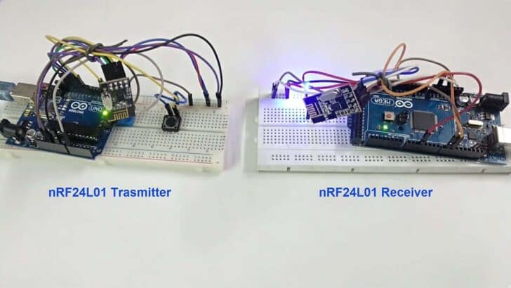
To use RF communication with Arduino or other MCUs, you need an RF module or transceiver that supports the desired frequency range and modulation scheme. One popular RF module is the NRF24L01, which operates in the 2.4GHz ISM band and provides a simple interface for Arduino.
Here’s a short code example demonstrating how to use the NRF24L01 module with Arduino:
#include "SPI.h"
#include "nRF24L01.h"
#include "RF24.h"

RF24 radio(9, 10); // CE, CSN pins

void setup() {
  radio.begin();
  radio.openWritingPipe(0xF0F0F0F0E1LL);
  radio.setPALevel(RF24_PA_HIGH);
}

void loop() {
  char text[] = "Hello, world!";
  radio.write(&text, sizeof(text));
  delay(1000);
}
In this example, the NRF24L01 module is connected to the Arduino using the SPI interface. The radio object is initialized with the appropriate CE and CSN pins. The openWritingPipe() function sets the address for the transmitting module, and the setPALevel() function sets the power level. In the loop() function, the data is sent using the write() function.
For more detail have a look at our tutorial about Wireless Communication with Arduino and nRF24L01.
Key Considerations
RF communication is suitable for applications that require wireless communication over longer distances. It provides good range and penetration through obstacles compared to other wireless protocols like Bluetooth or WiFi. Note that, RF modules are available in different frequency bands, so it is important to choose the appropriate module for your specific application. Also, RF communication requires careful consideration of interference and noise sources to ensure reliable communication. Compared to other wireless protocols, RF communication may have lower data rates and higher power consumption.
ZigBee
ZigBee is a wireless communication protocol designed for low-power, low-data-rate applications. It operates on the IEEE 802.15.4 standard and is commonly used in home automation, industrial control, and sensor networks.
To use ZigBee with Arduino or other MCUs, you will need a ZigBee module that supports the protocol. One popular module is the XBee, which provides a simple way to add ZigBee functionality to your project.
Here is a short code example on how to use ZigBee with Arduino using the XBee module:
#include "SoftwareSerial.h"

SoftwareSerial xbee(2, 3); // RX, TX pins

void setup() {
  Serial.begin(9600);
  xbee.begin(9600);
}

void loop() {
  if (xbee.available()) {
    char data = xbee.read();
    Serial.print(data);
  }

  if (Serial.available()) {
    char data = Serial.read();
    xbee.print(data);
  }
}
In this example, we use the SoftwareSerial library to create a software serial port on pins 2 and 3. The XBee module is connected to these pins for communication. The loop() function reads data from the XBee module and prints it to the serial monitor, and vice versa.
Key Considerations
ZigBee is a low-power, low-data-rate protocol suitable for applications that require long battery life and wireless connectivity. It operates on the 2.4 GHz frequency band, which can be crowded in some environments. ZigBee supports mesh networking, allowing devices to communicate with each other through intermediate nodes, increasing the range and reliability of the network. Compared to other wireless protocols like WiFi and Bluetooth, ZigBee has lower power consumption but slower data transfer rates. ZigBee is especially suited for applications such as home automation, industrial control, and wireless sensor networks where low power consumption and long battery life are important considerations.
Message Queuing Telemetry Transport (MQTT)
MQTT is a lightweight messaging protocol that is designed for efficient communication between devices in IoT applications. It follows a publish-subscribe model, where devices can publish messages to specific topics and other devices can subscribe to those topics to receive the messages.
To use MQTT in Arduino or other MCUs, you need to install the MQTT library. Here’s a short code example that demonstrates how to use MQTT in Arduino:
#include "SPI.h"
#include "WiFi101.h"
#include "MQTT.h"

const char ssid[] = "ssid";
const char pass[] = "pass";

WiFiClient net;
MQTTClient client;

unsigned long lastMillis = 0;

void connect() {
  while (WiFi.status() != WL_CONNECTED) {
    Serial.print(".");
    delay(1000);
  }

  while (!client.connect("arduino", "public", "public")) {
    Serial.print(".");
    delay(1000);
  }

  Serial.println("\nconnected!");
  client.subscribe("/hello");
}

void messageReceived(String &topic, String &payload) {
  Serial.println("incoming: " + topic + " - " + payload);
}

void setup() {
  Serial.begin(115200);
  WiFi.begin(ssid, pass);
  client.begin("public.cloud.shiftr.io", net);
  client.onMessage(messageReceived);
  connect();
}

void loop() {
  client.loop();

  if (!client.connected()) {
    connect();
  }

  if (millis() - lastMillis > 1000) {
    lastMillis = millis();
    client.publish("/hello", "world");
  }
}
Key Considerations
MQTT is a lightweight protocol, making it suitable for resource-constrained devices and low-bandwidth networks. It follows a publish-subscribe model, allowing for efficient and scalable communication between devices. MQTT is widely used in IoT applications for its simplicity and reliability. Compared to Zigbee, MQTT is more focused on messaging and data transfer, while Zigbee provides a complete networking stack. MQTT is well-suited for applications that require real-time data exchange, remote monitoring, and control, and where low power consumption is important. Zigbee, on the other hand, is commonly used in home automation, smart lighting, and industrial control systems.
Constrained Application Protocol (CoAP)
CoAP is a lightweight communication protocol designed for constrained devices and low-power networks. It is specifically designed for Internet of Things (IoT) applications where devices have limited resources such as memory, processing power, and energy.
CoAP operates over UDP and provides a simple request/response model similar to HTTP. It is designed to be efficient and suitable for resource-constrained devices. CoAP supports both unicast and multicast communication, making it suitable for applications where devices need to communicate with each other in a peer-to-peer or group communication fashion.
The following code example demonstrates a simple CoAP server implementation using the CoAPSimple library.
#include "CoAPSimple.h"

CoAPSimple coap;

void setup() {
  coap.begin();
}

void loop() {
  coap.loop();

  if (coap.available()) {
    CoAPRequest request = coap.read();

    if (request.code == CoAP_GET) {
      coap.sendResponse(request, CoAP_CONTENT, "Hello, World!");
    }
  }
}
It sets up a CoAP server and listens for incoming requests. When a GET request is received, it sends a response with the “Hello, World!” message.
Key Considerations
CoAP is designed to be lightweight and efficient, making it suitable for resource-constrained devices. It operates over UDP, which provides low overhead and is suitable for low-power networks. Similar to HTTP, CoAP follows a simple request/response model, making it easy to understand and use. While HTTP is more feature-rich, CoAP is more lightweight and suitable for constrained devices. CoAP is especially suited for IoT applications where devices have limited resources and need to communicate over low-power networks. It is commonly used in smart home automation, industrial monitoring, and environmental sensing applications.
Modbus
Modbus is a widely used communication protocol in the industrial automation field. It allows communication between various devices such as programmable logic controllers (PLCs), sensors, and other devices in a network. Modbus supports both serial and Ethernet communication, making it versatile and adaptable to different setups.
To use Modbus in an Arduino project, you can utilize libraries such as the ModbusMaster library. This library provides functions to easily implement Modbus communication in your code. Here’s a simple code example that demonstrates how to read a holding register using Modbus:
#include "ModbusMaster.h"

ModbusMaster node;

void setup() {
  node.begin(1, Serial);
  Serial.begin(9600);
}

void loop() {
  uint8_t result;
  uint16_t data;

  result = node.readHoldingRegisters(0x0000, 1);

  if (result == node.ku8MBSuccess) {
    data = node.getResponseBuffer(0);
    Serial.print("Data: ");
    Serial.println(data);
  } else {
    Serial.print("Error: ");
    Serial.println(result);
  }

  delay(1000);
}
This code sets up the Modbus communication. It then reads a holding register from a slave device with address 1. If the read is successful, the data is printed to the serial monitor. Otherwise, an error code is displayed.
Key Considerations
Modbus is a widely supported protocol in the industrial automation field. It supports both serial and Ethernet communication, providing flexibility in different setups. Modbus is a simple and efficient protocol, making it suitable for applications that require real-time data exchange. Compared to other protocols like MQTT or CoAP, Modbus is more focused on direct device-to-device communication rather than a centralized message broker architecture. Modbus is commonly used in applications such as SCADA systems, building automation, and process control.
Controller Area Network (CAN)
CAN (Controller Area Network) is a communication protocol commonly used in automotive and industrial applications. It is designed for reliable and efficient communication between microcontrollers and other devices in a network.
To use CAN in Arduino, you need a CAN controller and a CAN transceiver. The MCP2515 CAN controller and MCP2551 CAN transceiver are commonly used with Arduino. Here is a short code example on how to use CAN with Arduino:
#include "SPI.h"
#include "mcp_can.h"

#define CAN_CS_PIN 10

MCP_CAN can(CAN_CS_PIN);

void setup() {
  Serial.begin(9600);

  if (can.begin(MCP_ANY, CAN_500KBPS, MCP_8MHZ) == CAN_OK) {
    Serial.println("CAN bus initialized");
  } else {
    Serial.println("Error initializing CAN bus");
  }
}

void loop() {
  unsigned char data[] = {0x01, 0x02, 0x03, 0x04, 0x05};
  can.sendMsgBuf(0x123, 0, sizeof(data), data);

  delay(1000);
}
Key Considerations
CAN is a robust and reliable communication protocol suitable for applications that require real-time communication and fault tolerance, such as automotive and industrial systems. It supports multi-master communication, allowing multiple devices to send and receive messages on the bus simultaneously. CAN uses differential signaling, which provides noise immunity and allows for long-distance communication. Compared to other protocols like UART, SPI, and I2C, CAN is better suited for applications that require high data rates, long-distance communication, and network scalability. However, CAN is not suitable for low-power applications due to its higher power consumption compared to protocols like Bluetooth Low Energy (BLE) and ZigBee. CAN is widely adopted in the automotive industry and is the standard protocol for in-vehicle communication networks.
Narrowband IoT (NB-IoT)
NB-IoT, also known as Narrowband IoT, is a communication protocol specifically designed for the Internet of Things (IoT) devices. It operates on cellular networks and provides low-power, wide-area connectivity for IoT applications.
To use NB-IoT, you need an NB-IoT module or modem that supports the protocol. The module communicates with the Arduino or other microcontroller using AT commands. Here’s a short example of how to use NB-IoT with Arduino:
#include "SoftwareSerial.h"

SoftwareSerial NBSerial(10, 11); // RX, TX pins for NB-IoT module

void setup() {
  Serial.begin(9600);
  NBSerial.begin(9600);

  // Initialize NB-IoT module
  NBSerial.println("AT+CFUN=1");  // Enable full functionality
  delay(1000);
  NBSerial.println("AT+CGATT=1"); // Attach to the network
  delay(1000);
  NBSerial.println("AT+CEREG=2"); // Enable network registration status
  delay(1000);
}

void loop() {
  if (NBSerial.available()) {
    Serial.write(NBSerial.read());
  }
  if (Serial.available()) {
    NBSerial.write(Serial.read());
  }
}
This example sets up a SoftwareSerial communication between the Arduino and the NB-IoT module. It initializes the module by sending AT commands to enable full functionality, attach to the network, and enable network registration status. The loop function simply forwards data between the Arduino’s serial port and the NB-IoT module.
Key Considerations
NB-IoT provides low-power, wide-area connectivity, making it suitable for battery-powered IoT devices that require long-range communication. It operates on cellular networks, which means it has wider coverage compared to other protocols like Bluetooth or ZigBee. Furthermore, NB-IoT offers excellent penetration through walls and other obstacles, making it suitable for applications in challenging environments. Compared to other cellular technologies like 3G or 4G, NB-IoT has lower data rates but consumes significantly less power, making it ideal for IoT devices that transmit small amounts of data infrequently. NB-IoT is well-suited for applications such as smart metering, asset tracking, environmental monitoring, and agriculture, where long battery life and wide coverage are essential.
GSM/3G/4G
GSM (Global System for Mobile Communications), 3G (Third Generation), and 4G (Fourth Generation) are widely used communication protocols for mobile networks. These protocols enable devices to connect to the internet and communicate with other devices over cellular networks.
To use GSM/3G/4G communication in Arduino or other MCUs, you can utilize a GSM/3G/4G shield or module. These modules typically provide an interface to connect to the MCU and handle the communication with the mobile network.
Here is a short example of how to use GSM/3G/4G communication with an Arduino using the SIM800L GSM module:
#include "SoftwareSerial.h"

SoftwareSerial gsmSerial(10, 11); // RX, TX pins for the GSM module

void setup() {
  Serial.begin(9600);
  gsmSerial.begin(9600);

  // Initialize GSM module
  gsmSerial.println("AT");
  delay(1000);
  gsmSerial.println("AT+CPIN?");
  delay(1000);
  gsmSerial.println("AT+CREG?");
  delay(1000);
}

void loop() {
  if (gsmSerial.available()) {
    Serial.write(gsmSerial.read());
  }
  if (Serial.available()) {
    gsmSerial.write(Serial.read());
  }
}
This example sets up a SoftwareSerial connection between the Arduino and the GSM module. It initializes the module by sending AT commands to check the SIM card status and network registration. The loop function reads data from the GSM module and sends it to the serial monitor, and vice versa.
Key Considerations
GSM/3G/4G communication protocols are widely supported by mobile network providers, making them suitable for applications that require cellular connectivity. These protocols provide higher data transfer rates compared to older generations, with 4G offering faster speeds than 3G. Note that GSM/3G/4G modules require a SIM card to establish a connection with the mobile network. Compared to other wireless protocols like WiFi or Bluetooth, GSM/3G/4G communication allows devices to have a wider range of connectivity, as long as there is cellular coverage. GSM/3G/4G is commonly used in applications such as remote monitoring, asset tracking, and IoT deployments where internet connectivity is required in areas without WiFi coverage.
Conclusion
In this blog post, we have explored various communication protocols that can be used with Arduino and other microcontrollers (MCUs). These protocols enable seamless communication between devices and play a crucial role in the Internet of Things (IoT) ecosystem.
When choosing a communication protocol, it is important to consider factors such as data transfer speed, range, power consumption, compatibility, and security. Each protocol has its own strengths and weaknesses, and the choice depends on the specific requirements of the project.
- UART, SPI, I2C, and 1-Wire are suitable for simple and low-speed communication.
- WiFi and Ethernet provide high-speed and reliable connectivity options.
- Bluetooth and BLE are ideal for short-range wireless communication.
- RFID and NFC are often used for asset tracking and access control systems.
- LoRa and RF are suitable for long-range communication with low power consumption.
- ZigBee is typically used in home automation systems.
- MQTT and CoAP are lightweight protocols for IoT applications.
- WebSocket enables real-time bidirectional communication.
- Modbus is widely used in industrial automation.
- CAN is commonly used in automotive and industrial applications.
- NB-IoT provides low-power wide-area connectivity for IoT devices.
- 6LoWPAN enables IPv6 communication over low-power wireless networks.
- GSM/3G/4G provide cellular connectivity for IoT devices.
I hope this article provided you with a good overview of the many ways to establish communication with Arduino and enables you to select the best method for your project.
Happy coding!
Stefan is a professional software developer and researcher. He has worked in robotics, bioinformatics, image/audio processing and education at Siemens, IBM and Google. He specializes in AI and machine learning and has a keen interest in DIY projects involving Arduino and 3D printing.